Article
1
Design PV Tracking System according to Efficiency
2
in Function of Orientation
3
José Ruelas1,*, Benjamin Pusch 2, Flavio Muños3, Juan Delfin4, Francisco Javier Ochoa Estrella 5
4
Department of Mechanical Engineering, Instituto Tecnológico Superior de Cajeme, Cd.
5
Obregón, Sonora,
Mexico; [email protected] (J.R); [email protected]
6
[email protected] (B.P.); [email protected] (F.M.); [email protected]
7
(J.D.); [email protected] (F.O.);
8
9
* Correspondence: [email protected]; Tel.: +55-644-418-8650
10
11
12
Abstract:
This article proposes a new photovoltaic (PV) solar tracker design based on the13
advantage that installation latitude offers according to efficiency in function of orientation (EFO) of
14
PVs. First, is described a methodology to let incorporate a low-precision, low-cost and
15
high-availability solar tracking mechanism and control system. The design methodology considers
16
the installation location (latitude and azimuth) as a starting point for establishing an adequate
17
angular range of EFO, simultaneity the aspects of available technology and the knowledge accords
18
to developer. Finally, the design technique is experimentally validated by the implementation of a
19
solar tracker at latitude of 28° longitude of 109° and evaluates the efficiency on a specific day.
20
According to result the feasibility of this type of solar tracker for latitudes close to or greater than 30°
21
is highlighted, given that this tracking system costs 30% less than traditional commercial systems as
22
slew drive with its incorporation of lower-resolution azimuth tracking mechanisms. It also increases
23
collection efficiency by 26%, just as continuous or time-based dual-axis solar trackers do, without the
24
more complex controls and mechanisms of these designs.
25
Keywords:
PV
Solar Tracker, Design Methodology, Efficiency Function of Orientation26
27
1. Introduction
28
Photovoltaic (PV) systems frequently incorporate solar tracking systems to maintain their
29
orientation so that the incident solar radiation is normal to the PV surface to increase collection
30
efficiency [1, 2]. Multiple solar tracking systems have been developed, and they can be divided into
31
two types: passive tracking systems, which present low resistance to wind action and feature low
32
installation and maintenance costs, with collection efficiency increases up to 23% [3], and active
33
tracking systems, which can be single-axis and have been reported to increase the collection
34
efficiency by 12-25%, following the solar trajectory along one axis, which can be horizontal, vertical,
35
polar and tilted [4,5]. Active dual-axis solar trackers have been reported to increase the collection
36
efficiency from 30-45%. In general, these dual-axis sun tracking systems can either rotate about the
37
polar and solar declination axes or the azimuth and elevation axes [5]. To achieve this design,
38
ring-rail-type structures, which are designed to support very large PV systems subjected to strong
39
winds [6], can be used mounted on pedestal or central support structures that incorporate linear
40
actuators for polar tracking and a slew drive for azimuth tracking [7,8].
41
In addition, prototypes of other dual-axis solar tracker variants have been presented. For
42
example, [9,10] introduces solar trackers that incorporate robotic actuators, and [11] presents a solar
43
tracker that incorporates complex four-bar mechanisms for solar tracking. To improve the accuracy
44
and performance of dual-axis solar trackers, electronic monitoring systems for obtaining Maximum
45
Power Point Tracking (MPPT) in tandem with solar tracking [12] have been incorporated. Other
46
approaches incorporate different control variants, such as tracking algorithms and techniques with
47
sensors, astronomical equations, diffuse logic, neural networks, time-based tracking systems and
48
Petri networks, according to the recent state-of-the-art review presented in [13,14]. Other studies
49
propose the incorporation of low-cost control devices, such as those presented in [15,16,17], among
50
others.
51
52
In addition to the control methods previously mentioned, which propose strategies and establish
53
performance evaluation mechanisms for single-axis solar tracking, and the definition of three points
54
spaced according to the sun’s trajectory, either daily or annually, as demonstrated in [18,19 and 20],
55
there are also time-based tracking methods, which essentially establish a forward motion of the
56
azimuth tracking at a rate of 15 per hour during a previously established period of the day [21],
57
according to conditions at the installation site. Finally, hybrid solar tracking systems have been
58
proposed, which simultaneously incorporate time tracking and astronomical path equations, along
59
with sensors for improving the robustness of the tracking control systems, as reported in the
60
photovoltaic tracking state-of-the-art review presented recently by Nsengiyumva et al. [13].
61
62
However, according to the previously mentioned studies, no methodology has been presented
63
so far for the development of solar trackers that exploit the advantage offered by the degree of
64
latitude of the installation site for incorporating low-accuracy, low-cost control mechanisms and
65
systems, which also maintain the PV within an adequate range of efficiency as a function of
66
orientation (EFO) [22]. Accordingly, in the present work, a methodology based on the EFO of the
67
installation site is presented, and by incorporating tracking points during the day with a daily tilt
68
adjustment, this method facilitates the development of a low-cost solar tracker by incorporating
69
low-cost, low-resolution control mechanisms and systems based on the available technology
70
71
2. Materials and Methods
72
73
2.1 Methodology description
74
75
The proposed methodology has the goals of developing a strategy for the design of a low-precision,
76
high-efficiency PV tracking system and of facilitating the instrumentation and control required for
77
the prototype. This methodology is based on the Norton design methodology [23]; through relevant
78
modifications, it directs the developer during the design process, incorporating the prototype
79
instrumentation and product control requirements according to the knowledge and devices
80
available to the integrator. After applying this methodology, in addition to obtaining a functional
81
and innovative prototype solar tracker prototype and documentation is obtained by proceeding
82
through the sequential steps presented in Figure 1.
84
Figure 1. EFO solar tracker methodology.
85
86
Step 1.- Input parameters: This step defines the parameters and design rules for a new solar tracker,
87
including latitude of installation established according to a global positioning system (GPS) or maps,
88
available technology and the equipment resources. This information is obtained from
89
manufacturers, suppliers, commercial equipment sellers, and developers.
90
91
Step 2.- EFO for installation latitude: Accord conceptual operational framework is necessary to
92
establish the EFO based on the latitude of PV installation. For example, in [22], the EFO for a location
93
(Bergen, Sweden) corresponds to latitude of 36°. The 100% efficiency for range of tilt angles are
94
between 28° to 48° and orientation angles between -20° to 20°. Next, it is necessary to evaluate
95
whether it is possible to design a new solar tracker with a low-precision PV tracking system with
96
high efficiency, or decline and pursue another method of design, as described in [13].
97
98
Step 3.- Points and trajectory for solar tracking: This section establishes a minimum number of
99
tracking points that can be managed by day according to the EFO range established in the previous
100
step and verified the azimuth and elevation angles range based on the solar trajectory in the
101
installation site throughout the year. According flow diagram of Figure 1 if the solar tracker has a
102
large number of tracking points spaced 15 per hour in a continuous interval, we recommend using a
103
time-based tracking method, as defined in [13].
105
Step 4.- Operation specifications: The results of this step are the paragraphs and/or picture that
106
describe the prototype solar tracker operation, detailing the events and actions occurring over time
107
and including the labels of possible sensors and actuators needed for the instrumentation and
108
control of the new solar tracker.
109
110
Step 5.- Selection and design mechanisms for dual axis tracking: This step consists primarily of the
111
selection of mechanism in accordance with the capacities required for the solar tracker prototype,
112
using comparison matrices that facilitate the selection of devices according to the evaluation
113
criterion, where “H” is assigned to high values, “M” to medium values, and “L” to low values. In
114
addition, calculations are performed on the structures and mechanisms required for develops the
115
prototype, which are supported by computer aided design (CAD) tools and finite element analysis
116
(FEA) and arithmetic calculations.
117
118
Step 6.- Selection of the control technique and device programming: The control technique is
119
selected in accordance with the process to be performed (Grafcet, Petri Nets, Neural Networks,
120
Diffuse Logic), considering the detailed description of the solar tracker prototype operation (Step 4)
121
and the control device selected (FPGA, PLC, microcontroller, industrial PC) based on the
122
previously selected technique. Finally, the program is developed according to the algorithm and
123
control technique previously established in Steps 4 and 5.
124
125
Step 7.- Documentation, implementation and tests: In this step, the documents required for the
126
instrumentation, control and construction of the prototype are recollect. These are typically
127
electrical, pneumatic or hydraulic diagrams, component and prototype construction plans,
128
instrument specifications and program source code. Once the plans and diagrams of the new solar
129
tracker prototype have been developed, the construction and tests are performed to determine if the
130
upgrade fulfils the expectations for the EFO solar tracker prototype. If the results are inadequate, it is
131
necessary to return to Step 5 to consider necessary modifications until the results of the process of
132
obtaining the new solar tracker prototype are satisfied.
133
134
2.2. Case Application
135
Step 1.- Input Parameters: The EFO solar tracker prototype will be installed at a site located at 28°
136
latitude and 109° longitude. In addition, it must meet the following design criteria: low cost, low
137
maintenance, high collection efficiency and improved performance against wind action. The specific
138
parameter values are shown in Table 1.
139
Table 1: Solar tracker design parameters.
140
DESIGN PARAMETERS VALUE Latitude 28 Efficiency 95% - 100% Maximum wind speed 80 km/hr
Capacity 1 kW Cost Lowest Available
Step 2.- EFO for installation latitude: Considering the design rules established in the previous step
142
and the EFO according to the conceptual framework for PV system performance and presented in
143
[22], it is possible to manage tracking errors in the azimuthal axis in a range of ± 30 and tracking
144
errors for the tilt axis in a range of ± 28, maintaining a collection efficiency from 95-100%, as shown
145
in Figure 2.
146
147
Figure 2. Angle range for a PV at 28° latitude with EFO of 95-100%.
148
149
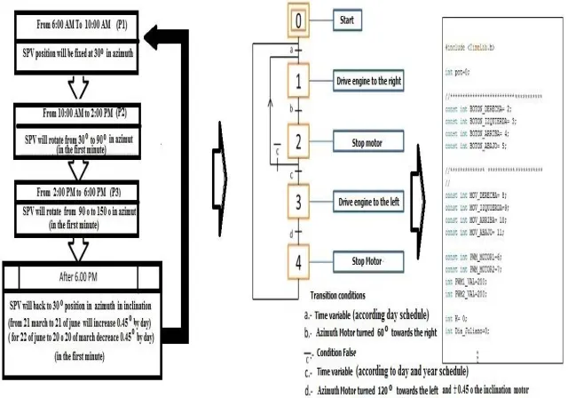
Step 3.- Points and trajectory for solar tracking: Considering an advance of the sun of 15° per hour
150
and accord to azimuth EFO have a range of ± 30° of defacement and hourly solar tracking of
151
following from 6:00 a.m. to 6:00 p.m. the tracking can be divided into 3 spaced points and location
152
according to table 2, with respect to the adjustment of solar height, it is proposed that the follow-up
153
by means of adjust daily according to the declination considering that its greater than 16° and can
154
managed ± 28° according a solar chart for a latitude of 28 ° North and this mechanism is a low cost.
155
156
Table 2. Azimuth Schedule of tracking
157
Position Schedule of tracking
(hours)
Azimuth
(°)
P1 18:01 a 10:00 30
P2 10:01 a 14:00 90
P1 14:01 a 18:00 120
158
Step 4.- Operation specifications: These solar tracking systems follow the sun’s trajectory using a
159
three-point motion for azimuth tracking with a clockwise open-loop control system that operates
160
from 6:00 to 18:00 over a day according to Figure 3 and use a linear actuator for tracking the
161
declination over the year.
163
Figure 3. General Operation descriptions for the solar tracker prototype.
164
165
Step 5.- Selection and design mechanisms for dual axis tracking: The first component to design for
166
the solar tracker is the PV system support structure, which in this case corresponds to a photovoltaic
167
system of 1 kWe composed of four panels of 0.95 m x 1.05 m and 250 W. This supporting structure is
168
designed based on computer-aided design software and finite element analysis CAD/CAE, in which
169
different structures are proposed. An analysis of which structure presents better resistance against
170
wind action is performed, using a wind speed of 120 km/hr, which is chosen based on the maximum
171
wind speed records at the installation location [32]. According to the FEA analysis, the most
172
appropriate structure uses structural steel (PTR-14, PTR-20) and ½” tubing, as shown in Figure 4.
173
174
175
Figure 4. Proposed structure for solar tracker.
176
177
Next, the tracking mechanism is selected based on the decision matrix in Table 3. The most viable
178
option is a DC gear-motor adapted to a transmission due to its low cost and high availability.
179
Table 3. Actuator selection for mechanism tracking.
180
Mechanism Cost Availability Maintenance
Gear-motor transmission
and Lineal actuator L H M
Two Slew Drive M M L
Two Motor indexed H L H
Next, the transmission is designed (Figure 5), which must achieve the proposed resolution without
182
affecting the previously proposed structure. A bevel gear transmission with a total gear ratio of 8:1,
183
composed of a gear-motor coupling dart (1), an upper panel support (2), and bevel gears for
184
transverse coupling (3 and 4), is proposed. The transmission uses A36 steel due to its mechanical
185
resistance.
186
187
Figure 5. Proposed azimuth solar tracker mechanism.
188
189
According to the calculations for a gearmotor and linear actuator (such as the example shown in
190
Figure 6, which is a worm-rack type system with a torque of 80 N/m coupled to a transmission with
191
a step ratio of 12, 0.2 m in diameter), it is possible to withstand the torsion moments caused by wind
192
action over the PV system area.
193
194
Figure 6. Selected actuators.
195
196
Step 6.- Selection control technique and device programming: According to the data previously
197
obtained to fulfil the design requirements, minimizing the amount of movement and taking
198
advantage of the ± 30 windows for maximum efficiency, a time tracking system is proposed. This
199
follows the sun’s trajectory using three points separated by 60 in the azimuth axis (Figure 5), using a
200
microcontroller with limited digital I/O and the capacity to perform basic arithmetic operations and
201
manage the date and time. The tracking begins at point P1, located at 30 above the azimuth axis; the
202
tracker remains at this point until 10:00. Then, one minute later and by activation with an actuator
203
A1, it will move to point P2, located 60 from the previous point, where it will stay until 14:00. Once
204
again, one minute later and by the activation of actuator A1, it will move to point P3 located at 60
205
from the previous point, where it will remain until 18:00. Finally, one minute later, it will return to
206
point P1 by the action of actuator A1 to turn 120 in the opposite direction. It is desirable to
207
incorporate a manual alignment system for the installation of the solar tracker (Figure 7).
209
Figure 7. Proposed solar tracking open loop control.
210
211
A device to perform the proposed control of the A1 activation controller (DC gear-motor) must be
212
selected. A controller with the capacity to manage dates and hours and perform some arithmetic
213
operations is required. We considered a programmable logic controller, a microcontroller and an
214
industrial PC, which are compared in Table 4, which also shows the comparative criteria.
215
216
Table 4, Control device selection matrix.
217
Device Cost Availability Maintenance
PLC M H H
Microcontroller with H bridge L H H
Industrial PC with output interfaces H L L
218
The most viable option for the development of the control system is a system based on a
219
microcontroller combined with an H bridge due to its low cost and its capacity to perform basic
220
arithmetic operations and facilitate the incorporation of a manual alignment system for the
221
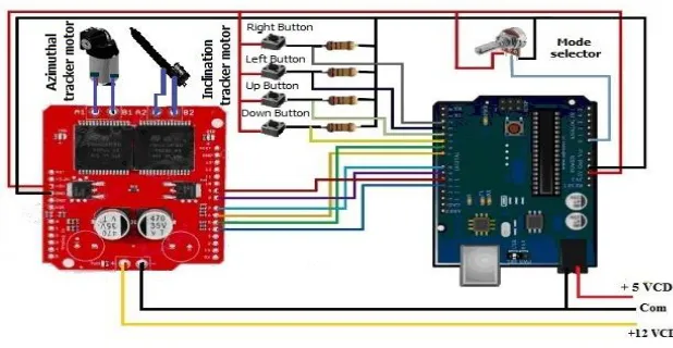
installation of the solar tracker, according to the schematic shown in Figure 8.
222
223
Figure 8. Controller connections schematic.
In table 5 before developing the controller, a control technique must be selected according to the
226
characteristics and the operation of the solar tracker prototype mentioned in the previous step.
227
228
Table 5. Selection of the control algorithm technique.
229
Technique to elaborate the control mechanism
Hardware
requirements Complexity Knowledge
Grafset M M H
Petri nets H H L
Flow Diagrams L L M
230
The Grafcet technique is selected, mainly because the authors have a large amount of knowledge in
231
applying this technique. Figure 9 illustrates the Grafcet technique used to develop the program for
232
the low-cost microcontroller selected in the previous step.
233
234
Figure 9. Controller programming process.
235
236
Step 7.- Documentation, implementation and tests
237
a) Documentation
238
To proceed with the development of the solar tracker prototype, it is necessary to generate
239
documentation as; the specification of the actuators (Figure 6), the microcontroller electronic circuit
240
diagram (Figure 8), the source code of the solar tracker control program (Figure 9), and the structural
241
plans of the tracking system (Figure 10).
244
Figure 10. Plans for the proposed structure.
245
246
b) Implementation
247
The final implementation of the EFO solar tracker prototype is shown in Figure 11, which shows the
248
location of the control system and the A1, A2 actuators. The actuator A1 and mechanism according
249
to [24] have a 30% low cost than a slew drive uses for solar tracker [25].
250
251
Figure 11. Solar tracker prototype and components.
252
253
c) Test
254
The solar tracker prototype’s resistance to wind was tested for a specific place (28° latitude and 109°
255
longitude) during 2017. During this period, the tracker remained operational and withstood
256
maximum wind gusts of 84 km/h according to data obtained from the weather station installed at the
257
same location. The solar tracker efficiency was maintained within a range of 26-30%, as shown by the
258
results of the experimental test performed on May 4, 2018. The details regarding instrumentation
259
and recording of the PV efficiency measurements are provided in the result section.
3. Results
261
The efficiency measurement was performed by recording the power delivered by the fixed PV
262
module and by another tracking PV module model ERDM 225, The measuring voltage and current
263
was performed using the electric circuit shown in the schematic of Figure 12.
264
265
266
Figure 12. Schematic of the PV power measurement.
267
268
The comparative results for the PV panel placed in a solar tracker prototype located at Cd.
269
Obregon, Mexico (28° latitude and 109° longitude) on 04 May 2018 are shown in Figure 13. Data
270
were captured every 30 min for the average daily production achieved by the panels performing the
271
tracking. The tracking solar panel collected 26-35% more energy than the energy collected by the
272
fixed photovoltaic panel.
273
274
0 20 40 60 80 100 120 140
06:00 07:00 08:00 09:00 10:00 11:00 12:00 13:00 14:00 15:00 16:00 17:00 18:00
Hour
P
o
w
e
r
(W
)
0 100 200 300 400 500 600
Hour
R
a
d
ia
ti
o
n
(
W
/m
^
2
)
POTENCIA FIXED (W)
POTENCIA TRACKER (W)
RADIACION (W/m^2)
275
Figure 13. Energy produced by the photovoltaic panels (fixed and tracking).
276
4. Conclusions
277
The photovoltaic solar tracker design is based in a methodology that is recommended to use in a
278
latitudes in close proximity to 30 because the increase in collection efficiency of the solar trackers as
279
similar to others solar trackers that incorporate better control tracking technology and more precise
280
mechanisms but with more costly and complex and evaluating the possibility of adjusting the EFO
281
to incorporate this type of tracker at other latitudes by means the proposes methodology.
The proposed methodology let to develops a low cost photovoltaic solar trackers and the case of
284
latitudes close to or greater than 30° is highlighted, given that this tracking system (azimuth
285
mechanism) costs 30% less as than traditional commercial systems by means incorporation of
286
lower-resolution azimuth tracking mechanisms. It also increases collection efficiency by 26%, just as
287
continuous or time-based dual-axis solar trackers do.
288
289
Acknowledgements: The authors extend their gratitude to CONACYT and TECNM for their
290
support in Project 06-PD.
291
292
Author Contributions: All the authors have designed the experiment and worked in the
293
development of the prototype throughout the project. Jose Ruelas and Roberto Favela created and
294
designed the experiments. Jose Ruelas and Flavio Muños analyzed the data; Jose Ruelas and Javier
295
Ochoa wrote the article and Jose Ruelas and Juan Delfin analyze the documents.
296
297
Conflicts of Interest: The authors declare no conflict of interest.
298
References
299
1. M.H.M. Sidek a, N. Azis a, *, W.Z.W. Hasan a, M.Z.A. Ab Kadir a, S. Shafie a, b, M.A.M. Radzi
300
a, Automated positioning dual-axis solar tracking system with precision elevation and azimuth
301
angle control, Energy, 2017, 124, 160-170.
302
2. S.A. Sharaf Eldin a, M.S. Abd-Elhady b, *, H.A. Kandil, Feasibility of solar tracking systems for
303
PV panels in hot and cold regions, Renewable Energy , 2016, 85, 228-233.
304
3. Clifford M, Eastwood D. Design of a novel passive solar tracker. Sol Energy 004;77:269–80.S
305
4. Chong Kok-Keong, et al. Integration of an on-axis general sun-tracking formula in the
306
algorithm of an open-loop sun-tracking system. Sensors 2009,9, 7849–7865.
307
5. Rajesh Singh, Suresh Kumar, Anita Gehlot, Rupendra Pachauri, An imperative role of sun
308
trackers in photovoltaic technology: A review, Renewable and Sustainable Energy Reviews
309
2018, 82, 3263–3278.
310
6. P. Visconti, P. Costantini, C. Orlando, A. Lay-Ekuakille, G. Cavalera, Software solution
311
implemented on hardware system to manage and drive multiple bi-axial solar trackers by PC in
312
photovoltaic solar plants, Measurement , 2015, 76, 80–92
313
7. Saban Yilmaz a,n, HasanRizaOzcalik b, OsmanDogmus a, FurkanDincer c, OguzhanAkgol d,
314
Muharrem Karaaslan, Design of two axes sun tracking controller with analytically solar
315
radiation calculations, Renewable and Sustainable Energy Reviews 2015, 43, 997–1005
316
8. Sebastijan Seme, Gregor Srp_ci, Domen Kav_sek, Stane Bo_zi_cnik, Tomislav Letnik, Zdravko
317
Praunseis, Bojan _Stumberger, Miralem Had_ziselimovi, Dual-axis photovoltaic tracking
318
system e Design and experimental investigation, Energy 2017, 139, 1267-1274.
319
9. Alessandro Cammarata, Optimized design of a large-workspace 2-DOF parallel robot for solar
320
tracking systems, Mechanism and Machine Theory 2015, 83, 175–186.
321
10. Flores D, Palomino S, Lozada N, Luviano A, Chairez I. Mechatronic design and implementation
322
of a two axes sun tracking photovoltaic system driven by a robotic sensor. Mechatronics
323
2017,47, 148–159.
324
11. J. González, C. Palacios, J. Flores, Analytical synthesis for four–bar mechanisms used in a
325
pseudo–equatorial solar tracker, ingeniería e investigación 2013, 33, 55-60.
326
12. Tobón, A.; Peláez-Restrepo, J.; Villegas-Ceballos, J.P.; Serna-Garcés, S.I.; Herrera, J.; Ibeas, A. Maximum
327
power point tracking of photovoltaic panels by using improved pattern search methods. Energies 2017, 10,
328
1316.
13. Walter Nsengiyumv, Shi Guo Chen, Lihua Hu, Xueyong Chen, Recent advancements and
331
challenges in Solar Tracking Systems (STS): A Review, Renewable and Sustainable Energy
332
Reviews 2018, 81, 250–279.
333
14. Masoume Shabani, Javad Mahmoudimehr, Techno-economic role of PV tracking technology in
334
a hybrid PV hydro electric standalone power system, Applied Energy 2018, 212, 84–108.
335
15. Carlos Morón, Daniel Ferrández, Pablo Saiz, Gabriela Vega, Jorge Pablo Díaz, New Prototype of
336
Photovoltaic Solar Tracker Based on Arduino, Energies 2017, 10, 1298.
337
16. Bouziane Khadidjaa, Korichi Drisa, Azoui Boubekerb, Settou Noureddine, Optimisation of a
338
Solar Tracker System for Photovoltaic Power Plants in Saharian region, Example of Ouargla,
339
Energy Procedia 2014, 50, 610 – 618.
340
17. Jerin KuriakoseTharamuttamaAndrew KeongNg, Design and Development of an Automatic
341
Solar Tracker, December 2017,143, 629-634.
342
18. Hao Zhong, Guihua Li, Runsheng Tang, Wenli Dong, Optical performance of inclined
343
southenorth axis three-positions tracked solar panels, Energy 201, 136, 1171-1179.
344
19. Bin Ai, Hui Shen, Qun Ban b, Binghou Ji, Xianbo Liao, Calculation of the hourly and daily
345
radiation incident on three step tracking planes, Energy Conversion and Management 2003,
346
44, 1999–2011.
347
20. Vijayan Sumathi, R. Jayapragash, Abhinav Bakshi, Praveen Kumar Akella, Solar tracking
348
methods to maximize PV system output – A review of the methods adopted in recent decade,
349
Renewable and Sustainable Energy Reviews 2017,74, 130–138.
350
21. Ming-Cheng Ho et al. / Design and Construction of Prototype Mobile Sun-Tracking System for
351
Concentrator Photovoltaic System, Energy Procedia 2017, 142, 736–742.
352
22. J. Haller, S. Voswinckel, V. Wesselak, The effect of quantum efficiencies on the optimum
353
orientation of photovoltaic modules – A comparison between crystalline and thin film modules,
354
Solar Energy 2013, 88, 97–103.
355
23. Norton R. Diseño de Maquinaria: Síntesis y Análisis de Máquinas y Mecanismos, 4ta ed.
356
México, McGraw-Hill. 2009.
357
24. Industrial Machining, https://www.maquinadoseversteel.com/ (accessed on 5 May 2018).
358
25. Slewing Drive and Ring Manufactures, http://www.slew-ring.com (accessed on 5 May 2018).