A REVIEW: SIMULTANEOUS LOCALIZATION AND MAPPING IN APPLICATION TO AUTONOMOUS ROBOT
Agunbiade OY and Zuva T Vaal University of Technology,
Andries Potgieter Blvd Vanderbijlpark 1900, South Africa. email:[email protected]/[email protected]
Abstracts
The important characteristic that could assist in autonomous navigation is the ability of a mobile robot to concurrently construct a map for an unknown environment and localize itself within the same environment. This computational problem is known as Simultaneous Localization and Mapping (SLAM). In literature, researchers have studied this approach extensively and have proposed a lot of improvement towards it. More so, we are experiencing a steady transition of this technology to industries. However, there are still setbacks limiting the full acceptance of this technology even though the research had been conducted over the last 30 years. Thus, to determine the problems facing SLAM, this paper conducted a review on various foundation and recent SLAM algorithms. Challenges and open issues alongside the research direction for this area were discussed. However, towards addressing the problem discussed, a novel SLAM technique will be proposed.
Keyword: Autonomous robot, illumination variance, kidnap robot, dynamic environment, navigation, simultaneous localization and mapping
1 INTRODUCTION
Simultaneous Localization and mapping (SLAM) is an important problem that has been broadly researched in robotics. Its contribution towards autonomous robot navigation has attracted researchers towards focusing on this area (Fuentes-Pacheco et al., 2015, Zunino and Christensen, 2001). In the past, various techniques for addressing simultaneous localization and mapping has been proposed with remarkable achievements. Research had been conducted based on several types of sensors because of their advantage to one another; also sensor selection can be as a result of the type of technique they are proposing to solve the SLAM problem (Steckel and Peremans, 2013). In (Eliazar and Parr, 2003), they proposed to address the SLAM problem in an environment without pre-determined landmarks using laser sensors. The Particle filter algorithm was deployed on their system and had produced a highly detailed map for an office environment. Laser sensors apart from being expensive could produce a wrong measurement when encountering shiny or black objects that do not reflect light and this could affect robot localization in an environment (Agunbiade et al., 2014). In (Zunino and Christensen, 2001) they proposed the use of the EKF filter algorithm to process the information obtained by the sonar sensors attached to the robot. The sonar sensor was proposed because of its low cost and low computational complexity for retrieving information from the environment. In the work of (Steckel and Peremans, 2013), they condemn the use of sonar sensors because of its inability to provide fine-grained information from sound. Instead, they proposed bio-sonar.This was employed due to high intelligent interaction capability towards a complex environment and its ability to extract more information from the echoes than sonar. BatSLAM algorithm was proposed to analyse the information acquired by the bio-sonar, but from their experiment, the system limitation occurs if it encounters a larger complex environment because
echoes arriving from different directions are delayed. Trying to analyse them produced an invalid cue which makes the system fail to navigate correctly (Hiryu et al., 2010). In the work of (Irie et al., 2012), they proposed a vision-based SLAM, because the camera was able to acquire more information from the environment than other sensors which could improve robot navigation (Zehang et al., 2006). Thus, being aware of the issues of environmental noise with vision-based system, they tend to address the issue of shadow. They proposed the use of two-dimensional occupancy grid maps produced from 3-D point clouds obtained by a stereo camera, they also introduced an extracted salient line segments from the ground into the grid map. On the grid map, robot pose estimation was attained by employing particle filters. In this technique, the grid maps were not affected by shadow and lighting conditions, but under severe illumination condition, it is impossible to extract the salient line segment which resulted to a failed SLAM technique. However, the issue of illumination variance support while some researchers still prefer the use of active sensors to acquire data from the environment (Thamrin et al., 2012). Furthermore, for reliable and accurate measurement of the environment, the work of (Castellanos et al., 2001) propose the use of multiple sensors to attain an impressive result so that one sensor can take advantage over the weakness of another. But the major limitation is high computational complexity when combining too much data from multiple sensors. Hence, irrespective of the sensor employed, they all have their limitations. However, sensors are not the only contributor to SLAM failure, algorithm employed to address the SLAM problem also have their limitations and they will be discussed in the next section. In this paper, Section 2 and 3 discuss the foundation and recent SLAM algorithm while section 4 discusses the challenges, open issues and research direction.
2 FOUNDATIONAL SIMULTANEOUS LOCALIZATION AND MAPPING
ALGORITHMS
In an attempt to develop an efficient and effective technique that can address SLAM problem, sensors play an important role of acquiring data from the environment (Zehang et al., 2006) but localization and mapping techniques are not limited to this operation. There are several procedure that still need to be implemented, for instance, the analysis of the data captured assist in mapping building and localization, this can be attained by using SLAM algorithm (Chen, 2013). In the literature, several foundation SLAM algorithms has been proposed with outstanding result but they are all confronted with various challenges and issues (Hadji et al., 2014). In this section, some of these algorithms will be discussed together with their limitation and advantages.
2.1 Extended Kalman Filter
In the review involving Extended Kalman Filter (EKF), it is important to mention the Kalman filter because it is the foundation for EKF and some algorithms like Extended Information Filter (EIF), non-linear least-square etc. (Hadji et al., 2014). Researchers over the years have employed Kalman filter as an algorithm to estimate dynamic linear systems with Gaussian noise (Chen, 2013). Kalman filter represent a
state vector
t given in equation (1).
t N
t S , l1,l2...,l
It is formulated by estimating the landmark (l)where N represents numbers of map landmark, the current pose
St , as well as a covariance matrix
t
which signifies the covariance between the statevariance also a measure of confidence. However, the issue of non-linearity in the robot model is the limitation of the Kalman filter algorithm and trying to address this issue led to Extended Kalman filter (Hadji et al., 2014).
Extended Kalman Filter (EKF) is an upgraded version of a Kalman filter that can address non-linear model (Chen, 2013). The linearization of non-linear model can be solved by many methods but in EKF, a technique called first order Taylor expansion is employed to address this issue. At each time (t), it linearize the measurement and motion model using the current state to estimate for a new update (Chen, 2013). The filter procedure is attained with two steps given in section 2.1.1 and 2.1.2.
2.1.1 The Time Update stage
At this stage, the filter computes the covariance matrix
t and the predicated state
t
at time (t).Expressions is given in equations (2) and (3).
t t
t f 1,u
(2)
1 t T u T t tt A A G G (3)
where At signifies the Jacobian of the motion model f as related to the robot pose St that is
evaluated at
t, ut represent the robot control, u signifies the covariance matrix related to this stage and G represent a projection matrix.2.1.2 The measurement update stage
This stage plays a significant role to address the problem of data association
c and generate the newupdated measurement for
t and
tusing the current state of the previous stage. They are computed byestimating first, the Kalman gains as given in equations (4)-(6).
1
t tT t
t tT Zt C C C
K (4)
c h z
Kt t t
t
t
,
(5)
t
t I KtCt (6)
Where I represent identity matrix, Kt represents the Kalman gain, Ct represent the Jacobean of
the measurement model h in relation to every detected land marks estimated at
robot, zsignifiesthecovariance matrix as related to this stage and ztrepresent the sensor measurement
(Chen, 2013).
The above listed two steps are unique to EKF and can be use to instantiate the online SLAM given a condition of Gaussian model. The EKF is a popular algorithm because of the ability to overcome the problem of Kalman filter, but the computational cost of the algorithm is high (Dissanayake et al., 2011).
2.2 Sparse Extended Information Filter
Considering the limitation of high computational cost of EKF, this shifted researchers attention to a more advance filter known as Extended Information Filter (EIF). In EIF high computational cost was reduced by avoiding the computation of the Gaussian posterior in terms of the mean
and the covariance matrix
instead, the filter employs the information form of the posterior, which uses the information matrixH and information vector b(Chen, 2013). The parameterization is given below in equation (7) and (8)
1
H (7)
H
b
T (8) The EIF operational function is related to EKF, but the time update and measurement update stage are parallel to that of EKF, the equation 5 and 6 of the Extended Kalman Filter are transformed in EIF using the generated parametric value of information vector and information matrix (Chen, 2013). The parametric substitution for these stages are given in equations (9) - (12).2.2.1 The Time Update stage
1 11( ) ]
[
u T
T t t
t
t I A H I A S S
H (9)
t T t t t
t H f u H
b b
( ( 1, ) )
1 1
1
(10)where Irepresent identity matrix, At signifies the Jacobean of the motion model f estimated at
t
, the projected matrix is signified as S. At this stage, the updated time estimated is managed to its bestbecause of the mean
t recovery and the inversion of a denseHt. However, constant time updates canbe attained if Hthas a sparse characteristic and
tis available for all landmarks and robot poses, this is attained at the next stage (Chen, 2013).2.2.2 The measurement updated stage
T t z t t
t H C C
H 1
(11)
T t z T t T t t t t
t b z z C C
b 1
where zt zt
represent the difference between updated and current sensor measurement, Ct
signifies the Jacobean of the measurement model estimated at
t. At this stage, it requires only constanttime summation taking into consideration that C is sparse with non-zero values for the observe landmarks and pose in the measurement (Chen, 2013). Given this condition for every step of a matrix,
non-zero values will only be associated to
t
H . EIF is regarded as an approximation approach with an improved processing speed better than EKF because of low computational complexity. However, as a result of approximation, the issue of inconsistency has not been resolved (Dissanayake et al., 2011).
2.3 Rao-Blackwellized Particle Filter
In the work of Murphy, Rao-Blackwellized particle filter is implemented to estimate the joint posterior
p S1:t,mZ1:t,U1:t1
of a map
m and the robot trajectory
S1:t S1,...,St
. The estimation iscarried out given the odometry measurement
U1:t1U1,...,Ut1
and the observation measurement
Z1:t Z1,...,Zt
of the robot. Using the information provided above, the Rao-Blackweilized particlefilter used the factorization given in equation (13) to represent SLAM (Wurm et al., 2003).
S1:t,mZ1:t,U1:t1
p
mS1:t,Z1:t
.pS1:t Z1:t,U1:t1
p (13)
In the factorization procedure, the trajectory of the robot is first estimated, then the map given that same trajectory computed. This is mandatory because the map creation rely on the estimated robot pose [22]. The Rao-Blackwelized particle filter offers efficient computational cost with improved processing speed. Its representation in equation (13) can be formulated efficiently to address SLAM since the posterior of
the map p
mS1:t,Z1:t
will be estimated by employing the technique of mapping with known poses given that S1:tand Z1:t are known (Wurm et al., 2003). In computing the posterior p
S1:t Z1:t,U1:t1
forpotential trajectories, particle filter may be employed. Since every particle corresponds to a potential robot trajectory and individual maps are connected with each sample. Therefore, maps will be created using the observation and corresponding particle relating to the trajectory. This procedure allows the robot to learn models of their environment and estimate successfully their trajectory (Wurm et al., 2003). Thus, the particle filters effectiveness and complexity rely heavily on the number of particles. The increase in the number of particles might improve its effectiveness, but at a price of high computational cost. Otherwise, the effectiveness can be minimized with low computational cost. However, estimating an optimal number of particle required is often difficult to attain (Montemerlo and Thrun, 2003).
3 RECENT PROPOSED SLAM ALGORITHMS
The simultaneous localization and mapping is an important problem to consider as far as autonomous guidance is concerned (Fuentes-Pacheco et al., 2015). Thus, successful navigation of a robot given in an unknown environment require continuous updating of map while simultaneously estimating its position in its environment. In literature, researchers have presented recent technique to overcome the challenges of the foundational SLAM algorithm (Khairuddin et al., 2015). This section will discuss some of these techniques, their challenges and issue they encountered during their implementation. Furthermore, this section will disclose recent issue because reviews are only conducted on recent techniques only.
In the work of (Agha-mohammadi et al., 2015), they propose to replan at every time
k whenthere is a probability distribution update on the state of the autonomous robot, this technique is referred to as: Simultaneous localization and Planning. The algorithm employed to carry out this task is known as Partially Observable Markov Decision Process (POMDP). This algorithm was proposed because of its ability to cope with uncertainties and changes. The idea employed in motion planning under uncertainty is to identify a policy
k at each time
k that generate control state
Uk using the available information of the robot. Thus, there are other important terms that needs to be defined to achieve thisgoals. Given a robot in an unknown environment whose state is represented by xk at time step
k , themotion noise and control state at time
k is represented by Wk and Ukrespectively. The state evolutionmodel can now be formulated using equation (14)
x k k
k f x U W
x 1 , , (14) However, in any partial observable system, the sensor vector measurement at very time k represented as
k
Z plays an important role of providing observation measurement. The expression for Zkis given in equation (15).
k k
k h x V
Z , (15) where Vk denotes sensing noise.
On this note, the data available for deriving decision at each time k is the history of controls and observation as expressed in equation (16), the conditional probability distribution for the overall possible robot state is given in equation (17)
0: , 0: 1
0, 1,..., , 0,..., 1
k Z K U k Z Z Zk U Uk (16)
k k
k p x H
The bkgenerated in equation (17) is also referred to as information state or belief that compressed the
data kand can be recursively computed using the last state and current observation as expressed in equation (18)
k k X k k k k k
k pZ x p x x U b dx
b 1 1 1 1 , (18)
where represent the normalization constant and the Uk can be generated based on the
information state using a policy
k as expressed in equation (19)
k kk b
U
(19)the
k represent the solution of a POMDP over a continuous observation space with a limitation that is intractable. In addressing this issue, Feedback based Information Road Map (FIRM) was proposed to minimize the intractable problem to a tractable POMDP by generating a representative graph in the information state space.Given a FIRM graph with controller, policy
gcan be extracted by mapping graph nodes
v to the edge
m as expressed in equation (20)m v
g
:
(20)Thus, the set of all graph planar
g generated in an information state space allows POMDP to be tractable on the FIRM graph as expressed in equation (21)
o n
n g n g g
B B
C g
argmin , (21) where visited n-th node is represented by Bn.,
n
g n g
B B
C ,
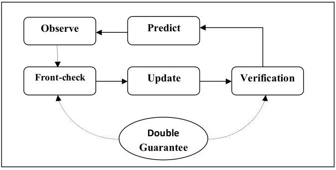
signifies the cost function. Experimental performance attained is impressive, but the limitation is inability to cope with dynamic environment. In their future work, they want to propose a frame work that can learn and model changes using prior knowledge of object motion.Figure 1: The overall workflow of the DGKD model (Tian and Ma, 2016)
However, DGKD limitations is the inability to cope with relatively large-scale environment and to increase its adaptability in large scale environment, the probability of features position and robot pose was combined to DGKD to form a new technique known as Probabilistic double guarantee kidnapping detection (PDGKD). In PDGKD, giving a robot state
Xr
expressed in equation (22) and the state of feature
Xm
given in equation (23).
Tr r r
r x y
X , ,
(22) where
xr,yr
signifies position while rdenote frame orientation of the robot,
T
Tm T m
m X X
X 1, 2,... , (23) whileXmi signifies the position of the feature
i in the global coordinate as expressed in equation (24). r r i L i L r r r r mi y x y x X
cos sin sin cos (24) i L i L yx, denotes the position of feature i referred to the local coordinates frame attached on the robot.
Hence, the derived state vector combines both features state
Xm
and robot state
Xr
has expressed inequation (25) to address the DGKD SLAM problem.
T
Tm T r X
X
X , (25)
Observe Predict
Front-check Update Verification
Double
In PDGKD, the operations are not only limited to the above mentioned process, there are other procedures like prediction and updating operation similar to that of DGKD, but the difference is the metric employed in their systems. Experimental comparison between the two technique shows that PDGKD achieves better result than DGKD. However, the limitation of the system arose when kidnap robot happens over a long period of time.
In the technique of (Tan et al., 2015), simultaneous localization and mapping without linearization was proposed to overcome the issue of linearization and inconsistency caused by approximation limiting the effectiveness of EKF-SLAM. This was achieved by combining both linear time varying Kalman filter and contraction tools on navigation problem with virtual measurements. Given a robot with LTV Kalman filter SLAM using a virtual measurement in local coordinates, the EKF is the basis of LTVK and it would start with available non-linear measurement given in equation (26)
b a x x arctan
and/or r xa2 xb2 (26)where
represent the measure azimuth angle of the robot,
xa,xb
represent location of landmark andr
represent range measurement between robot and landmark. Afterwards the estimated Jacobian is employed to linearize this measurement to a locally stable observer. Expression of the relation in Cartesian coordinate is given in equation (27).hx0 and/or h*xr (27) But in 2D and 3D scenarios, expression is given in equations (28) and (29)
cos,sin
h and/or *
sin
,cos
h (28)
cos 0 cos sin sin sin sin cosh and /or h*
cos
sin
,cos
cos
,sin
(29)Given a linearize equation in local coordinate, the azimuth model representation for actual location of a landmark in 2D and 3D is expressed in equation (30) and (31)
T
Tr r x
x , sin
, cos
x 1 2 (30)
T
Tr r
r x
x , cos
sin
, cos
cos
, sin
x 1 2 (31)
where h/h* represent state independent measurement vector,
represent the actual location of a landmark.In LTVK, measurement and observation between and rare ignored while feedback on tangential and
t v Hy x (32) where y represent observation/measurement vector which contains virtual/actual measurement,
Hrepresent observation model matrix that include state-independent measurement vectors and v
trepresent zero-mean white noise. If further exploited can be employed to attain a globally stable observer design with no set back error caused by linearization operation. However, this achievement is at a price of high computational cost and in their future work, they plan to reduce the computational workload by using the technique suggested by (Mu, 2013). The technique proposed the use of landmark with more provided information for feature selection to assist in reducing computational workload.
In the work of (Jia et al., 2016) vision-based technique using a monocular camera was proposed to initiate SLAM. The algorithm employed in their technique is known as Parallel, Tracking and Mapping (PTAM). In PTAM, procedures are split into two level task operations in parallel. In the tracking level, monocular camera fixed on mobile robot is used to capture images from the environment. Ground feature-based pose estimation algorithm was proposed to detect ground features. But to achieve a more accurate robot pose, a weighted projection error-based energy function expressed in (33) was used to achieve this task.
xmin
x wrp rp (33)
where w represent the tukey biweight function for the homography-based projection error
rp .Given the accurate robot localization attained by the expression in (33), matched features triangulated was used to generate an initial map. Afterwards is the second level task known as mapping thread, during this task, the initialized map is queried for incorporating new key features and these is achieved by employing the use of epipolar searching procedure. The new matched features are selected for acceptance by searching for candidate region around the epipolar with minimal differences of Zero-Mean Summed Squared Differences (ZMSSD), while candidate region with higher differences in ZMSSD compared to the threshold will be rejected for re-mapping. Expression is given in equation (34)
reject r
accept r
u s
i j
i j i j
(34)
where
ij i j i
j H v u
r
,i
H represent the homography estimated by RANSAC algorithm, vij signifies the reference feature of
i j
u , rj represent the projection error and
i represent the threshold.The work presented in the study of (Agarwal and Burgard, 2015) is a graph based simultaneous localization and mapping. The concept of graph-based SLAM relies on representing the nodes present in the graph by each pose attained by the robot. In real world scenario, these nodes can be used to signify features extracted from images captured by camera sensors or laser point cloud. Nodes can also be employed to signify physical landmark of object like trees, cars etc. Edges present in the graph is signified by a factor connecting two nodes. These factors represent the bearing measurement of features. Given a robot navigating in an unknown environment using graph-based SLAM, the first problem to address is creating a graph. This can be attained by identifying the nodes and the factors connecting these nodes based on the data generated from the sensors, this computation is known as front-end. The second problem to address is the nodes configuration that provides best explanation for the factors. These steps assist to compute a maximum likelihood map and these computations is known as back end. Thus, the back ends aim to find configuration of nodes that minimize error created by the factors from the front-end
operation. If x
x1,...,xn
Trepresent a state vector and xi signifies pose of node i which can alsorepresent a robot or landmark position. The error function
eij
x
description for a single factor betweeniand j represent the different between Zij and Z
xi,xj
. Expression is given in equation (35).
i j
ij ij x Z x x Ze
, (35)
where Z
xi,xj
signifies the expected measurement given in the current state, Zij represent the
observed measurement, iand jrepresent the graph nodes. The re-projection error of the observed landmark must be minimized for accuracy purpose. Thus, the minimization error can be expressed in equation (36)
ij ij
ij T ij x
x e x
e 1
min arg
x (36)
where
1ij represent information matrix related to the factors that exist between two pose xi
and xj,
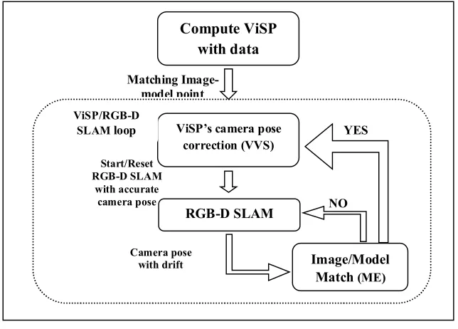
ijsignifies the covariance matrix and x represent the optimal configuration of nodes with limited error induced from the factors of front end operation. However, the effectiveness of graph based technique towards SLAM has attracted researcher like (Agarwal and Burgard, 2015). In their enhanced graph-based SLAM, experimental result shows tremendous success towards SLAM problem, but at an expense of high computational cost due to an increase in computational requirement at the matrix factorization stage. Furthermore, their graph-based SLAM couldn’t cope with dynamic environment and in their future work, they will be improving the SLAM technique towards tracking of dynamic object.by matching the feature point in an image and projected model while the current pose of the camera is estimated using a non-linear optimization method known as virtual visual servony. However, relying on VISP alone might not be sufficient because issue arose when tracking is missing, there will be need for re-initialization. This issue can occur as a result of lack of model features in the sequence of image captured by the camera, rapid camera motion can also be a contributor to loss of tracking. Therefore, improving the tracking becomes very important and RGB-D SLAM was proposed concurrently to provide the VISP the missing tracking. The RGB-D SLAM is a graph-based approach similar to the one proposed in the work of (Agarwal and Burgard, 2015) which involves the frontend and backend operation. Given in Figure 2 is a model representing the integration workflow between VISP and RGB-D SLAM
Figure 2: RGB-D SLAM /ViSP integration workflow (Li-Chee-Ming and Armenakis, 2016)
The collaboration was successful and experiment performance carried out on the second floor of York University, Bergeron Centre for Engineering and Excellence shows tremendous improvement towards recovery of lost tracking but at the expense of high computational cost. The experiment further reveal that the computational issue didn’t happen at the VISP operation rather it happened at the RGB-DSLAM running without resetting for an extended period of time, as a result of processing simultaneously huge size of data. However, in the work of (Agarwal and Burgard, 2015), they also proposed RGB-D graph-based SLAM technique and experience the issue of computational cost. In conclusion, could it be that computational issue is a general problem associated with RGB-D SLAM technique?
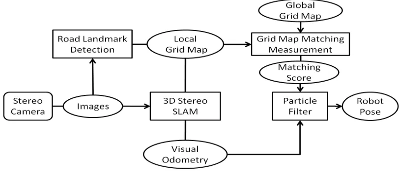
(Irie et al., 2012) proposed to address the problem of SLAM for outdoor navigation taking into consideration drastic illumination changes which happen in most environment. In this technique, stereo camera capable of obtaining 3-D range data was employed to capture data from the environment. Afterwards, 2-D grid map that is not much affected by illumination condition is generated. Given the 2-D grid map, occupancy information and salient line segment can be extracted perfectly. The particle filter is employed to extract the robot pose while edge pint based stereo SLAM was used to obtain robot ego
Matching Image-model point
Compute ViSP with data
Camera pose with drift Start/Reset RGB-D SLAM
with accurate camera pose
ViSP’s camera pose correction (VVS)
Image/Model Match (ME)
NO RGB-D SLAM
YES ViSP/RGB-D
motion and the occupancy information simultaneously. This extracted information is used to address the SLAM problem. There are other important procedures carried out to develop their technique, the model in Figure 3 provides full description of the proposed SLAM technique for mobile robot navigation in outdoor environment.
Figure 3: represent the stereo SLAM technique for mobile robot in outdoor environment (Irie et al., 2012)
The proposed model was successfully implemented and experimental performance of their visual odometry recovered from error and performed very well under various illumination situations. However, the technique failed under extremely adverse illumination condition such as when direct sunlight covers large part of the image and giving this condition, limited edge point are extracted for detection which resulted to huge error in motion estimation and inability to recover from kidnap robot.
Figure 4: the proposed monocular camera and laser scanners sensors SLAM technique (Oh et al., 2015)
At the monocular camera stage, graph structure-based technique and hybrid method which allows the SLAM technique to estimate the robot pose in ambiguity environment was proposed where laser scanner fails. In a graph-based technique, the SLAM problem using a conditional probability is expressed in (37).
xz p
z x
p i
i
(37)where xsignifies the robot pose, z
z1,...,zn
, zisignifies measurement of a sensor atth
i step while p
zi x
represent a potential function.Given this technique, experimental comparison was carried out with a conventional G-mapping approach and results revealed that their system performs better than the G-mapping approach. However, as mentioned in the section of their results, the algorithm proposed has a small computational burden because more image processing is executed when a node is added. This was also supported to be true because in the work of (Deming and Perlovsky, 2006), it was stated that data association from multiple sensors can cause the computational complexity of systems to be prohibitively high with an effect that can lead to system failure.
The study of (Clipp et al., 2009) proposed a Simultaneous Localization and Mapping (SLAM) technique using a stereo camera as the source of retrieving information from the environment. In their technique, they took into consideration the issue of computational cost and propose the use of Kanade-Lucas-Tomasi (KLT) feature tracking because of its advantage of high-speed in processing and robustness to features that are repetitive in nature; this technique was combined with a wide baseline feature which helps the system to improve its robustness to repetitive features and allows it to recognize previously visited areas in the environment. Experimental performance of the system is impressive. However, as stated in their conclusion, an item on the desk in front of the windows appeared blank due to the presence of high intensity of bright sunlight and also, the system was unable to recognize the area that has already been mapped due to movement of objects in the same area and this is as a result of low dynamic range of the system. Thus, these two problems when encountered which makes their system to fail. In the future, they plan to address this issue by extracting features in 3D scene just as it was proposed in the work of (Changchang et al., 2008). The idea is to look for ways of combining 3D geometry and sparse feature
2D laser Scanner
Monocular camera
Undistortion Operstion
Extrinsic Calibration
Ground extraction and distance
estimation from wall
Depth augmentation
Feature extraction
3D coordinate
detection with the aim of using immovable features in the image such as floor, wall and ceiling to re-localize itself regardless of dynamic changes happening in the environment. Successful implementation of this idea will allow the system to overcome the issue of dynamic environment and illumination variances
4. CHALLENGES, OPEN ISSUE AND RESEARCH DIRECTION
accuracy and SLAM runtime. Therefore, researchers are left to decide whether to reduce the accuracy of the SLAM system to decrease it computational cost or vice versa. In future, the greatest accomplishment is to attain a globally optimal solution that will address all SLAM problems. In attaining this goal, more investigation is still necessary to be carried out for proper understanding of some problem. Given a robot in real life scenario, it should be able to localize and mapped in various environment condition like in-door, out-door and under water environment. In any environment, object is often present, some objects are static while some are dynamic in nature. Therefore, SLAM technique must be capable of modeling the environment at object level, most especially in human predominant environment. Furthermore, Noises such as environmental noises (shadow and light intensity), sensors noises, gaussian noise etc all need to be eliminated to attain a SLAM technique with maximum accuracy. Even though we’ve discussed some issues that needs to be resolved to present the future SLAM. However, all problems need to be accomplished in real-time.
5. THE PROPOSED NOVEL SLAM TECHNIQUE
Over the years, researchers have proposed various SLAM technique, but they were confronted with one problem or the other. In this review, some of the problems discussed are as follows: Illumination variation, kidnap robot, dynamic environment and high computational cost. Thus, all these problems if not fully addressed can be minimize towards improving the SLAM performance. In the proposed SLAM technique, filters could be employed to minimize the effect of illumination variation of shadow and light intensity. In literature Normalize Difference Index is a common algorithm towards minimizing the effect of shadow (Agunbiade et al., 2014) while dark channel prior and OTSU thresholding algorithms are used to minimize light intensity (Agunbiade et al., 2014). These filters could be operating in parallel since we are taking into consideration the issue of high computational cost. The kidnap problem which contribute to localization failure can also be addressed by introducing into the proposed SLAM the scan to match algorithm to search for the reference map of the current observation for re-localization of the robot (Se et al., 2001). The dynamic issue can be minimized by introducing the enhanced fuzzy clustering technique for keeping track of multiple dynamic object in the environment (Walcott-Bryant et al., 2012). The SLAM algorithm is most likely to be particle based, because of it satisfactory result and acceptable performance towards computational cost. However, with the proposed novel SLAM technique possessing all these characteristics, it will offer better performance than any of the technique discussed in this review.
Conclusion
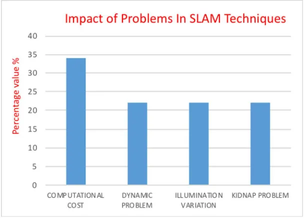
intensity and shadow), kidnap robot and dynamic environment are persistence problem mentioned by the researchers in their studies. Figure 5 shows the overall impact of these SLAM problems as related to this research.
Figure 5: The overall impact of the SLAM problems
References
1. AGARWAL, P. & BURGARD, W. 2015. Robust graph-based localization and mapping, PhD thesis,. University of Freiburg, Germany, 1-155.
2. AGHA-MOHAMMADI, A.-A., AGARWAL, S., CHAKRAVORTY, S. & AMATO, N. M. 2015. Simultaneous Localization and Planning for Physical Mobile Robots via Enabling Dynamic Replanning in Belief Space. Robotics: Systems and Control, abs/1510.07380, 1-21.
3. AGUNBIADE, O. Y., ZUVA, T., JOHNSON, A. O. & ZUVA, K. 2014. Enhancement performance of road recognition system of autonomous robots in shadow scenario. Signal & Image Processing : An International Journal (SIPIJ), abs/1401.2051, 1-10.
4. BOUTHEMY, P. 1989. A maximum likelihood framework for determining moving edges. IEEE Transactions on Pattern Analysis and Machine Intelligence, 11, 499-511.
5. CASTELLANOS, J. A., NEIRA, J. & TARDOS, J. D. 2001. Multisensor fusion for simultaneous localization and map building. IEEE Transactions on Robotics and Automation, 17, 908-914. 6. CHANGCHANG, W., CLIPP, B., XIAOWEI, L., FRAHM, J. M. & POLLEFEYS, M. 3D model
matching with Viewpoint-Invariant Patches (VIP). 2008 IEEE Conference on Computer Vision and Pattern Recognition, 23-28 June 2008 2008. 1-8.
7. CHEN, Y. 2013. Algorithm for Simultaneous Localization and Mapping. 1-15.
8. CLIPP, B., ZACH, C., LIM, J., FRAHM, J.-M. & POLLEFEYS, M. 2009. Adaptive, Real-Time Visual Simultaneous Localization and Mapping. Department of computer Science , University of Noorth Caroline, 1-8.
9. DELLAERT, F., CARLSON, J., ILA, V., NI, K. & THORPE, C. E. Subgraph-preconditioned conjugate gradients for large scale SLAM. 2010 IEEE/RSJ International Conference on Intelligent Robots and Systems, 18-22 Oct. 2010 2010. 2566-2571.
10. DEMING, R. & PERLOVSKY, L. Concurrent Detection and Tracking using Multiple, Flying, Sensors. Fourth IEEE Workshop on Sensor Array and Multichannel Processing, 2006., 12-14 July 2006 2006. 505-509.
11. DISSANAYAKE, G., HUANG, S., WANG, Z. & RANASINGHE, R. A review of recent developments in Simultaneous Localization and Mapping. 2011 6th International Conference on Industrial and Information Systems, 16-19 Aug. 2011 2011. 477-482.
12. FUENTES-PACHECO, J., RUIZ-ASCENCIO, J. & RENDÓN-MANCHA, J. M. 2015. Visual simultaneous localization and mapping: a survey. Artificial Intelligence Review, 43, 55-81. 13. GUYONNEAU, R., LAGRANGE, S., HARDOUN, L. & LUCIDARME, P. 2012. The
Kidnapping Problem of Mobile Robots: A Set Membership Approach. 7th National Conference on Control Architectures of Robots.
14. HADJI, S. E., KAZI, S. & HING, T. H. 2014. A Review: Simultaneous Localization and Mapping Algorithms for Mobile Robot. 1st International Conference of Recent in Informtion and
Communication Technologies, 83-92.
15. IRIE, K., YOSHIDA, T. & TOMONO, M. 2012. Outdoor Localization Using Stereo Vision Under Various Illumination Conditions. Advanced Robotics, 26, 327-348.
16. JIA, S., WANG, K. & LI, X. 2016. Mobile Robot Simultaneous Localization and Mapping Based on a Monocular Camera. J. Robot., 2016, 2.
17. KAESS, M., RANGANATHAN, A. & DELLAERT, F. 2008. iSAM: Incremental Smoothing and Mapping. IEEE Transactions on Robotics, 24, 1365-1378.
19. KONOLIGE, K., GRISETTI, G., KÜMMERLE, R., BURGARD, W., LIMKETKAI, B. & VINCENT, R. Efficient Sparse Pose Adjustment for 2D mapping. 2010 IEEE/RSJ International Conference on Intelligent Robots and Systems, 18-22 Oct. 2010 2010. 22-29.
20. LE CRAS, J., PAXMAN, J. & SARACIK, B. 2013. Improving Robustness of Vision Based Localization Under Dynamic Illumination. In: SEN GUPTA, G., BAILEY, D., DEMIDENKO, S. & CARNEGIE, D. (eds.) Recent Advances in Robotics and Automation. Berlin, Heidelberg: Springer Berlin Heidelberg.
21. LI-CHEE-MING, J. & ARMENAKIS, C. 2016. Augmenting ViSP’s 3D Model-Based Tracker with RGB-D SLAM for 3D Pose Estimation in Indoor Environments. Int. Arch. Photogramm. Remote Sens. Spatial Inf. Sci., XLI-B1, 925-932.
22. MONTEMERLO, M. & THRUN, S. Simultaneous localization and mapping with unknown data association using FastSLAM. 2003 IEEE International Conference on Robotics and Automation (Cat. No.03CH37422), 14-19 Sept. 2003 2003. 1985-1991 vol.2.
23. MU, B. 2013. Value of Information based distributed inference and planning. PhD Thesis, Massachusetts Institute of Technology.
24. NEGENBORN, R., JOHANSEN, P. P. & WIERING, M. 2003. Robot Localization and Kalman Filter. Institute of Information and Computing Sciences.
25. OH, T., LEE, D., KIM, H. & MYUNG, H. 2015. Graph Structure-Based Simultaneous Localization and Mapping Using a Hybrid Method of 2D Laser Scan and Monocular Camera Image in Environments with Laser Scan Ambiguity. Sensors, 15, 15830.
26. QIU, C., ZHU, X. & ZHAO, X. Vision-based unscented FastSLAM for mobile robot. Proceedings of the 10th World Congress on Intelligent Control and Automation, 6-8 July 2012 2012. 3758-3763.
27. SE, S., LOWE, D. & LITTLE, J. Vision-based mobile robot localization and mapping using scale-invariant features. Proceedings 2001 ICRA. IEEE International Conference on Robotics and Automation (Cat. No.01CH37164), 2001 2001. 2051-2058 vol.2.
28. SUJAN, V. A., MEGGIOLARO, M. A. & BELO, F. A. W. 2006. A new technique in mobile robot simultaneous localization and mapping. Sba: Controle & Automação Sociedade Brasileira de Automatica, 17, 189-204.
29. TAN, F., LOHMILLER, W. & SLOTINE, J.-J. E. 2015. Simultaneous Localization And Mapping Without Linearization. Massachusetts Insitute of Technology, abs/1512.08829, 1-50. 30. TIAN, Y. & MA, S. 2016. Probabilistic double guarantee kidnapping detection in SLAM.
Robotics and Biomimetics, 3, 20.
31. WALCOTT-BRYANT, A., KAESS, M., JOHANNSSON, H. & LEONARD, J. J. Dynamic pose graph SLAM: Long-term mapping in low dynamic environments. 2012 IEEE/RSJ International Conference on Intelligent Robots and Systems, 7-12 Oct. 2012 2012. 1871-1878.
32. WURM, K. M., STACHNISS, C., GRISETTI, G. & BURGARD, W. 2003. Improved Simultaneous Localization and Mapping using a Dual Representation of the Environment. Department of Computer Science, University of Freiburg, Germany, 1-10.
33. YINKA, A. O., NGWIRA, S. M., TRANOS, Z. & SENGAR, P. S. Performance of drivable path detection system of autonomous robots in rain and snow scenario. 2014 International Conference on Signal Processing and Integrated Networks (SPIN), 20-21 Feb. 2014 2014. 679-684.