http://www.sciencepublishinggroup.com/j/jeee doi: 10.11648/j.jeee.20190706.14
ISSN: 2329-1613 (Print); ISSN: 2329-1605 (Online)
Development of Live Working Device Based on Zero
Potential Control Principle
Xu Li
1, 2, 3, Zhu Ziqi
1, 2, 3, Yang Qi
1, 2, 3, *, Zhu Liang
4, Li Hui
1, 2, 3, Zeng Wenyuan
1, 2, 3,
Gao Quanzhe
1, 2, 3, Ou Yuexiong
1, 2, 3, Zhao Gang
1, 2, 31State Grid Hunan Transmission and Maintenance Company, Hengyang, China 2
Hunan Key Laboratory of Intelligent Live Working Technology and Equipment (Robot), Changsha, China 3
Power patrol and intelligent operation technology, State Grid Corporation Laboratory, Changsha, China 4State Grid Hunan Electric Power Co., Ltd., Changsha, China
Email address:
*
Corresponding author
To cite this article:
Xu Li, Zhu Ziqi, Yang Qi, Zhu Liang, Li Hui, Zeng Wenyuan, Gao Quanzhe, Ou Yuexiong, Zhao Gang. Development of Live Working Device Based on Zero Potential Control Principle. Journal of Electrical and Electronic Engineering. Vol. 7, No. 6, 2019, pp. 155-162.
doi: 10.11648/j.jeee.20190706.14
Received: November 4, 2019; Accepted: December 7, 2019; Published: December 12, 2019
Abstract:
In the case of live working in the distribution network, serious safety accidents will occur due to weak operation and weak safety awareness. The live working methods and equipment that meet the requirements for personal safety and power supply reliability need to be studied. In order to improve the safety of live working in distribution network, the working point zero potential control principle is proposed, and a prototype of the zero potential live operation device for distribution network is developed based on this principle. The principle and design of the charged working equipment based on the principle of zero potential control are introduced. The prototype has the functions of data collection, data analysis, logic protection and information transmission. When the selection and layout of the line conductors are different, the line parameters will also be different. For different conductor selection and layout schemes, three schemes are designed to simulate separately. The system model is established based on MATLAB, and the feasibility of the proposed method is verified by the working phase voltage curve. Experiments and third-party inspections show that the device is reliable in operation, quick in response, easy to operate, and can meet the zero potential control requirements of live working, which is of great significance to improve the safety of live working in distribution network.Keywords:
Distribution Network, Voltage Control, Live Working, Operating Device, MATLAB1. Introduction
Live working in distribution network is the most direct and effective means to improve power supply reliability and economic benefits [1]. It has been widely carried out in countries all over the world. The live working in Japan has gradually developed towards mechanization and automation, and the mechanization of live working on distribution lines will be fully realized [2-4]. The main technologies of live working of distribution network in China include: insulation protection technology, insulation tool technology, insulated bucket arm car technology, live working method of by-pass, mobile power supply operation method, etc. These
technologies ensure the safety performance of live operation to a certain extent [5-6]. Although domestic and foreign existing live work technology and tools have made some achievements, there are still some safety risks and the scope of application is limited [7-8]. Faulty operations and weak safety consciousness lead to safety accidents from time to time. Therefore, the theory and equipment of live working in distribution network need further research and development [9-12].
2. Distribution Network Working Point
Zero Potential Control Principle
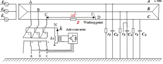
As shown in Figure 1, Suppose that live working should be carried out in C phase line of distribution network. If the
operating point voltage at this time is
. d
U , the neutral point
voltage is
. N
U , the line unit impedance is z, the voltage drop
between the power bus and the operating point is
. U ∆ .
Figure 1. Working Point Zero Potential Control Principle Diagram.
For distribution lines of 35kV and below, due to the low voltage level and small capacitance current, the concentrated series impedance can be used as the equivalent impedance of the line [13-14]. The impedance between the substation and the operating point in Figure 1 can be obtained by multiplying the unit impedance Z by the electrical distance l.
When the working phase current is
. c
I , ∆Uɺ can be obtained by Ohm's law:
. . C
U I Zl
∆ = (1)
The KVL theorem for c-phase circuits is available:
. . . .
= C
N d
U U −E + ∆U (2)
The neutral point can be obtained by using the KCL theorem:
. . . .
0 0 0
( ) ( ) ( )
i A N B N C N N L
I = E +U Y + E +U Y + E +U − ∆U Y +U Y (3)
Where,
. i
I is the current injected into the neutral point by the active inverter, Y0is earth admittance when the power grid is in normal operation, YL is ground admittance of arc suppression coil.
N
Uɺ can be expressed as:
. . . 0 0 3 i N L
I U Y
U
Y Y
+ ∆ =
+ (4)
It can be known from equation (4) that the neutral point
voltage
. N
U can be regulated when zero sequence current is
injected into the neutral point. When
. . .
C N
U = −E + ∆U , according to equation (2), the voltage at the operation point
at this time is 0
. 0
d
U = , that is, when the change of zero
sequence voltage is
. d
U , the potential at the corresponding operation point is zero. Therefore, if and only if when the zero-sequence current is injected, the amount of change in the zero-sequence voltage is adjusted to the opposite of the sum of the operating phase power supply voltage and the operating phase line voltage drop, the operating point voltage is guaranteed to be zero, creating for subsequent manual safety operations. condition.
3. Design of Zero-potential Live Working
Device for Distribution Network
3.1. Complete Device Structure
According to the zero potential control principle of the distribution network operation point mentioned above, the overall structure of the operation device is designed as shown in Figure 2. The main circuit system of the zero point potential control device researched and developed is divided into passive part and active part. The passive part is mainly capacitor group and harmonic elimination resistor. The active part is composed of the following parts: three - phase bridge type uncontrolled rectifier circuit, single-phase voltage inverter, output filter, etc.
3.2. Device Hardware Design
The device signal acquisition circuit performs real-time sampling on the neutral point voltage of the system, the voltage of each phase, and the output current/voltage of the device. After the data is processed and analyzed by DSP, the system state is determined to set the control target. The driving circuit provides the IGBT driving pulse for the inverter, and injects current to the neutral point of the distribution network to realize the control of the zero-sequence voltage (working
phase voltage) of the distribution network; The device is equipped with protective circuits that can send out signals and latches in case of termination and device failure to avoid affecting the normal operation of the system; through the touch screen display system of the device, it can realize the functions of monitoring the state quantity, modifying the parameters, and displaying the running status of the device.
Figure 2. Structure diagram of zero potential control set for distribution network operation points.
4. Device Prototype Experiment and
Detection
Accurate calculation of the injection current is used to achieve zero potential control at the operating point, and it is required to accurately measure the insulation parameters of the distribution network. Considering the influence of damping resistance on the measurement of the grounding parameters of the distribution network, a new method for measuring the capacitance of the grounding system to the ground is proposed, which can improve the accuracy of the capacitance measurement of the distribution network to the ground.
4.1. Device Prototype
Based on the overall structure of the device, a prototype of the zero-potential live working device of the distribution network was initially developed. The physical object is shown in Figure 3. The prototype is mainly composed of a control panel, a voltage source screen, and an injection transformer body box.
Figure 3. The physical drawing of the prototype.
4.2. Prototype Experiment Method
1)Experimental environment: true laboratory of 10kV distribution network
through the power distribution cabinet, voltage regulating transformer and step-up transformer, the three-phase voltage rises to about 9kV, and the three distribution network lines are: 601, 602, 603, and the capacitance capacity is about 17A.
3)Experimental method: The phase voltage was adjusted to about 5 kV, and one point of the 603 line A phase was simulated to carry out the live working, and two experiments were performed.
4.3. Experimental Results and Analysis
The following two sets of experimental data were obtained from two experiments, as shown in Table 1, Table 2:
Table 1. First set of test data.
Position Parameter Valid value before work
Valid value after work
Bus voltage
Phase A (v) 4902 170 Phase B (v) 4697 8168 Phase C (v) 4673 8289 Zero sequence (v) 158 4990 601 line Zero sequence current 0.08 2.26 602 line Zero sequence current 0.16 4.24 603 line Zero sequence current 0.32 7.64 Job point Working point current 0 0.17
Table 2. The second set of test data.
Position Parameter Valid value before work
Valid value after work
Bus voltage
Phase A (v) 5052 170 Phase B (v) 4848 8607
Position Parameter Valid value before work
Valid value after work
Phase C (v) 4825 8430 Zero sequence (v) 162 6209 601 line Zero sequence current 0.08 2.26 602 line Zero sequence current 0.16 4.53 603 line Zero sequence current 0.32 7.92 Job point Working point current 0 0.00
From the above data we can draw the following conclusions:
1)The prototype of the zero-potential live working device of the power grid can control the current of the working point to mA level in many experiments, and the effect of controlling the working phase voltage is obvious. The prototype response time is about 110ms and below; 2)At the end of the operation: the prototype device of the
zero-potential live working device of the distribution network will automatically exit after about 20s, the grid then returned to normal without manual reset.
3)The prototype of zero potential live working device in distribution network USES small signal to measure the capacitance to ground of the system, which will not affect the neutral point voltage limit and alarm.
5. Simulation Analysis
Using MATLAB to simulate the system shown in Figure 1, the model is shown in Figure 4.
Figure 4. Simulation model diagram of zero point potential non-stop operation method.
When the selection and layout of the line conductors are different, the line parameters are also different. Therefore, according to different line conductor selection and layout schemes, three schemes are designed to simulate separately.
5.1. Wire Parameter Scheme One
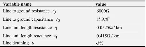
When the wire is LGJQ-600 type, the three-phase wires are horizontally arranged with a phase spacing of 0.8 m. The line parameters are shown in Table 3.
Table 3. Line parameter table of scheme one.
Variable name value
Line to ground resistance r0 6000Ω
Line to ground capacitance c0 15.9 Fµ
Line unit length resistance r1 0.0525Ω/ km
Line unit length reactance x1 0.415Ω/ km Line detuning υ -3%
has the same structure and the power supply is symmetrical, the entire system has no zero-sequence voltage zero-sequence current.
Assuming that the live working point is 3km away from the substation, the voltage waveforms of the A, B, C and neutral points are shown in Figure 5 after the current is injected.
Figure 5. Voltage waveform of scheme 1.
It can be seen from 5 that the current is injected at 1 s, and the voltage of the C phase becomes zero in a short time, which can ensure the safety of the live working personnel. At the same time, the non-working phase voltage rises to the line voltage. Since the line voltage remains symmetrical, the transmission of electrical energy is guaranteed to be unaffected by the operation. In this simulation scenario, the voltage change of each phase is consistent with the small-resistance ground fault of phase C. Due to the distribution network equipped with arc suppression coils, it is possible to operate with faults for two hours after a single-phase earth fault has occurred, which has been taken into account when selecting the insulator. Therefore, after the operating phase electrical position is zero, the non-working phase line insulator can withstand the voltage.
In Figure 1, for the C phase, the injection current does not change when the line exit point flows through the D point. The voltage amplitude of the ground voltage when the exit point of
the operation line is 0.5km, 1km, 1.5km, 2km, and 2.5km, respectively, is as shown in Figure 6.
5.2. Wire Parameter Scheme Two
Table 4. Line parameter table of scheme two.
Variable name value
Line to ground resistance r0 6000Ω
Line to ground capacitance c0 15.9 Fµ
Line unit length resistance r1 0.0525Ω/ km
Line unit length reactance x1 0.321 / kmΩ Line detuning υ -3%
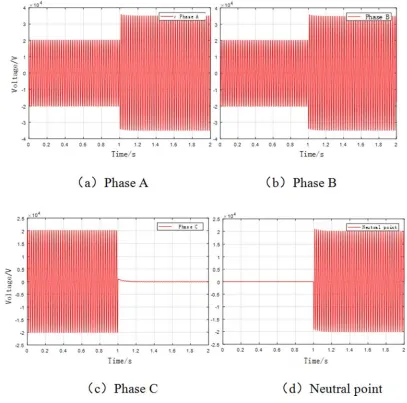
When the line is a split conductor consisting of two LGJQ-300 types, the splitting pitch is 40mm, and the line parameters are shown in Table 4.
Comparing the line unit length reactance data in Table 1 and Table 2, when the ordinary wire becomes a split wire, the line reactance value is reduced due to the increase of the equivalent radius of the split wire. In this scheme, the working phase is phase B. At 1s, the current is injected into the neutral point through the active inverter, and the voltage waveforms of the A, B, and C phases and the neutral point voltage are as shown in Figure 7.
Figure 7. Voltage waveform of scheme two.
Figure 8. The voltage distribution from the exit of the line to the operating point is in Scheme two.
The voltage amplitude of the ground voltage when the exit point of the operation line is 0.5km, 1km, 1.5km, 2km, and 2.5km, respectively, is as shown in Figure 8.
5.3. Wire Parameter Scheme Three
Table 5. Line parameter table of scheme three.
Variable name value
Line to ground resistance r0 6000Ω
Line to ground capacitance c0 15.9 Fµ
Line unit length resistance r1 0.0525Ω/ km
Line unit length reactance x1 0.279Ω/ km Line detuning υ -3%
conductors, the splitting pitch is 40mm, the phase conductors are arranged in equilateral triangles, and the phase-to-phase distance is 0.52m. The line parameters are shown in Table 5.
The phase of the selected operation phase is A phase, and
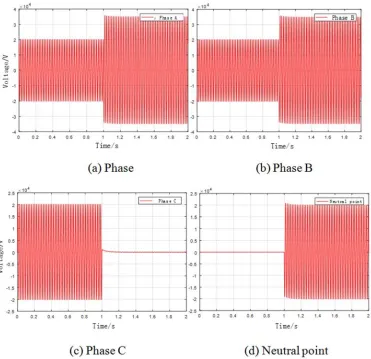
the time for injecting current is still selected as 1s. The voltage waveforms of phase A, B, and C and the waveform of the neutral point voltage are shown in Figure 9.
Figure 9. Voltage waveform of scheme three.
The voltage amplitude of the ground voltage when the exit point of the operation line is 0.5km, 1km, 1.5km, 2km, and 2.5km, respectively, is as shown in Figure 10.
Figure 10. The voltage distribution from the exit of the line to the operating point is in Scheme two.
In summary, Scheme one and Scheme two illustrate the effectiveness of the step-down of the scheme when the three-phase line is horizontally arranged or vertically
arranged, and the scheme three demonstrates the effectiveness of the scheme for the step-down when the three-phase line is in the delta connection.
6. Conclusion
The zero potential control principle of distribution network is put forward, which realizes the flexible control of the voltage from the electrified operation point to the earth, and provides an effective method to make the electric position at the operation point zero.
the reliability of power supply.
With the increasing importance of the live working of the distribution network, the device reduces the difficulty of live working in the distribution network and improves the safety of the operation. It is of great significance for actual production and can be effectively promoted.
References
[1] Hu Yi. Research and development of live working technology for transmission and distribution lines [J]. High Voltage Technology, 2006 (11): 1-10.
[2] Hu Yi, Liu Kai, Liu Ting, Xiao Bin. Research and standard setting of live working technology [J]. High Voltage Technology, 2012, 38 (11): 3015-3024.
[3] Xia Daozhi. Power System Analysis [M]. Beijing: China Electric Power Press, 2010.
[4] Wang Rong, Jiang Dong, Han Hui. The shortest path algorithm optimization algorithm based on Floyd method [J]. Journal of Gansu Sciences, 2012, 24 (04): 110-114.
[5] Zhang Dequan, Wu Guolin, Liu Dengfeng. Floyd acceleration algorithm and optimization for the shortest path problem [J]. Computer Engineering and Applications, 2009, 45 (17): 41-43+46.
[6] Zuo Xiufeng, Shen Wanjie. An Improved Algorithm for Multiple Shortest Path Problems Based on Floyd Algorithm [J]. Computer Science, 2017, 44 (05): 232-234+267.
[7] Wang Ying, Chen Song, Wang Yingying. Analysis of the Influence of Distribution Network Automation Technology on Power Supply Reliability of Distribution Network [J]. Smart Grid, 2015, 3 (03): 229-234.
[8] Xiang Hui. Discussion on hidden troubles of live working accidents in 10kV distribution network [J]. Electric Power Safety Technology, 2003 (01): 15-17.
[9] Zhou Guangfang, Tang Lihua, Chen Xuan. Working principle and protective measures of live working [J]. Science and Technology Innovation Guide, 2010 (20): 97.
[10] Lin Qi. Research on the key technology for improving the practicality of 10kV cable without power failure [D]. North China Electric Power University (Beijing), 2016.
[11] Liu Qirui. Research on uninterrupted power supply maintenance technology for distribution network [D]. South China University of Technology, 2014.
[12] Chen Wei, Lu Enqing, Chen Shitong. Design and application of live working in urban distribution network automation system [J]. Shandong Industrial Technology, 2019 (17): 149.
[13] Shi Yuliang. Analysis of the key points of safety and management of live working in distribution network [J]. Shandong Industrial Technology, 2019 (15): 183.