Interfacial heat transfer during hot metal forming operations assuming scale failure effects
M. Krzyzanowski1,2 and J.H. Beynon3
1 AGH University of Science and Technology, Faculty of Metals Engineering and Industrial Computer Science, Mickiewicza 30, 30-059 Krakow, Poland;
2 The University of Sheffield, Department of Materials Science and Engineering, Hadfield Building, Mappin Street, Sheffield S1 3JD, UK
3 The University of Adelaide, Faculty of Engineering, Computer & Mathematical Sciences, Adelaide, South Australia, 5005, Australia
Abstract
Analysis of real contact area and thermal resistance combined with experimentally derived interfacial heat transfer coefficient values, led to the development of an advanced finite element based model to simulate the heat transfer at the oxidised tool-workpiece interface during hot steel rolling. An extensive progress review and building on the Sellars 1990’s core assumptions are discussed. Today, oxide scale failure is predicted taking into account the main physical phenomena such as stress-directed diffusion, fracture and adhesion of the oxide scale. The separation loads within the scale metal/system are measured during testing. They are sensitive to the chemical composition of steel. The assumption of several parallel heat flow systems at the roll-stock interface remains the core model for today’s research.
Introduction
Knowledge of heat transfer along with friction is vital to the understanding and operation of metal forming processes. The contact conditions in metal forming processes are, to a certain extent, specific to the particular operation, and certainly very diverse. The tool-metal contact often involves large sliding lengths on which high pressures, sliding speeds and temperatures may be maintained together with plastic deformation. The plastic deformation coupled with lubrication, failure of oxide layers, creation of reactive metallic surfaces, and the constant renewal of one of the factors affecting the contact at the tool-workpiece interface, is typical for metal forming. Contact pressures can range from 1 MPa to a few 10 MPa in sheet forming processes, to a few GPa in hard metal rolling or wire drawing. Speeds vary between a few µm/s (superplastic processing) to tens of m/s (high speed drawing, turning or thin strip rolling). Surface temperatures are in the range between 0°C and 300°C in cold forming due to self heating by plastic deformation, and up to 500°C, 1300°C or even 2000°C in hot forming, depending on whether aluminium alloys, steels or refractory metals are considered [1]. The effect of these severe contact conditions is emphasised when there are high values of the aspect ratio of contact surface area to deformed volume (e.g. contact length / characteristic thickness in the rolling of flat products).
systems, lubricant delivery and the location of nozzles. The mechanical properties of the rolls and the work piece, including their resistance to deformation, all contribute here. The contributions of surface parameters, such as the chemical reactivity, the tendency to adsorb molecules from the environment, the adsorption of water vapour and oxygen, as well as surface energy, need to be taken into consideration. The nature of oxide scale formation and failure during deformation, the chemical composition of the scale and underlying metal, the adhesion between the scale and the metal surfaces in direct contact must all be taken into account. Lubrication also significantly affects the interface interactions. The chemical composition of the lubricant, the additives and their concentration in the base oil, the molecular chain length, density, viscosity and its dependence on both temperature and pressure, all should be precisely described. If emulsions are used, the composition, the emulsifier and the droplet dimensions are important. The difficulties of making laboratory measurements, combined with the complexity of events at the tool-stock interface, result in a wide range of reported values for the IHTC, Table 1 [3].
Table 1. Measured interface heat transfer coefficient (IHTC) between roll and stock for the hot rolling of steel and aluminium [after 3]
Steel Aluminium
IHTC, kW/m2K Reference IHTC, kW/m2K Reference
10 - 50 15 15 – 20 19 – 22 100 – 350 200 – 450
8 – 25 20 20 and 40
18 - 50
[4] [5] [6] [7] [8] [9] [10] [11, 12]
[13] [27]
2 - 20 5 - 50 10 – 260
18 – 38 23 – 81
200 18 40 – 75
1 – 15 400
[14] [15] [16] [17] [18] [19] [20] [21] [22] [23]
Despite all this complexity in the behaviour at the interface, it is common to represent heat transfer or friction as simple coefficients. This is done because only a limited accuracy of prediction is needed, or the required calculation is not overly sensitive to heat transfer and friction, or because the details of the interface are not well understood, so more detailed information is simply not available. There are many circumstances, however, where the success of a mathematical model depends on the appropriate formulation of the boundary conditions, which could be as sophisticated as the model itself. Of course, reasonable choices are necessary to achieve desirable precision. Including all of the above-mentioned complexities into a single mathematical model describing dependence of these two parameters is highly impractical. The model should take into consideration the most important dependencies that affect the tribological system. The parameters of the contact surfaces in hot rolling can include, for instance, the strip and roll roughness, and the thickness of the oxide scale. When lubricants are used, the viscosity and its dependence on the temperature and the pressure are taken into consideration. The concentration of the oil in the water and the droplet dimensions are considered when emulsions are applied, as in the cold rolling of steel strips.
tool-workpiece interface developed by Prof. C.M. Sellars and his collaborators in the 1990s. Not surprisingly, given Sellars’ track record, the main model assumption remains the core model for today’s research into more accurate representation of actual interface conditions. Considering the several parallel heat flow systems at the roll-stock interface as the main assumption, an advanced FE based model has been developed by his collaborators in the following years. The model has been used in this work for numerical evaluation of the interfacial heat transfer during hot metal forming operations assuming complexity of scale deformation and failure effects.
Review of IHTC model representation developed in the 1990s
The interface heat transfer coefficient ho (IHTC) is used to quantify the resistance of
an interface to the transfer of heat, usually from hot workpiece to cool tool. It is commonly defined by the equation q = ho (T2 – T1), in which T1and T2 are the temperatures on either
side of the interface, and q is the heat flux per unit area across the interface. The absence of detailed insight and a lack of fundamental understanding about the mechanism of heat transfer at a moving interface has led most modellers to assume an average, constant value of the heat transfer coefficient.
The contacting points between two surfaces serve as paths of lower resistance for heat flow in comparison to adjacent regions where heat transfer occurs across air gaps [24]. It has been assumed that the link between friction and heat transfer at the interface is the fraction of the total area, εA, the area that is in direct contact. The real contact area depends on both the
interfacial pressure, p, and the shear strength, kshear, in the real contact zone:
A shear
c k
m
p (1)
where mc is an empirical constant within the range of 0 to 1 and μ is the friction coefficient at
the interface [25]. Observations made through pilot mill tests on a 316L austenitic stainless steel shown that the variation in IHTC with reduction, rolling speed and lubrication could be explained on the basis of the influence of these rolling parameters on fractional contact area [26]. The observed increase in the IHTC during rolling was explained by the increase in pressure at the roll stock interface that led to an increase in the real area of contact between two surfaces. The influence of rolling reduction, rolling temperature, roll speed, roll and workpiece mechanical properties and surface roughness can be related to their effect on roll pressure. It has been found that the mean IHTC is linearly related to mean pressure (Fig. 1) [28]. This relationship can be used in industrial rolling to determine the magnitude of the IHTC from an estimate of the rolling load. The estimations exhibited that the heat losses to the work rolls during the early passes in hot rolling can be more than 30% of the total, showing the importance of accurately characterizing the IHTC in the roll bite.
transfer within the roll gap consists of two parallel heat flow systems: through the oxide
scale – a “two-layer zone”, and directly between the roll/fresh metal interface, a “one layer zone”, representing the total thermal resistance over the entire apparent contact area by the following equation:
2
1 e
ox e
s e a
R A R
A R A
(2)
where Aa, As and Aox are the overall apparent contact area, and the apparent areas occupied by
the extruded fresh steel and by the oxide scales in the roll gap, respectively, and Re is the
thermal resistance of the various interfaces.
Then, the effective IHTC, Ce,can be derived from eq. (2) as
s
e s e
e C C
C 1 2 1 (3)
where Ce1 and Ce2 are the heat transfer coefficients for the “one layer” and “two layer” zones,
respectively. The term αs is the area fraction of the gaps formed from the through-thickness
cracks at the interface and filled with fresh metal and is defined as αs = As / Aa. In order to
obtain the effective IHTC for the entire rolling pass, it is therefore necessary to obtain not only the HTC components for the individual contact zones and thermal barriers, but also to know the mean area fraction of the fresh steel in the roll gap. At that stage of understanding the micro events within the oxide scale metal system, the mean area fraction of the fresh steel extruded through the gaps within the oxide scale was estimated using the following consideration. First, a mean rolling reduction em is determined thus:
l l
slab x x
m dx
h h l
dx e l e
0 0 0
1 1 1
(4)
where l is the horizontally projected length of the contact arc determined approximately by R
h
l slab , and hx is the instantaneous thickness of the slab at the coordinate x of the
deformation zone:
2
1 2 1 1
R x R
h
hx . (5)
Substituting eq. (5) into eq. (4) and integrating yield
R h h e slab slab m 8 1 3 2 0
. (6)
Thus, the mean slab thickness corresponding to the mean reduction is defined as hm = ho slab(1
– em) and volume of the deformation zone V can be determined as V = lhmbm, where bmis the
mean width of the slab in the deformation zone. Assuming volume constancy of the slab during rolling, the mean area fractions of the scale layer αox and fresh steel αs in the
deformation zone can be determined correspondingly as
R h h e slab o slab m ox 8 1 3 2 1 1
(7)
and R h h slab o slab ox s 8 1 3 2 1
(8)
where ∆hslab is the absolute reduction in the thickness, ho slab is the initial slab thickness and R
is the roll radius [31]. Thus, the effective IHTC depends on HTCs for the individual contact zones and thermal barriers:
s
b ox b ox s e e C C C C C
C
1
2 2
1 (9)
where Cb2 is the HTC for the partial contact at the “two layer zone”, usually called contact
conductance, and Cox is the HTC through the oxide scale. The coefficient Cox was
approximately obtained for the given oxide scale thickness δox and the scale thermal
conductivity kox using the following equation:
. ox ox ox k C
(10)
No systematic analysis appears to have been conducted for quantitative variations of the contact conductance with surface, interface and deformation conditions during metal forming operations. It was assumed that, in addition to the surface roughness and thermal conductivity of two contacting solids under normal static contact conditions, the contact conductance is related to the apparent contact pressure, pa, and the hardness of the softer contacting material,
HV, [32-34]. This relationship and also the relationship between the degree of real contact and the dimensionless contact pressure obtained on the basis of experimental measurements and mathematical analysis [35, 36] led to establishment of the exponential relationship between the contact conductance and the contact pressure during hot rolling [31]. The same contact and heat transfer states at the scale layer/tool interface were assumed for forging and rolling. Accordingly, the contact conductance for a “two-layer zone” Cb2 during hot steel
rolling can be calculated by using the following equation that was developed earlier for hot forging of steel:
B ox a a h b HV p R A C
2 1 exp 0.3 2
(11)
mean of the thermal conductivity of the oxide scale λox and the steel roll λr and is determined
by
1 1 1 /2
2
ox r
h
(12)
The oxide scale grown on low carbon steels can be considered as a brittle material at elevated temperatures up to 800oC and its relevant behaviour also depends on the strain rate. Vickers hardness measurements can cause cracks in the oxide layer, so only measurements in the middle of the oxide layer are possible. The Vickers hardness of the oxide scale, HVox, was
assumed to vary with the surface temperature of the oxide scale Toxs according to the
following equation developed on the basis of interpolation of the available experimental data [37]:
K T K
T
HVox 7075 538 oxs 293 oxs 1273 (13) For a case of low pressure, the equation (5) is replaced by the simpler version:
. 3
. 0 2 2
B
ox a a
h b
HV p R
A
C
(14)
For the rolling conditions where the initial rolling temperature is around 1000oC, the scale thickness is within the 25 – 700 μm range, the rolling reduction is between 10 and 50% and the corresponding average rolling pressure is between 130 and 200 MPa, the contact conductance of a “one layer zone” is calculated using the same equations (eq. 11 and 14) where the constants A and B are set to 0.405 and 1.5 respectively, and the parameter λh2 is
replaced by λh1. The parameter λh1 is the harmonic mean of the thermal conductivity of the
roll material, λr, and the specimen material, λs, and is determined by 1/λh1 = (1/λr + 1/λs)/2.
HVs is the Vickers hardness of the fresh steel specimen.
A physically-based FE oxide scale model considering scale failure effects
The oxide scale model is usually a meso-part of a more complex multilevel FE model [38, 39]. The model can be included into and run simultaneously with a macro model representing either a technological operation or a testing procedure. The thickness of the secondary oxide scale, usually about 10 – 100 μm, is relatively small with respect to the macro model. The oxide scale model has the capacity to include very fine features such as multi-layer scale, voids or a complicated profile of the scale/metal interface (Fig. 3).
a b
Fig. 2 The IHTC during steel hot rolling predicted for the different scale thickness (a) and rolling reduction (b) at initial temperature about 1000oC [31].
The finite elements should have similar sizes at the contact regions and the increment load should be adequate to the element sizes being in contact so as to avoid the numerical obstacles. It becomes difficult to satisfy the above criteria in a single model. Hence, corresponding linking of modelling scales is a necessary stage for prediction of scale behaviour during modelling of both mechanical testing and technological operations. The oxide scale is simulated as comprising numerous scale fragments joined together to form a scale layer, covering the representative raft length. To be able to reflect the real crack pattern observed during the hot rolling pass, the length of each oxide scale fragment is chosen to be less than the smallest spacing of cracks observed in the experiments. The predicted crack spacing should be insensitive to the sizes of the scale fragments. They are chosen randomly, enabling prediction of representative crack spacing and distribution of cracks along the length of the raft due to both longitudinal tension and contact with the roll. Oxide scale failure is predicted by taking into account the main physical phenomena such as stress-directed diffusion, fracture and adhesion of the oxide scale, strain, strain rate and temperature (Table 1). The main mathematical assumptions of the model related to oxide scale are presented in Table 2. The other relevant details of the model can be found elsewhere [39, 40, 48].
Table 1. Properties of oxide scale and scale/metal interface used for calculation [after 39]
Parameter Function Ref.
Density, kg/m3
= 5.7x10³ Ranta et al., 1993
Specific Heat Capacity, J/kg deg cp = 674.959+0.297*T-4.367*10 -5*T
for T 600 – 1100oC
Ranta et al., 1993
Thermal Conductivity, W/mK = 1+7.833*10-4*T
for T 600 – 1200oC
Ranta et al., 1993
Young’s Modulus, GPa E = Eoxo (1 + n (T-25))
n = - 4.7x10⁻⁴; E
oxo = 240 GPa;
Morrel, 1987
Poisson’s Ratio = 0.3 Robertson and
Manning, 1990
Heat transfer coefficient at oxide/metal interface, W/m2K
= 30000 Pietrzyk and
Lenard, 1991
Surface diffusion coefficient times effective surface thickness, m3/s
SDS = SDoS exp(-QS / RT)
SDoS = 1.10*10-10 m3/s; QS = 220
kJ/mole
Swinkels and Ashby, 1981
Volume (lattice) diffusion coefficient, m2/s
DV = DoV exp(-QV / RT)
DoV = 1.80*10-4 m2/s; QV = 159
kJ/mole
Swinkels and Ashby, 1981
Stress intensity factor, MN m-3/2 K = a
o+a1T+a2T2+a3T3+a4T4+a5T5
for 20 – 820oC
ao = 1.425; a1 = -8.897*10-3;
a2 = -8.21*10-5; a3 = 3.176*10-7;
a4 = -5.455*10-10; a5 = 3.437*10-13
1 k1
rel
v
1
rel
v Table 2. Oxide scale model assumptions [after 39]
Assumption Equation Reference
Stress-directed diffusion of metal atoms round interface irregularities controls the rate of viscous scale sliding
Riedel, 1982
Dislocation creep in addition to diffusional flow of atoms can circumvent interface irregularities
Riedel, 1982
Critical strain for through-thickness crack depends on fracture surface energy, Young’s modulus, the shape and position of the void, the composite void size
Schütze, 1995
The viscosity coefficient depends on the temperature, atomic volume, the diffusion coefficients, the interface roughness
Raj and Ashby, 1971
It was assumed that spalling of the scale could occur along the surface of lowest energy release rate, which can be either within the scale or along the scale/metal interface. A flaw will continue to grow under a stress, if its energy release rate G exceeds the critical energy release rate Gcr. The availability of experimental data exhibited that through-thickness
cracking is an essentially brittle process of unstable crack propagation for the majority of cases. It favoured the assumption of linear elastic fracture mechanics for the model that is acceptable for prediction of scale failure for such cases. Assuming the opening of the through-scale crack due to applied tension loading perpendicular to the crack faces (tensile mode), the critical failure strain cr may be used as a criterion for a through-thickness crack
occurring. Tangential viscous sliding of the oxide scale on the metal surface is allowed, arising from the shear stress transmitted from the specimen to the scale in a manner analogous to grain-boundary sliding in high-temperature creep. Tangential viscous sliding of the oxide scale over the metal surface due to the shear stress transmitted from the steel is allowed when the scale and the metal surface are adherent. This kind of viscous sliding is different to frictional sliding of the separated scale fragment when separation stresses are exceeded.
In some cases, steel oxides can show both brittle failure at temperatures below about 800oC and signs of ductile fracture at higher temperatures. At high strain rates the failure can become brittle even at high temperatures. Experimental observation of the ductile fracture within the oxide sale favours the important conclusion that the model should be able to accommodate both types of failure. For the former, the critical strain for failure is implemented into the model, while the J-integral is used as a parameter corresponding to the strain energy release rate for consideration of ductile scale failure. Path independence of the J-integral can be proved for non-elastic material behaviour. Provided that the actual elastic-plastic material behaviour resembles this non-linear elastic behaviour, the J-integral can also be used to evaluate the stress and strain field near the cracks in elastic-plastic material. Determination of the crack length is based on increment number and deactivation of the separation forces based on the crack length and J-integral value. It has been assumed that
no-Ec F
c
22) 4 / (
8
2 _ _
V
s D
singularity modelling near the crack tip is applicable, with a quarter-point node technique and only one contour for the J-integral specified for each interface. The derivatives of elements of the inverse Jacobian J-1 and of the determinant of the Jacobian [J] are only considered in the applied virtual crack extension method.
01
dV J u J J
W W
o
V k
i jk ij e
, (15)where the symbols have their usual meaning. The MSC/MARC commercial finite element code is used to simulate metal/scale flow, heat transfer, viscous sliding and failure of the oxide scale during hot rolling, assuming the plane strain condition. The release of nodes is organized with user-defined subroutines in such way that the crack length is determined based on the increment number then, according to crack length, the boundary conditions are deactivated by calling a routine for a specific node number.
Fig. 4 illustrates the gap patterns typically formed in the oxide scale at entry into the roll gap and within the roll gap. The gaps have different lengths because of their different origin. Some relatively big gaps formed from through-thickness cracks developed at the entry zone due to longitudinal tensile strain in that area. Other gaps, usually small, formed due to bending at the roll bite. The small gaps can become even narrower during passage through the roll gap. The gap between scale fragments is changed under the roll compression because of sliding and deformation of the oxide scale and metal extrusion through the gap. Crack closure eliminates or reduces the metal extrusion and improves the product’s surface finish. It has been shown that among the main factors influencing the degree of metal extrusion during compression are the temperature and the initial width of the gap [41]. The scale slides at high temperatures making the initial gap smaller or closed. However, if the initial gap is relatively big the gap width is increased during the deformation.
Numerical evaluation of IHTC during steel hot rolling – results and discussion As can be seen in Fig. 4, the apparent contact surface in the roll gap consists of the three types of zones: the roll and stock oxide scale zone, and two non-scaled zones forming
gaps between stock scale fragments. Some gaps can have direct contact between the roll surface and extruded hot metal. This behaviour of the oxide scale and fresh steel allows for the assumption that there are three parallel channels (zones) for the heat from the high temperature stock to be transferred to the low temperature rolls. In the first zone, the heat is transported through the scale layer, the boundary gap due to partial contact between roll and scale and, possibly, the roll scale. In the second zone, the heat is transported through the boundary gap developed between the oxidised roll and the steel surface. The third zone is formed when the extruded metal has a direct contact with the relatively cold surface of the roll. In such a case, the heat is transferred through the gap as well as through the direct contact. The boundary gap due to partial contact between roll and the fresh metal is also assumed for the third zone. As can be seen (Fig. 4), the FE model results are in good agreement with the main representations of Prof. C.M. Sellars and his collaborators developed in the 1990s considering the several parallel heat flow systems at the oxidised roll-stock interface. The advanced FE based model just allows for improvement of evaluation of the IHTC during metal forming operations assuming complexity of deformation in the area and evolving scale failure effects. The model has been upgraded with experimental data related to low carbon steel oxides obtained during hot tensile testing of the steel specimens of the following chemical content (wt%): 0.18C, 0.26Si, 0.95Mn, 0.03Cr, 0.05Ni and 0.1Cu. Matching the predicted and measured loads at the head of the specimen, as it is described elsewhere [42], the separation loads within the scale and at the scale/metal interface were implemented into the oxide scale model for evaluation of the IHTC. It is assumed in the model that the surface geometry of the roll does not change significantly during the rolling pass. The roll surface roughness is measured and included in the numerical analysis while the scale surface is assumed to be flat. The total thermal resistance, Re, over the apparent contact
area can therefore be determined as
3 3 2 2 1 1 e e e e a R A R A R A R A
(16)
where Aais apparent contact area and A1, A2 and A3 are apparent areas occupied by the scale,
gaps and extruded metal.
i i
A
A1 1 , i - number of the scale fragments;
j j
A
A2 2 , j –
number of gaps and
k k
A
A3 3 , k – number of the direct contact zones. Eq. (16) is similar
to eq. (2) with the difference that the three heat flow channels are considered. The effective IHTC at the arc of contact is therefore determined as a sum of the heat transfer coefficients Cei determined within the corresponding zones
3 3 2 2 1
1 e e e
e C C C
C (17)
where αi = Ai/Aa is the area fraction of the corresponding zones: the scale, the gap and the
extruded metal zone, such that α1 + α2 + α3 = 1. Assuming no scale on the roll surface, the
heat transfer coefficient through the scale (zone 1), Ce1, is determined as
1 1 1 b ox b ox e C C C C C
(18)
where Cox is the heat transfer coefficient through the oxide scale layer and Cb1 is the heat
transfer coefficient due to partial contact at the boundary gap (Fig. 5). This is usually called contact conductance. The heat transfer coefficient through the scale layer is determined as
) ( ) ( a ox ox ox p T k C
where kox is the thermal conductivity of the scale depending on the temperature, T, and δox is
the scale thickness, which depends on the pressure pa. The temperature dependence of the
thermal conductivity is calculated as
T T
kox( )17.833104 (20) within the temperature interval from 600oC to 1200oC [43]. In the case when the roll scale cannot be neglected in terms of the heat transfer, the eq. (11) can be rewritten as
1 1 1 1 b ox b Rox ox Rox Rox b ox e C C C C C C C C C C
(21)
where CRox is the heat transfer coefficient through the roll scale layer determined as
) ( ) ( a Rox Rox Rox p T k C
(22)
where the parameters kRox and δRox have the same meaning as in the eq. (16) but related to the
roll’s oxide scale. The contact conductance parameter, Cb1, has proved to be difficult to
determine. No systematic measurements or analyses have been found for the quantitative variations with surface, interface and deformation conditions during metal forming conditions. It has been assumed that the contact conductance, in addition to the effects of the surface roughness and the thermal conductivity of two contacting materials, is related to the apparent contact pressure pa and the hardness, HV, of the softer material in the contact, as it
was adopted earlier by Li and Sellars [31] and expressed by eq. (11) – (14).
For zone 2, when there is no direct contact between solids, the heat transfer coefficient Ce2 depends on the roll oxide thickness, lubricant thermal conductivity and other
parameters. It was assumed to be negligibly small in this analysis. For zone 3, the heat transfer coefficient Ce3 is determined as
s
e s b
e C C
C 3 3 2 1 (23)
where βs is the degree of the fresh steel contact. The contact conductance Cb3 between
extruded fresh steel and the roll surface is determined from eq. (9) and (12), assuming A3 =
0.405 and B3 = 1.5. The harmonic mean of the thermal conductivity of the roll and specimen
steel, kh3, is determined as shown in eq. (2). The Vickers hardness of the fresh plain carbon
steel, HV3, is calculated approximately by using the flow stress σs at 8% strain, neglecting
work hardening [44]:
s
HV3 3 (24)
The degree of the fresh steel contact βs is determined as the ratio between the length of the
fresh steel contact and the length of the gap in the oxide scale formed at the arc of contact during the rolling pass (Fig. 5). It has to be noted that the parameter βsis changed during the
rolling pass depending on many technological parameters such as temperature, scale thickness, chemical composition of the steel, gap width at entry into the roll gap, rolling
Fig. 5 Temperature distribution predicted at the area of the fresh steel contact with the roll surface.
0.3 mm Oxide scale
Roll
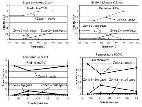
reduction, etc. The area fraction αi of the corresponding zones the scale (i = 1), the gap (i = 2)
and the extruded metal zone (i = 3) is changed during the rolling pass and depends, among others, on the initial stock temperature and the oxide scale thickness, as can be seen in Fig. 6. The gaps within the oxide scale are formed at lower temperatures and higher reductions. It can be explained by the fact that the scale /metal interface of the low carbon steel becomes weaker at higher temperatures and the scale tends to slide along the interface rather than cracking in the through-thickness mode. Thicker scale, of about 100μm thickness for instance, exhibits more tendency towards crack development during the rolling pass rather than thinner scale layers about 10-30μm thick.
The heat transfer coefficient through the scale layer, Cox, is also changed during the
rolling pass, mainly because of changes in the thermal conductivity of the scale, kox, and the
scale thickness, δox, depending on the temperature, type of the oxide scale and the rolling
These changes will affect the heat transfer coefficient through the oxide scale layer according to eq. (19). The degree of fresh steel contact, βs, is changed during the rolling pass due to steel extrusion within the gap between the scale fragments and among other rolling parameters, such as the scale thickness and temperature, depends to a large extent on the initial gap width
Scale thickness 0.1mm Scale thickness 0.1mm
Temperature 800oC Temperature 800
oC
Fig. 6 Effect of the initial stock temperature and oxide scale thickness on the area fraction of the scale failure zones predicted for the different rolling reductions.
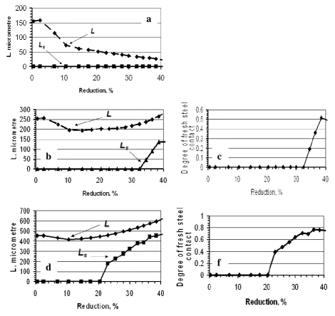
at entry into the roll gap and the rolling reduction. As can be seen in Fig 8a, the small gaps, formed presumably due to bending at the roll bite, tend to close during further compressive deformation within the arc of contact during a rolling pass and there is no contact between the roll surface and fresh stock steel observed. As the initial gap becomes wider, the gap narrows until about 10% reduction. Then, at higher reductions, the gap widens, allowing fresh steel to be extruded into the gap under the roll pressure. The first direct contact between fresh steel and the roll surface occurs at about 20-30% reduction, depending on the initial gap width, and the degree of fresh steel contact increases up to a fraction of about 0.5-0.8 at 40% reduction (Fig. 8b – f). These changes in the degree of fresh steel contact lead to significant changes in the ITHC calculated for the different reductions, as shown in Table 3.
Fig. 8 Effect of the rolling reduction on the gap width L (a, b, d) and degree of fresh steel contact βs (c, f) predicted for the different gap width at entry into the rolling pass
and the initial temperature T = 1000°C.
a
b
c
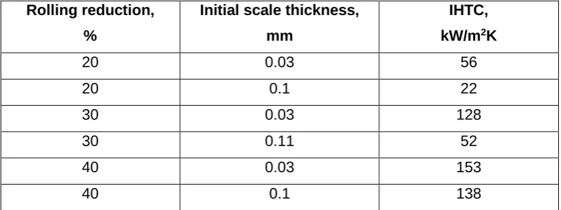
Table 3. Effect of the rolling reduction and the initial oxide scale thickness on IHTC predicted at the initial temperature of 800oC
Rolling reduction, %
Initial scale thickness, mm
IHTC, kW/m2K
20 0.03 56
20 0.1 22
30 0.03 128
30 0.11 52
40 0.03 153
40 0.1 138
Quantitative characterization of heat transfer at the workpiece/tool interface during hot metal forming operations is still inconsistent and in most cases creates a major handicap to producing accurate and reliable models for hot metal working processes. The reason for this is partly because of the complicated physical phenomena taking place in the contact. Along with complicated secondary oxide scale behaviour, the importance of surface roughness and lubrication effects on IHTC in the hot rolling of steel has been widely recognized [45]. The strain imposed on the steel surface when stock enters the roll gap, because of drawing in by frictional contact with the roll, produces longitudinal tensile stresses ahead of the arc of contact, which may result in oxide failure. The fractured scale, which has a thermal conductivity about 10-15 times less than the steel, can enable direct contact of hot metal with the cold roll due to extrusion through fractured scale up to the cool roll surface [46]. Such spaces, distributed along the arc of contact, will increase the IHTC through the oxide thermal barrier, as discussed above. However, at higher temperatures the oxide metal interface is weaker than the oxide and shear stresses cannot be fully transmitted to the oxide raft due to sliding, which complicates the crack pattern formation [47]. The location of the plane of sliding is determined by the cohesive strength at the different interfaces within the steel-inhomogeneous oxide scale and by the stress distribution when delamination within the scale takes place. A major problem is high sensitivity of properties and morphology of both the scale itself and the interfaces to the chemical content of steel and the conditions of their growth. Despite considerable complexity, a combination of careful experiments and detailed finite element (FE) analysis has been successfully applied to represent a wide range of the observed physical phenomena [48] and numerical characterization of these phenomena can be achieved using the physically-based FE model briefly described in this section. Although the results presented above are mainly for carbon steels, the method can be applied to other technologically important alloys such as stainless steels and aluminium alloys.
Conclusion
predicting the micro events at the roll/stock interface affecting the IHTC, such as those suggested by Prof. C.M. Sellars and his collaborators in the 1990s. Of course, reasonable choices are necessary to achieve desirable precision; they should take into consideration the most important dependencies that affect the tribological system. Sellars was adept at such choices thanks to the tremendous physical insight that characterised his research.
Acknowledgement
The authors would like to express their deep gratitude to Professor Christopher Michael (Mike) Sellars (deceased) for his leadership, teaching and companionship over many years of research together. Mike was a researcher of great insight, effortlessly blending scientific rigour with industrial relevance to produce results of importance and value to both the academic and industrial communities around the world. The contribution of Dr Y.H. Li from GE Energy Management UK and the support from the National Science Centre Poland (grant no. DEC-2013/09/B/ST8/00141) are highly appreciated.
Literature
1. J.A. Schey, Metal deformation processes: friction and lubrication, Marcel Dekker, New York, 1970
2. J.A. Schey, Tribology in Metalworking, Friction, Lubrication and Wear, The American Society for Metals, Metals Park, Ohio, 1983
3. J.H. Beynon, Modelling of friction and heat transfer during metal forming, KomPlasTech’99, 17-20 January, (Szczyrk, Poland), 1999, p 47-54
4. B.K. Chen, P.F. Thomson and S.K. Choi, Temperature distribution in the roll-gap during hot flat rolling, J. Mater. Proc. Technol., Vol. 30, 1992, p 115-130
5. S.P. Timothy, H.L. Yiu, J.M. Fine and R.A. Ricks, Simulations of single pass of hot rolling deformation of aluminium alloy by plane strain compression, Mat. Sci. Tech., Vol. 7, 1991, p 255-261
6. S.L. Semiatin, E.W. Collings, V.E. Wood and T. Altan, Determination of the interface heat transfer coefficient for non-isothermal bulk forming process, Trans. ASME, J. Eng. Ind., Vol. 109, 1987, p 49-57
7. M. Pietrzyk, J.G. Lenard, A study of thermal mechanical modelling of hot flat rolling, J. Mater. Shaping Technol., Vol. 7, 1989, p 117-126
8. C.O. Hlady, I.V. Samarasekera, E.B. Hawbolt and J.K. Brimacombe, Heat transfer in the hot rolling of aluminium alloys, Int. Symp. On Light Metals Processing and Applications; 32nd Annual Conf. of Metallurgists CIMM, Bickert C. et.al., Eds., 1993, p 511-522
9. C.O. Hlady, J.K. Brimacombe, I.V. Samarasekera and E.B. Hawbolt, Heat transfer in the hot rolling of metals, Met. & Mat. Trans. B., Vol. 26B, 1995, p 1019-1027
10.Y.H. Li, C.M. Sellars. Evaluation of interfacial heat transfer and its effects on hot forming processes. Ironmaking Steelmaking, 23 (1996), p 58–61
11.M. Pietrzyk, C. Roucoules and P.D. Hodgson, Modelling the thermomechanical and microstructural evolution during rolling of a Nb HSLA steel, ISIJ Int. 35 (5) (1995), p 531-541
13.M.P. Phaniraj, B.B. Behera and A.K. Lahiri, Thermo-mechanical modelling of two phase rolling and microstructure evolution in the hot strip mill. Part 1. Prediction of rolling loads and finish rolling temperature, J. Mater. Proc. Technol., Vol. 170, 2005, p 323-335
14.Z. Malinowski, J.G. Lenard and M.E. Davies, A study of heat transfer coefficient as a function of temperature and pressure, J. Mater. Proc. Technol., Vol. 41, 1994, p 125-142 15.M. Pietrzyk and J.G. Lenard, A study of boundary conditions in hot/cold flat rolling, Int.
Conf. Computational Plasticity: Models, Software and Applications, Proceedings, D.R.J. Owen et al., Eds., (Wales), Pineridge Press, 1989, p 947-958
16.W.C. Chen, I.V. Samarasekera and E.B. Hawbolt, Characterisation of the thermal field during rolling of microalloyed steels. 33rd Mechanical Working and Steel Processing Conf., Proceedings, Vol. XXIX, (USA), Iron & Steel Soc., 1992, p 349-357
17.P.G. Stevens, K.P. Ivens and P. Harper, Increasing work-roll life by improved roll-cooling practice, J. Iron Steel Inst., Vol. 209, 1971, p 1-11
18.K. Murata, H. Morise, M. Mitsutsuka, H. Haito, T. Kumatsu and S. Shida, Heat transfer between metals in contact and its application to protection of rolls, Trans. ISIJ, Vol. 24, 1984, p B309
19.C.M. Sellars, Computer modelling of hot working processes, Mat. Sci. Tech., Vol. 1, 1985, p 325-332
20.X. Duan and T. Sheppard, Influence of forming parameters on static recrystallization behaviour during hot rolling aluminium alloy 5083, Modelling Simul. Mater. Sci. Eng. Vol. 10, 2002, p 363-380
21.Y. Kang, Y. Liu and Y. He, An experimental and numerical study of heat transfer coefficient in deformation zone during hot rolling of aluminium alloy, Proc. Int. Conf. on Mechanic Automation and Control Engineering (MACE), 26-28 June 2010, Wuhan, Publ. IEEE, 2010, p 5789-5791
22.A. Saxena and Y Sahai, Modeling of fluid flow and heat transfer in twin-rolled casting of aluminium alloys, Materials Transactions, Vol. 43, No. 2, 2002, p 206-213
23.T. Yoneyama, H. Asaoka, H. Kimura, I. Hoshino and M. Kokubo, Heat transfer and roll surface temperature in the hot rolling of aluminium sheet, Journal of Tribology, Vol 121, 1999, p 753-760
24.W.C. Chen, I.V. Samarasekera, A. Kumar, E.B. Hawbolt, Mathematical modeling of heat flow and deformation during rough rolling, Ironmaking and Steelmaking, Vol. 20(2), p 113-125
25.T. Wanheim and N. Bay, A model for friction in metal forming processes, Ann. CIRP, Vol. 27 (1), 1978, p 189-193
26.C. Devadas, I.V. Samarasekera and E.B. Hawbolt, The thermal and metallurgical state of steel strip during hot rolling: Part 1, Characterization of heat transfer, Metall. Trans. A., Vol. 22A, 1991, p 307-319
27.W.C. Chen, I.V. Samarasekera and E.B. Hawbolt, Fundamental Phenomena Governing Heat Transfer During Rolling, Metall. Trans. A, Vol. 24A , 1993, p 1307-1320
29.J. Ball, J.A. Treverton and M.C. Thornton, Evaluation of the effects of stresses in hot rolling mills on oxide films on aluminium, J. Soc. Trib. Lub. Engrs., Vol. 50, 1994, p 89-93
30.Y.H. Li and C.M. Sellars, Comparative investigations of interfacial heat transfer behaviour during hot forging and rolling of steel with oxide scale formation, J. Mater. Proc. Technol., Vols. 80–81, 1998, p 282–286
31.Y.H. Li and C.M. Sellars, Modelling deformation behaviour of oxide scales and their effects on interfacial heat transfer and friction during hot steel rolling, 2nd Int. Conf. On Modelling of Metal Rolling Processes, Proceedings,J. H. Beynon, P. Ingham, H. Teichert and K. Waterson, Eds.,(London,UK), The Institute of Materials, 1996, p 192-206
32.M.G. Cooper, B.B. Mikic and M.M. Yovanovich, Thermal contact resistance, Int. Heat Mass Transfer, Vol. 12, 1969, 279-300
33.M. Bahrami, J. R. Culham, M. M. Yovanovich, and G. E. Schneider, Thermal Contact Resistance of Nonconforming Rough Surfaces Part 1: Contact Mechanics Model, Journal of Thermophysics and Heat Transfer, Vol. 18, No. 2, 2004, p 209 - 217
34.M. Williamson and A. Majumdar, Effect of surface deformations on contact conductance, Trans. ASME: J. Heat Transfer, Vol. 114, Nov. 1992, 802-809
35.J. Pullen and J.B.P. Williamson, On the Plastic Contact of Rough Surfaces, Proc. R. Soc. London, Ser. A, A327, 1972, 159-173
36.B.B. Mikic, Thermal contact conductance: theoretical considerations, Int. J. Heat Mass Transfer, Vol. 17, 1974, 205-214
37.G.V. Samsonov, The Oxide Handbook, IFI/Plenum, New York, 1973
38.M. Krzyzanowski, W.M. Rainforth, Oxide modelling in hot rolling: assumptions, numerical techniques, examples of predictions, Ironmaking & Steelmaking, 37, No 4, 2010, 276-282
39.M. Krzyzanowski, J.H. Beynon and C.M. Sellars, Analysis of secondary oxide scale failure at entry into the roll gap Metallurgical and Materials Transactions B, Vol. 31B (2000) 6, 1483-1490
40.M. Krzyzanowski, P. Suwanpinij, J.H. Beynon, Analysis of crack development, both growth and closure, in steel oxide scale under hot compression, Materials Processing and Design: Modelling, Simulation and Applications, NUMIFORM 2004, (eds S. Ghosh, J.C. Castro and J.K. Lee), American Institute of Physics, 712, Melville, New York, 2004, 1961-1966
41.J.H. Beynon, M. Krzyzanowski, N. Taranets, Surface scale evolution in the hot rolling of steel, Invited Keynote at “HSLA Steels 2005 and ISUGS 2005”, 8-10 November, Sanya, Hainan, China, Proceedings of 5th International Conference on HSLA Steels “HSLA Steels 2005”,Iron and Steel Supplement, 40, 2005, 83-90
42.M. Krzyzanowski, J. H. Beynon, Measurement of oxide properties for numerical evaluation of their failure under hot rolling conditions, Journal of Materials Processing Technology, vol. 125-126, 2002, 398-404
43.H. Ranta, J. Larkiola, A.S. Korhonen, A. Nikula, A Study of Scale-Effects During Accelerated Cooling, Proc. 1st Int. Conf. on ‘Modelling of metal rolling processes’, September 1993, London, UK, The institute of Materials, UK, 1993, 638-649
45.M. Krzyzanowski and J.H. Beynon, Oxide behaviour in hot rolling, in Metal Forming Science and Practice, (ed J.G. Lenard), Elsevier, 2002, pp. 259-295
46.Beynon, J.H. (1998) The impact of tribological issues of energy conservation in metal forming operations, Proceedings of the 24th Leeds-Lyon Symposium on Tribology, (ed D. Dowson), Elsevier Science BV, London, pp. 327-33
47.M. Krzyzanowski and J.H. Beynon, The tensile failure of mild steel oxides under hot rolling conditions, Steel Research, 70 (1), 1999, 22-27
![Fig. 1 Relationship between the mean roll pressure and the mean heat transfer coefficient during hot rolling of low carbon, stainless and microalloyed steel [28]](https://thumb-us.123doks.com/thumbv2/123dok_us/1010008.1600911/4.595.76.409.101.326/relationship-pressure-transfer-coefficient-rolling-carbon-stainless-microalloyed.webp)
![Fig. 2 The IHTC during steel hot rolling predicted for the different scale thickness (a) and rolling reduction (b) at initial temperature about 1000oC [31]](https://thumb-us.123doks.com/thumbv2/123dok_us/1010008.1600911/7.595.89.517.468.715/rolling-predicted-different-thickness-rolling-reduction-initial-temperature.webp)
![Table 2. The other relevant details of the model can be found elsewhere [39, 40, 48]. Table 1](https://thumb-us.123doks.com/thumbv2/123dok_us/1010008.1600911/8.595.63.525.331.765/table-relevant-details-model-table.webp)