Article
Effects of Voltage Sags on the Doubly Fed induction
Generator using PI Controllers
Zahra Rafiee1,*, Mansoor Rafiee2, Mohammadreza Aghamahammadi3
1 Faculty of electrical enginnering, Shahid Behasti University; [email protected] 2 Faculty of electrical enginnering, Shahid Behasti University; [email protected]
3 Faculty of electrical enginnering, Shahid Behasti University; [email protected]
* Correspondence: [email protected]; Tel.: +98-910-886-8763 Received: date; Accepted: date; Published: date
Abstract: The paper presents dynamic and transient behaviour of the Doubly Fed Induction Generator (DFIG) in the wind farms. When Voltage sag or any faults occurs in the network, the variables in the doubly Fed Induction Generators are varying severely. If the voltage sag occurs, Active and Reactive power that generated by the DFIG will decrease and will increase respectively, The DC voltage link will be bigger, and the rotor current will increase. The DFIG in the wind farms uses Proportional Integral controller for controlling of electronic devices (Rotor Side Converter and Grid Side Converter). Even though the model of Doubly Fed Induction Generators and electronic device in the paper are linear, The Proportional Integral controllers cannot protect and control the variables. So, the power electronic converters and the DC-link can damage due to over voltages and over currents. Doubly Fed Induction Generator in the wind farm is simulated in MATLAB software. The results of the simulation present over voltage and over current in the DC-link and in the rotor of the Doubly Fed Induction Generator. In addition, it will explore the effect of Proportional Integral controller in Doubly Fed Induction Generator when three-phase short circuit fault occurs.
Keywords: Doubly Fed Induction Generator; Low Voltage Ride Through, Voltage Sags, Fault Ride Through
1. Introduction
In recent years, using of the wind energy for generating electricity is growing fast because it is an important source of renewable energy [1]. With increasing penetration level of wind energy into the network, wind turbine should remain connected to the grid to maintain the reliability during various grid fault scenarios based on grid codes’ requirement [2]. Doubly Fed Induction Generator (DFIG) is predominantly used nowadays in wind turbines. Important issues when DFIG-based wind farm connected to the network is the dynamic behavior under disturbances occurred in the network. DFIG-based wind farm is very sensitive to grid disturbances [3]. Based on grid codes’ requirement, DFIG based wind turbine must remain connected to the grid and actively contribute to the system stability during various grid fault scenarios which result voltage dip in a generator terminal voltage dip [4]. The ability of wind turbines to stay connected to the network during voltage dips and fault are termed as the low voltage ride through (LVRT) capability and fault ride through (FRT) capability respectively. A large research activity is carried out over the world with focus on the impact of system disturbances on wind turbines and consequently on the power system itself [5].
When a voltage sag occurs in the DFIG-based WT, two major issues are generated in the DFIG- based WT. The first one is rotor and stator over-current, and the second one is over-voltage occurred in the DC-link. Both of them can be supplied the excessive energy that cannot be transmitted into the electrical network during the faults. As the power electronics converters in the DFIG-based WT system have relative low power rating, they can’t undergo the over-currents and the over-voltages.
Also the DC-Link capacitor is damages when the over-voltage occurs. Hence, studying the LVRT capability of the DFIG-based wind farms is the special interest with respect to the stability issue of such system [6].
The first strategy for decreasing rotor over-current uses the crowbar resistor. The conventional crowbar circuit installed across the rotor terminals causes that the rotor of the DFIG becomes short circuit when a fault occurs. Consequently, the Rotor Side Converter (RSC) is blocked and the DFIG starts absorbing the reactive power from the faulted grid. But the new model of the crowbar resistance (Fault current limiters) only limits the current during the fault [7]. The chopper circuit, across the DC-link is used for smoothing the DC-DC-link voltage during the faults [8].
Based on the conventional crowbar protection, many of researchers have improved the crowbar circuit. They control the crowbar circuit with the power electronic devices and new methods of control [9]. Some of the authors improve the structure of DC chopper for reducing the over voltage in the DC-link [8]. Some paper present energy storage system across DC-link for absorbing the over-voltage [10] . Moreover, the usage of the crowbar resistance and the DC chopper actually installs extra hardware in the DFIG and can increase the costs and decrease the system reliability but they are necessary for the protection systems [11]. Some researchers also have proposed other hardware for controlling approaches for enhancing the LVRT capability. These strategies reduce the rotor over-current and the DC-link over-voltage in a faulted grids. They designed more advanced control strategies for the RSCs and the grid side converters (GSC) [12]. However, some of these algorithms are too complicated and the control parameters must choose properly and precisely. For example robust nonlinear controller using the Hamiltonian controller in the presence of disturbances for the DFIG is proposed in [13]. In [14] has been proposed a control strategy to maximize the wind energy captured in a DFIG, at low to medium wind speeds. To avoid dealing with the zero dynamic limitation brought by the bidirectional power flow through the RSC and the GSC in a DFIG, a new energy-based modelling and control scheme for the GSC is proposed in [15]. in [16], a DC-link voltage controller is designed using a feedback linearization (FL) theory at the grid fault condition. However, the other auxiliary hardware applications try to remain the wind farms connected to the grid during fault conditions such as a stator dynamic composite fault current limiter (SDCFCL) in the stator [17], a DC-Chopper and a Series Dynamic Resistors (SDR) for Crowbar Resistance [10], a super capacitor energy storage system connected to DFIG bus [18], a STATCOM connected to the network and wind farm DFIG-based [19] , a Superconducting Current Limiter on Rotor Circuit [20], a dynamic voltage restorer [21], DC-link switchable resistive-type fault current limiter (SRFCL) [22], an Active Crowbar Protection (ACB_P) in the rotor [23], Dynamic Voltage Restorer (DVR) [24], and etc. Moreover, using hardware strategies actually installs extra hardware in the DFIG and can increase the costs and may reduce the reliability of the system.
This report presents a rotor and stator over-current in the DFIG during a voltage sag event. In this paper, tuned PI controllers by GA algorithm control the RSC, GSC, DC-link and pitch control for reducing of over-current and over-voltage in a faulted grid. Also, the effect of PI controllers’ parameters on DC-link over-voltage and rotor over-current are presented. This paper is organized as follows: In section II, the modelling of the DFIG-based WT is introduced. In section III, based on PI controllers of DFIG, the principle of the proposed method is described. Then, in section IV, the simulation results by MATLAB/SIMULINK@ are shown to validate the proposed method.
2. Modelling of DFIG based WT
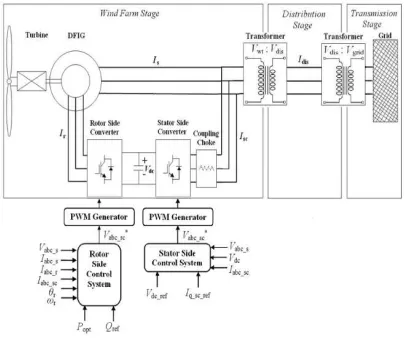
wind turbine through the pitch angle and generates the reference value of the rotor speed of the DFIG based on the measured wind speed and the reference value for active power tuned by Transmition System’ Operator (TSO) [25]. The DFIG control part, including the rotor side converter and grid side converter controllers, and the voltage regulator for the DC-link control the active and reactive power of the DFIG using the PI controllers.
Figure 1. DFIG based WT
2.1. DFIG Dynamic model
The voltage equations specified in a DFIG in the synchronous reference frame is presented as /
/ ( )
s s s s e s
r r r r e r r
u R i d dt j
u R i d dt j
(1)
By simplifying the voltage equationsdescribed above, the flux equations can be shown as
/
/ ( )
s s s s e s
r r r r e r r
d dt u R i j
d dt u R i j
(2)
In order to investigate the behavior of the DFIG the flux and current equations of the stator and the rotor must be used. Therefore, the transient flux relations are extracted and expressed in terms of current as:
( . . . ) ( . . . )
r m
s s r
ls lr ls m lr m ls lr ls m lr m
L L
i
L L L L L L L L L L L L
(3)
( . . . ) ( . . . )
s m
r s r
ls lr ls m lr m ls lr ls m lr m
L L
i
L L L L L L L L L L L L
(4)
/
( . . . ) ( . . . )
/ ( )
( . . . ) ( . . . )
r m
s s s s r e s
ls lr ls m lr m ls lr ls m lr m
s m
r r r s r e r r
ls lr ls m lr m ls lr ls m lr m
L L
d dt u R j
L L L L L L L L L L L L
L L
d dt u R j
L L L L L L L L L L L L
(5)
Finally, the space state equations of the DFIG in the synchronous reference can be expressed as:
/ ( . . . ) ( . . . ) / ( . . . ) ( . . . ) / ( . r m
sd sd s sd rd e sq
ls lr ls m lr m ls lr ls m lr m
r m
sq sq s sq rq e sd
ls lr ls m lr m ls lr ls m lr m
m
rd rd r
ls lr l
L L
d dt u R j
L L L L L L L L L L L L
L L
d dt u R j
L L L L L L L L L L L L
L
d dt u R
L L L
. . ) ( . . . ) ( ) / ( ) ( . . . ) ( . . . ) s
sd rd e r rq
s m lr m ls lr ls m lr m
s m
rq rq r sq rq e r rd
ls lr ls m lr m ls lr ls m lr m
L j
L L L L L L L L L
L L
d dt u R j
L L L L L L L L L L L L
(6)
2.2. Symmetrical voltage dip
When the voltage of the PCC drops due to a voltage sag in a faulted network, the induced motive force in the rotor frame is derived by the following equation
1
( ) /
(1 ) V g( )
L j t j t t
r m e r s r s
EMFr sVs g e j re e
Ls j e s
(7)
Regardless of
1/
s
, Eq. 7 can be presented as( ) /
(1 ) (1 )
L j t j t t
r m e r r s
EMFr sVs g e V gs s e e
Ls
(8)
From Eq. 8, it can be seen that the induction EMF amplitude is relatively large in the initial moment of the fault due to the DC offset in the flux. For example, if s = -0.2 and g=1, the amplitude of the EMF is 1.2V Ls m /Ls in the initial moments, which is 6 times the normal value. Fig. 2 shows
the induced EMF variation in the rotor due to changes in the stator flux.
Figure 2. The inducted EMF fluctuations in the rotor due to fluctuations in the stator flux.
3. The principle of PI control proposed method
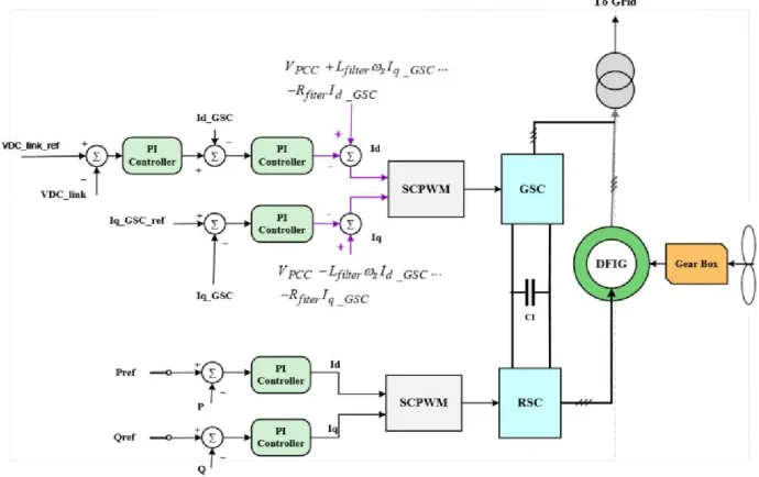
the DFIG has been controlled with six PI controller blocks including two blocks to control RSC, three blocks to control GSC, and one block to control rotor speed in turbine as shown as Fig. 3. There are various methods for tuning the controller parameters. In this paper, a test and error strategy has been used to design PI controllers’ parameters. Tuning and selecting the PI parameters is done in steady-state condition and transient behavior. Then, optimal PI parameters has been set in PI controller blocks in DFIG-based wind farm.
Figure 3. The proposed control method DFIG-based wind farm connected to infinite bus
4. Results and Discussions
This study has used the DFIG-based wind farm connected to the infinite bus for perusing the dynamic behaviour DFIG-based wind farm when the voltage sag occurs in the terminals of DFIG connected to the grid. The single line diagram of the test system is shown in Fig. 4. The model has been simulated in MATLAB/SIMULINK software. The parameters of the DFIG based WT are listed in Appendix.
Figure 4. The single line diagram of the test System
4.1. Fault
Three-phase fault has been occurred in the grid and the three-phase fault can be causes the voltage dip in the terminals of the DFIG. Values of voltage dip is 0.2 per unit and it takes 300 milliseconds and occurs in t = 5s. 650ms lasts until voltage is recovered to 1 per unit smoothly.
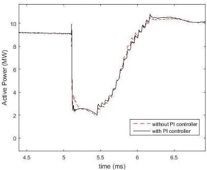
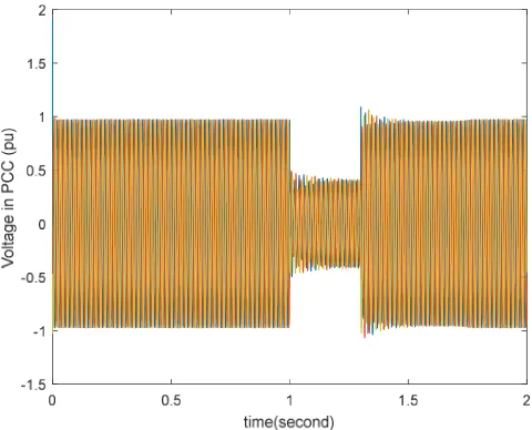
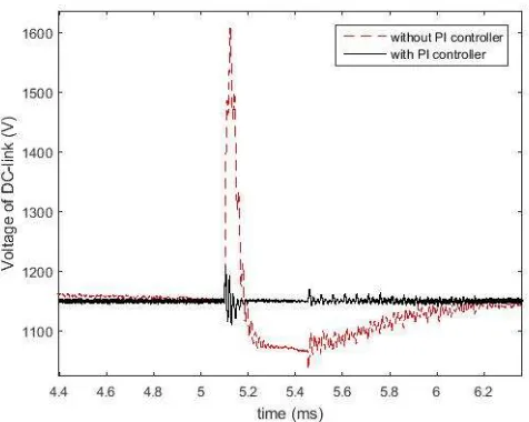
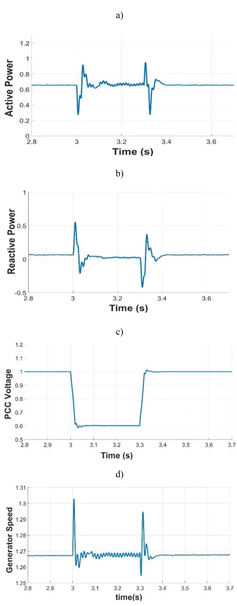
The results of the simulation have been prepared with and without PI controller for the rotor side converter and the PI controller for the voltage of the DC-link (regulator). In Fig. 5 can be seen the DC-link voltage with and without the PI controller. As curves present when the PI controller controls the RSC, the voltage of DC-link reduces. Fig. 6 presents the active power with and without PI controller in rotor side converter. As seen with omitted the PI Controllers in the RSC, active power is tuned and is not deference because there is the PI controller in the Grid side Converter and it is controls it. Fig. 7 presents the reactive power with and without the PI controller in the RSC. As seen in Fig 8, even though the PI controller has been eliminated, the reactive power is tuned because there is the PI controller in GSC. Fig. 8 also presents the voltage of the Common Coupling Point (PCC). In this figure used the PI controllers in the RSC and the GSC.
Figure 5. The DC-link voltage between the back-to-back converters
Figure 7. The reactive power that DFIG based WT generates
Figure 8. The voltage of the PCC in the DFIG-based wind farm
Figure 9. The voltage of the DC-link with and without the PI controller in the RSC and the GSC.
Figure 11. The reactive power with and without the PI controller in the RSC and the GSC
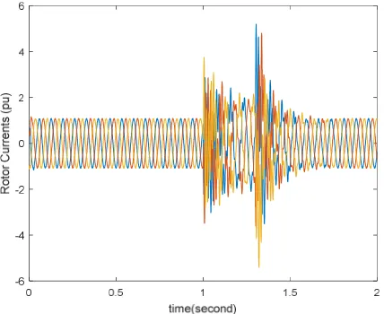
Figure 12. The rotor currents with the PI controllers when the fault happened 4.3. Result of tuning of PI parameters
In t3ms , a three-phase symmetric fault occurs in the network. The fault duration is 300 milliseconds and it causes a drop of 40% at the generator terminal.
a)
b)
c)
d)
a)
b)
c)
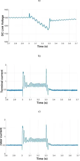
Figure 14. A voltage sag in t = 3s to t = 3.3s a) DC-link voltage, b) generator terminal current, c) rotor current.
5. Conclusions
or not tuned PI controllers, all of variables of the DFIG are varied. The tuned PI controllers can control The DFIG in a normal condition and steady state condition But they can’t control the DFIG-based wind farm for LVRT enhancement. faults are happened. In addition, it has been used the linear model of the DFIG-based wind farm and the effect of saturation has not been considered. The effect of saturation is one of the uncertainty. Therefore, the effect of saturation and nonlinear model of DFIG-based wind farm must be considered, then controllers for DFIG are designed and tuned.
Appendix A
DFIG Parameters
Rated power DFIG = 1.5 MW.
Stator voltage = 575 V.
Magnetization inductance generator= 2.9 pu.
Stator leakage inductance = 0.18 pu.
Rotor leakage inductance = 0.16 pu.
Rotor resistance = 0.016 pu.
Stator resistance = 0.023 pu.
Number of pair of poles = 3.
Conversion ratio from stator to rotor: 575/1975.
frequency = 60 Hz.
H = 0.658.
Symbols and abbreviations B
s
L Stator Inductance P Number of paired machine poles
r
L Rotor Inductance Tm Mechanical torque
lr
L Rotor leakage inductance Tsh Input torque from axis to generator
ls
L Stator leakage inductance Ht Fixed inertia turbine
m
L Mutual inductance
b Based velocitys
i Stator current vector t Torsion angle shaft
r
i Rotor current vector
Air densitys
u Stator voltage vector R Turbine Radius
r
u
Rotor voltage vector Pitch angles
R Stator resistance
Wind speedr
R Rotor resistance CP Power factor
e
Synchronous angular velocity Vs Stator Voltage magnitude
r
Rotor angular velocity
ss
Stator Flux in the Stator Reference Frame
s e r
Slip angular velocity Cdc DC link capacitor
rm
Mechanical rotor rotation velocity ios Grid side converter current
r s
r r
EMF Induced electrical motive force in the rotor in the reference frame of the rotor idL The current flows from the network to the grid side convertor
Coupling coefficient m Modulation coefficient
s
Stator time constant g Percentage of voltage drop.
s Induction machine slip V1 Positive sequence stator voltage p Number of machine poles V2 Negative sequence stator voltage
sn
stator natural flux thershhold maximum stator natural flux
dc
U DC-link voltage
References
1. 1. Dong, H.; Wu, H.; Pan, J.; Chen, Y.; Xu, B. Research on Double-Fed Induction Generator Low Voltage Ride Through Based on Double Braking Resistors Using Fuzzy Control. Energies 2018, 11, 1155, doi:10.3390/en11051155.
2. 2. Tohidi, S.; Behnam, M. A comprehensive review of low voltage ride through of doubly fed induction wind generators. Renew. Sustain. Energy Rev. 2016, 57, 412–419, doi:10.1016/J.RSER.2015.12.155.
3. 3. Shen, Y.; Cui, M.; Wang, Q.; Shen, F.; Zhang, B.; Liang, L. Comprehensive Reactive Power Support of DFIG Adapted to Different Depth of Voltage Sags. Energies 2017, 10, 808, doi:10.3390/en10060808. 4. 4. Zheng, Z.; Yang, G.; Geng, H. Coordinated Control of a Doubly-Fed Induction Generator-Based Wind
Farm and a Static Synchronous Compensator for Low Voltage Ride-through Grid Code Compliance during Asymmetrical Grid Faults. Energies 2013, 6, 4660–4681, doi:10.3390/en6094660.
5. 5. Sørensen, P.; Hansen, A. D.; Christensen, P.; Meritz, M.; Bech, J.; Bak-Jensen, B.; Nielsen, H.; Risø National Lab., R. (DK). W. E. D. Simulation and verification of transient events in large wind power installations.; 2003; ISBN 8755030300.
6. 6. Zhou, X.; Tang, Y.; Shi, J. Enhancing LVRT Capability of DFIG-Based Wind Turbine Systems with SMES Series in the Rotor Side. Int. J. Rotating Mach. 2017, 2017, 1–8, doi:10.1155/2017/4635452.
7. 7. Abuhussein, A.; Ali, M. H. International journal of renewable energy research IJRER.; Gazi Univ., Fac. of Technology, Dep. of Electrical et Electronics Eng, 2014; Vol. 4;.
8. 8. Pannell, G.; Zahawi, B.; Atkinson, D. J.; Missailidis, P. Evaluation of the Performance of a DC-Link Brake Chopper as a DFIG Low-Voltage Fault-Ride-Through Device. IEEE Trans. Energy Convers. 2013, 28, 535–542, doi:10.1109/TEC.2013.2261301.
9. 9. Jin Yang; Fletcher, J. E.; O’Reilly, J. A Series-Dynamic-Resistor-Based Converter Protection Scheme for Doubly-Fed Induction Generator During Various Fault Conditions. IEEE Trans. Energy Convers. 2010, 25, 422–432, doi:10.1109/TEC.2009.2037970.
10. 10. Abed, N. Y.; Kabsha, M. M.; Abdlsalam, G. M. Low Voltage Ride-Through protection techniques for DFIG wind generator. In 2013 IEEE Power & Energy Society General Meeting; IEEE, 2013; pp. 1–6. 11. 11. Yang, L.; Xu, Z.; Ostergaard, J.; Dong, Z. Y.; Wong, K. P. Advanced Control Strategy of DFIG Wind
Turbines for Power System Fault Ride Through. IEEE Trans. Power Syst. 2012, 27, 713–722, doi:10.1109/TPWRS.2011.2174387.
12. 12. Khamaira, M. Y.; Shiddiq Yunus, A. M.; Abu-Siada, A. Improvement of DFIG-based WECS performance using SMES unit. In 2013 Australasian Universities Power Engineering Conference (AUPEC); IEEE, 2013; pp. 1–5.
13. 13. Wang, B.; Qian, Y.; Zhang, Y. Robust nonlinear controller design of wind turbine with doubly fed induction generator by using Hamiltonian energy approach. J. Control Theory Appl. 2013, 11, 282–287, doi:10.1007/s11768-013-1116-0.
14. 14. Iyasere, E.; Salah, M. H.; Dawson, D. M.; Wagner, J. R.; Tatlicioglu, E. Robust nonlinear control strategy to maximize energy capture in a variable speed wind turbine with an internal induction generator. J. Control Theory Appl. 2012, 10, 184–194, doi:10.1007/s11768-012-0315-4.
16. 16. Van, T. L.; Ngyen, T. D.; Tran, T. T.; Nguyen, H. D. Advanced Control Strategy of Back-to-Back PWM Converters in PMSG Wind Power System. Adv. Electr. Electron. Eng. 2015, 13, 81–95, doi:10.15598/aeee.v13i2.1161.
17. 17. Gayen, P. K.; Chatterjee, D.; Goswami, S. K. An improved low-voltage ride-through performance of DFIG based wind plant using stator dynamic composite fault current limiter. ISA Trans. 2016, 62, 333–348, doi:10.1016/J.ISATRA.2016.01.023.
18. 18. Rahim, A. H. M. A.; Nowicki, E. P. Supercapacitor energy storage system for fault ride-through of a DFIG wind generation system. Energy Convers. Manag. 2012, 59, 96–102, doi:10.1016/J.ENCONMAN.2012.03.003.
19. 19. Zhang, X.; Cao, X.; Wang, W.; Yun, C. Fault Ride-Through Study of Wind Turbines. J. Power Energy Eng. 2013, 1, 25–29, doi:10.4236/jpee.2013.15004.
20. 20. Oliveira, F.; Amorim, A.; Encarnação, L.; Fardin, J.; Orlando, M.; Silva, S.; Simonetti, D. Enhancing LVRT of DFIG by Using a Superconducting Current Limiter on Rotor Circuit. Energies 2015, 9, 16, doi:10.3390/en9010016.
21. 21. Ibrahim, A. O.; Nguyen, T. H.; Lee, D.-C.; Kim, S.-C. A Fault Ride-Through Technique of DFIG Wind Turbine Systems Using Dynamic Voltage Restorers. IEEE Trans. Energy Convers. 2011, 26, 871–882, doi:10.1109/TEC.2011.2158102.
22. 22. Naderi, S. B.; Negnevitsky, M.; Jalilian, A.; Tarafdar Hagh, M.; Muttaqi, K. M. Low voltage ride-through enhancement of DFIG-based wind turbine using DC link switchable resistive type fault current limiter. Int. J. Electr. Power Energy Syst. 2017, 86, 104–119, doi:10.1016/J.IJEPES.2016.10.001.
23. 23. Swain, S.; Ray, P. K. Short circuit fault analysis in a grid connected DFIG based wind energy system with active crowbar protection circuit for ridethrough capability and power quality improvement. Int. J. Electr. Power Energy Syst. 2017, 84, 64–75, doi:10.1016/J.IJEPES.2016.05.006.
24. 24. Vo Tien, D.; Gono, R.; Leonowicz, Z.; Tran Duy, T.; Martirano, L. Advanced Control of the Dynamic Voltage Restorer for Mitigating Voltage Sags in Power Systems. Adv. Electr. Electron. Eng. 2018, 16, 36–45, doi:10.15598/aeee.v16i1.2350.