1811
A VLSI Structure For Computing Of 2D
DCT Image Straining
Prashant Chaturvedi, Dr. Soni Changlani
Abstract: Statistics photograph straining is the deficiency of redundancy in statistics illustration so one can obtain discount in storage value. DCT is broadly used in picture and video compression system. Some of algorithms had been proposed for implementation of DCT. Right here in this paper we review on 2D-DCT architecture by the use of 2D-DCT separability belongings by the use of a transpose buffer and also put into effect of optimization as well Zigzag parallel pipeline using VHDL. It was also discussed the VHDL synthesis results uses 615 slices, seventy four i/o pins, 6 multiplier,5651 logic mobile, operating frequency 124 MHz and pipeline latency one hundred sixty clock cycle. The coding is spurious the use of Xilinx 9.2i ISE synthesizedi
the usage of Spartan 3E XC3S500.
Keywords: JPEG, DCTi, Ycbcr, FIFO, Quantization, Zig-Zag, FPGA Spartran-3E.
————————————————————
1.
INTRODUCTION
Mainframe photographs applications, in particular those generative virtual snap shots and another sophisticated color pics, can procreate very huge report shape. Troubles of depot area also this necessity the swiftly transport photograph record throughout systems also by the net, have consequently induced the flourish for a variety of photo straining strategies, to takeoff the hylic duration for documents.[2]Thei maximum not unusual shape of photo compression is called JPEG. JPEG professional group inside the past due 1980’s evolved this trendy. Thei board foremost widespread changed into entitled as standard JPEGi. At 1996’s, JPEGi board commenced to research probability for brand recent picture straining. Popular which could serve extant & subsequent packages.[21] Thei JPEGi structure and VHDL format of a two D DCT by quantizationi & zig-zag order. This structure is used due to the fact the center and route in JPEGi illustration straining hardwarei. The two D DCT computation is made the use of the two D DCT echeloned property, such that the complete construction is split into 2 one D DCT enumeration through the usage of a transposei buffer. Shape for quantizationi& zig-zag way is also defined in these documents. Thei quantizationi technique is finished using distribution manipulation. [3] DCT along by programs in audio Penetrate to video Straining on numerical resources that alters the data at the time or territory wing names by the frequencyi area, similar a well known other gear and also communication expression may be move or used greater effectively to attain utility desires. The JPEG compression doctrine is using controllable impairment into attain advanced straining charges. On this reference the data is converted to be frequency vicinity via dct. Due to fact that vicinal picture element in an photograph have high probability of display succinct
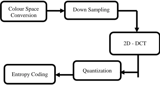
version in dye, the DCT out-turn will organization the better amplitudes within the decrease endemic frequencies. [15] The JPEG straining can be split into 5 vital steps, colour place modification down samplingi, 2D-DCT, Quantizationi & Entropyi coding. Thei primary manipulations are used best for dye snap shots. The dye place modification lection the RGB entry photograph to a luminancei and chrominancei stead shade, which include the Ycbcr illustration. Thei down samplingi procedure alleviate the samplingi fee of the colour facts cb & cr forasmuch of the fact the chrominancei additives are sparing vital to the human glimmers. The quantizationi procedure renounces the 2D- DCT excessive frequency also minor amplitudei co-efficients. Thei JPEGi Straining is a lossy Straining, due to the facts down sampling and quantization operations are irreversible. [16]
Fig 1: JPEG Straining Steps for Colour Picture
Already stated that documents in limelight handiest among a pipelined hardware execution for the principle segment of the JPEG norm the 2D DCT. Essential modulei to be designedi into JPEGi compressor hardware due to its excessive algorithmi subtlety. These paintings introduce to begin with a FPGAi execution for suppleness, term-to-end also growth feature. Thei effects from RTL degree VHDL layout can be reused for an ASICi execution within forthcoming and the design VHDLi for two D DCT computation can be used as a center into different picture like program straining. [1]
Colour Space Conversion
Down Sampling
2D - DCT
Quantization Entropy Coding
______________________________
Prashant Chaturvedi P.hD Scholor in Electronics & Communication Engineering ( VLSI ) at L.N.C.T University Bhopal, India Ph.No- 8109528276, E-mail: [email protected] Dr. Soni Changlani Professor in Department of Electronics &
1812
2.
PROPOSED WORK
JPEG encoder center is meant to be encoded raw bitmapped pix into JPEGi compliant for encipher bite flow. JPEGi standard encodingi technique is used. The structure is given in discern 1, widespread device architecture includes encoding chain commenced out of amphitryon programming interfaces figure 1. The architecture is given in figure 2. Host records interfacei shall constantly scribe BUF_FIFOi so long as FIFOi approximate complete sign is obtained. Then, it needs to prevent also await sign FIFOi approximate full to deassert. While that is the regard must retain writing and so forth. Encodingi is governed through controlleri and is a pipelined technique where every pipage degree procedure 16▪8 blocks of pattern upon a period.16▪ 8 blocks is known as ―information unit‖.
Data (23:0).
O/P Fig 2: Proposed JPEG Encoder Core Architecture
Following steps are accomplished: line buffering, chroma sub sampling RGB to Ycbcr changeover [12], discrete cosine Transform 2-dimensional [9] [10], followed with the aid of Zigzag take a look at including quantization. The 2D-DCT is to be computation has an excessive diploma of computational complexity. For the reason that many authors have proposed simplifications to this computation, as [15] [16] [17] and others, this complexityi may be decrease consistent with the application exigency. Especially in order to photograph compression packages there are numerous design to count the 2D-DCT factor & the design selected in this paper changed into introduced and changed in.[18]
3.
PROPOSED FPGA
I
IMPLEMENTING OF
JPEG
I
STRAINING
A. BUF_FIFO
Hosti statistics interface compose enter photo list through queue the BUF_FIFOi. This FIFOi is supposed that reduce delay among uncooked picture loading & encodingi inception. Its plays rasterization to dam modification line wise enter to 8▪8 block conversion. BUF_FIFOi is sincerely a fixed storage. BUF_FIFO need to be capable of keep upon the minimal eight strains by enter picture, in order that JPEGi encoding may be initiate out in order to
8▪8 segment. Fixed storage shape is
configurable thru VHDLi from eight to sixteen strains with one line steps.16 strains BUFFERi allow maximum pace at the same time as eight strains gives lowest vicinity. This is shown in figure 3
Img Wdth Data
of
Fifo Hlf Full
Fig 3: Proposed BUFFIFO Architecture
FDCTi is meant to carry out features: RGB to ycbcr modification chroma sub sampling, enter degree shift and dct.
Under mentioned, equalization is implemented by means of multipliers and adders to perform conversion:
y = (0.299 ▪ r) + (0.587 ▪ g) + (0.114 ▪ b)...(i)
cb = (-0.1687 ▪ r) - (0.3313 ▪g) + (0.5 ▪ b)+128...(ii)
cr = (0.5 ▪ r) - (0.4187 ▪ g) - (0.0813 ▪ b)+12...(iii)
Stagnant used on present naturalization is layout fourteen bits of exactitude indication one sign bit on MSB. That is shown in discern 4
HOST DATA
BUF FIFO
R G B TO Ycbcr
2D-DCT
Zig-Zag
QUANTIZER PIPELINE CONTROLLER
HOST PROG
HOSTIF
CTRL SM
HOST DATA
COTROLLER
HALF FULL GEN
BLK READ CTRL
SUB RAM
1813
Empty
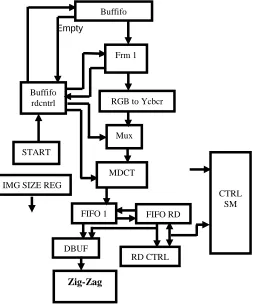
Fig 4: Proposed FDCT Architecture B. DCT
Fig 5: 2D-DCT Architecture
The 2D-DCT 8▪8 DCT is carried out via the row column decompositioni technique. Firstly reckon the one-D DCT i.e. +8 ▪ 1 DCT of every columni by the input facts matrixi x to yielding XtC. subsequently suitable rounding, or truncate, the transposei of the ensuing matrixi, XtC is saved in transpose buffer. After that reckon few other one-D DCT i.e. 8 ▪ 1 DCT of every row of CtX to yielding the favored two–D DCT as described in equalization (i). A segment sketch for the layout is shown in fig 5.Two-D DCT center blended by strata shift. operation upon segment of sixty four samples. Receive eight bit entry & produced 12 bit output .Heretofore uncoded photograph is strata shifted from unsignedii whole numbers by variety. [0, 2^Q - 1] to signedi whole numbers by extent [-2^ (Q-1), 2^ (Q-1)-1]. X^Q way here x to strength of Q.Now two-D-DCT is executed the usage of under mentioned, equalization:
Cp,q = √2/m cos [(2r-1)(s-1)π/2m………..…….(iv)
For i = 1, 2… m, j = 2, 3… m, and Ci,j = m -1/2 for s = 1.
MDCTi takes statistics row-wisei however outputs column-wisei. Then find out line-sensible behest its miles essential by transposei output DCT matrixi .FIFOi 1 is vicinity for five 8▪8 segment DCT consequences. Then length = 5▪64▪12 bit. FIFOi examine curb has inner slug FIFO_CNTi (6:0) to depend amount of sentences have a look at in line with one BEGINNING_PB then BEGINNING_PB justify. Twin port fixed storage 2▪64▪12bit.Twofold bufferi essential in order to pipeline Buf_sel signal is used like MSB into examine deal with by dbuf. ~buf_sel inverse is used like MSB by inscribe deal with by dbufi. [1]
C. Zig_Zag
Zig-Zag block is to carry out so referred to as zig_zag check. Its miles absolutely reorder of samples positions in a single 8▪ 8 block in keeping with under cited tables.
Table I: Zig-Zag Process
0 1 2 3 4 5 6 7
8 9 10 11 12 13 14 15
16 17 18 19 20 ... ...
... ... 62 63
0 1 5 6 14 15 27 28
2 4 7 13 16 26 29 42
3 8 12 17 25 30 41 43
9 11 18 24 31 40 44 53
10 19 23 32 39 45 52 54
20 22 33 38 46 51 55 60
21 34 37 47 50 56 59 61
35 36 48 49 57 58 62 63
It approaches as an instance that I sample position zero is design then equal output place zero . Sample II is design to output place V.
Thei structure of Zig-Zag is shown in discern 6 below
(e)
Fig 6: Proposed Zig-Zag Architecture
Buffifo
Frm 1
Buffifo
rdcntrl RGB to Ycbcr
Mux
MDCT
FIFO 1 FIFO RD
DBUF
RD CTRL
Zig-Zag
CTRL SM START
IMG SIZE REG
1D-DCT (8 ▪ 1)
Transpose Buffer 1D-DCT (8 ▪ 1)
DCT
RDCTRL ZIGZAG FIFO CTRL
CTRL SM
FF
WRCTR
CTRL SM NOT
1814 Zig-Zag center is acting records for of input sample
rconsistent with The Zig_Zag collection. So that reason reorderi fixed storage is usedi. Now fixed storage need to happen packeded by under mentioned values inscribed to deal with zero to cope with 63.
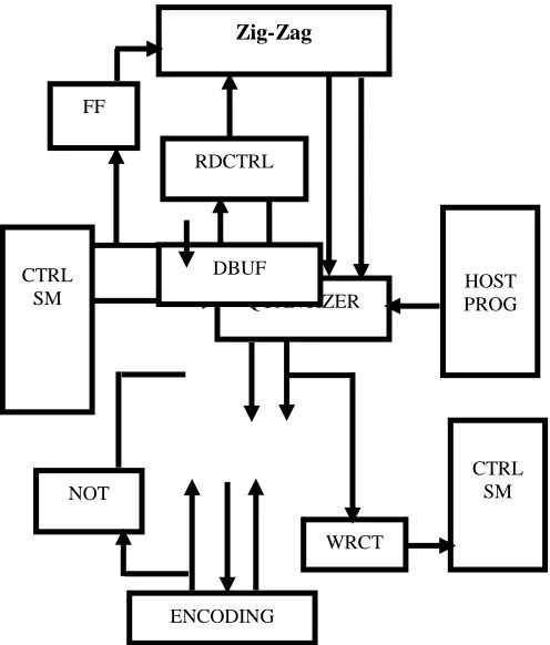
D. QUANTIZER
Quantizer accomplishes split of enter samples by way of described quantization values. Works pattern smart. Host can fill in sixty four special quantization coefficients to inner ram (64▪8 bits)
Under mentioned, equalization is implemented:
foutput (a, b) = ROUND (finput (a, b)/q (a, b)…………. (5) a, b –Rectangular Coordinates
finput – entry sampler to quantizeri foutput – Output sampler from Quantizeri. Rounding to nearest integer
It is Quantizeri modules includes fixed storage also divideri. Those quantizing valuation are heretofore saved in fixed storage. The divider contains out department in a pipelined way. The first DCT coefficient popping out from 2-D 2-DCT module is split by the primary cost from the quantization desk this is already saved in fixed storage, also two-DCT Co-efficient is split with the 2 measure by the list, as overall sixty four Co-efficient are split via the measure in quantizationi desk.[3
Fig 7: Proposed QUANTIZER Architecture
4.
RESULTS
The 2D-DCT, Quantization & Zig-Zag Structure tuned in to define in VHDL. This VHDL become synthesize right in to a Xilinx Spartan 3E own familyi FPGA [14].Thei Whole synthesis consequences to Spartan 3Ei FPGA are supplied in desk 2, whose hardwarei became suitable in an XCS5000E tool. Thei list 3 extant the evaluation between [3] and the existing work on this research.
Table II: Device utilization the use of Xilinx spartran-3E for general architecture proposed in this research
Logic Units Used Available Utilization
Number of slices 1663 4656 36%
Number of 4 input
LUTs 2044 9312 22%
Number of Bonded
IOBs 37 231 16%
Number of multipliers 18x18
8 20 40%
Number of slices
FFs 1907 9312 20%
Table III: current article Two D DCT end consequence is as juxtapose with paintings of Two-D DCT layout of [III].
Logic Units Proposed[1] Previous[3]
Number of slices 615 1891
Number of 4 input look up
table look up table 437 1671
Number of Bonded
input output blocks 74 51
Number of multipliers
18 ▪ 18 6 8
Number of slices FFs 975 2450
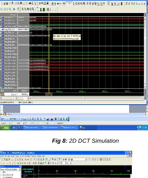
According in the line with synthesis end results, maximum time put off offered is 8.861 ns. That duress yields minimal horologe length 8.006 ns. Most horologe frequency may be usedi is 124.09 MHz. Most lateness, synthesizedi is an awful lost minor than postpone offered to one-D DCT formation in yields maximum time postpone 76.03ns. Gadget in A. Shams et al. [1] uses absolutely parallel processing without horologe for reckons eight points one-D DCT. The gadget is used to assessment context as it makes use of identical FPGA with this machine. For the reason that system T. Pradeepthi et al. [3] uses heading FPGAi forasmuch is better frequencyi than Spartani of postpone is a good deal minor upto machine also most frequency is highest. Discem beneath demonstrate the output consequence the exceptional degrees.
Zig-Zag
FF
RDCTRL
HOST PROG QUANTIZER
CTRL SM
CTRL SM
ENCODING
WRCT NOT
1815 Fig 8: 2D DCT Simulation
Fig 9: Zigzag Simulation Result
Fig 10: Quantization Simulation Result
Comparative Results
Fig 11: Comparative Results Device utilization for total architecture and proposed work for table II.
Fig 12: Comparative Results 2-D DCT is proposed work and previous work for table III.
5.
CONCLUSION
JPEG center programming tuned in to finished via host interference using Xilinx micro blaze processor 32 bit aligned accesses are supported with in proposed approach as a results enter deal with should be more than one of 4. All sign in are 32 bit big line buffering, chrome sub sampling, RGB to Ycbcr conversion, 2D-DCT followed wid the resource of Zig-Zag scan, quantizer has been carried out look at the strolling of proposed method. Comparative analysis of proposed approach with the previous one proven in table II and table III.
REFERENCES
[1] Prashant Chaturvedi, Prof. Tarun Verma and Dr. Rita Jain ―FPGA Implementation of 2-D DCT Architecture for JPEG Image Compression‖, International Journal of Advanced Electronics & Communication Systems, CSIR-NISCAIR ISSN No: 2277-7318, Issue 3 Vol 1, Jan 2013 Paper ID 11263. [2] Prashant Chaturvedi, Prof. Tarun Verma and Prof. M.
Zahid Alam, ―A Novel VLSI based Architecture for Computation of 2D-DCT Image Compression‖, International Journal of Electrical, Electronics and
0 2000 4000 6000 8000 10000
Used
Available
Utinization
0 500 1000 1500 2000 2500
Proposed [1]
1816 Computer Engineering 1(2): (IJEECE) (2277-2626).
65-70 Dec 2012 Vol 2, Issue 2, pp 65-65-70 Dec 2012.
[3] T.Pradeepthi1 and Addanki Purna Ramesh ―Pipelined Architecture of 2D-DCT, Quantization and Zigzag Process for Jpeg Image Compression using VHDL‖ International Journal of VLSI design & Communication Systems (VLSICS) Vol.2, No.3, September 2011 . [4] ATAKAN DOĞAN, İSMAIL SAN ―A LOW AREA FULLY
PIPELINED IMPLEMENTATION OF JPEG ON FPFA‖ ESKISHIR TECHINICAL UNIVERSITY JOURNAL OF SCIENCE & TECHNOLOGY. 19(3), PP. 685 - 697, 2018.
[5]C. SCAVONGELLI* AND M. CONTI ―FPGA IMPLEMENTATION OF JPEG ENCODER ARCHITECTURES FOR WIRELESS NETWORKS‖, SCAVONGELLII AND CONTI EURASIP JOURNALI ON EMBEDDED SYSTEMS, SPRINGER OPEN, 2017, PP 1-19. [6 ]MEERA NEGI, RUCHI SHARMA ―IMAGE COMPRESSION
ALGORITHMS USING VHDL TECHNIQUES‖, INTERNATIONAL JOURNAL OF ENGINEERING RESEARCH & TECHNOLOGY, ISSN: 2278-0181, SPECIAL ISSUE – 2017, PP 1-13.
[7] WADHAH AYADI, WAIDI ELHAMZI, MOHAMED ATRI ―A FPGA-BASED IMPLEMENTATION OF JPEG ENCODER‖, INTERNATIONAL IMAGE PROCESSING IEEE CONFERENCE, 2016.
[8] MR. AMIT D. LANDGE, MR. S.A. BAGAL, MR. S. M LICHADE ―GRAYSCALE IMAGE COMPRESSION USING DISCRETE COSINETRANSFORM‖,IJEDRI| VOLUME 4, ISSUE 2 | ISSN: 2321-9939, 2016 PP1-8.
[9] Trang T.T., Binh P. Nguyen ―A Accuracy and High-Speed 2-D 8x8 Discrete Cosine Transform Design‖. Proceedingsi of ICGCRCICT 2010, vol. 1, 2010, pp. 135-138.
[10] Xilinx, Inc., ―2D Discrete Cosine Transform (DCT) V2.0 ‖,
Logicore Product Specification, Xilinx Corporation, 2002.
[11] A. Shams, A. Chidanandan, W. Pan, and M. Bayoumi, ‖NEDA: A
low power high throughput DCT architecture‖, IEEE Transactions
on Signal Processing, vol.54(3), Mar. 2006.
[12] The International Telegraph and Telephone Consultative Committee (CCITT). ―Information Technology – Digital Compression and Coding of Continuous-Tone Still Images – Requirements and Guidelines‖. Rec. T.81, 1992.
[13] W. Pennebaker, J. Mitchell. JPEG Still Image Data Compression Standard, Van Nostrand Reinhold, USA, 1992.
[14] ―Home site of the JPEG and JBIG committees‖, <http://www.jpeg.org/> (21/04/01)
[15] V. Bhaskaran, K. Konstantinides.,‖ Image and Video Compression Standards Algorithms and Architectures – Second Edition‖, Kluwer Academic Publishers, USA, 1999.
[16] I. Basri, B. Sutopo, ―Implementation 1D-DCT Algoritma Feig- Wino grad di FPGA Spartan-3E (Indonesian)‖. Proceedings of CITEE 2009, vol. 1, 2009, pp. 198-203 [17] J. Miano. Compressed Image File Formats – JPEG,
PNG, GIF, XBM, BMP, Addison Wesley Longman Inc, USA, 1999.
[18] B.G. Lee, ― A new algorithm to compute the discrete cosine transform‖ ―IEEE Trans. Acoust., Speech,
Signal Processing, vol. ASSP-32, pp. 1243-1245, Dect.1984.
[19] H.S Hou, ―A fast recursive algorithms for computing the discrete cosine transform, ―IEEE Trans. Acoust., Speech, Signal Processing, vol. ASSP-35, pp. 1455-1461, Oct.1987.
[20] N.I Cho and S.U.Lee, ―DCT algorithms for VLSI parallel implementation,―IEEE Trans. Acoust., Speech, Signal Processing, vol 38. pp. 121-127, Jan.1990. [21]. W. Pennebaker, J. Mitchell. JPEG Still Image Data Compression
Standard, Van Nostrand Reinhold, USA, 1992. [22]. A. Shams, A. Chidanandan, W. Pan, and M. Bayoumi, ‖NEDA: A
Signal Processing, vol.54(3), Mar. 2006.
[23]. B.G. Lee, ― A new algorithm to compute the discrete cosine ]
transform‖ ―IEEE Trans. Acoustic., Speech, Signal Processing, vol
ASSp-32 pp 1243- 1245 Dec-1984.
[24]. H.S Hou, ―A fast recursive algorithms for discrete cosine
transform, ―IEEE Trans. Acoust., Speech signal processing vol,
ASSP- 35,pp 1455-1461 oct 1987
[25]. J. Miano. Compressed Image File Formats – JPEG, PNG, GIF, XBM, BMP, Addison Wesley Longman Inc, USA, 1999.
[23]. N.I Cho and S.U.Lee, ―DCT algorithms for VLSI parallel implementation, ―IEEE Trans. Acoust., Speech, Signal Processing,