2872
Renewable Energy Source Integration With
Linear And Nonlinear Control Techniques
Sivaraman P, Sakthi Suriya Raj J S, Prem P, Matheswaran AAbstract—Energy harvesting from a renewable resource is most challenging and complex issue of the industry whether it is the electric utilities or for industrial applications. Multiport dc/dc converters can combine the different types of dc voltage sources with different V-I characteristics in input side and generate different levels of dc voltages at the output side. The main aim of using the converters and battery energy storage (BES) system is to reducing the cost, number of power electronic components and frequency control, increasing the reliability and efficiency of the overall system. Therefore, new and evolving applications are growing in the areas of electric and electric hybrid vehicles, portable electronics and storage of electric energy produced by renewables like solar or wind generators. Here the performance of hybrid renewable energy integration system is simulated and analyzed by using the fuzzy logic controller and PID controller.
Index Terms—BES, BMS, Boost converter, Controller, Fuzzy, Renewable, PID.
—————————— ——————————
1 I
NTRODUCTION We all know that the world is facing a major threat of fast depletion of the fossil fuel reserves. Most of the present energy demand is met by fossil and nuclear power plants. A small part is met by renewable energy technologies such as wind, solar, biomass, geothermal, etc. There will soon be a time when we will face a severe fuel shortage. As per the law of conservation of energy, “Energy can neither be created, nor be destroyed, but it can only be converted from one form to another”. Most of the research is to conserve the energy and how to utilize the energy reliable. Among them, wind and solar power sources have experienced remarkably rapid growth in the past 10 years [1]. Both are pollution-free sources of abundant power. With high economic growth rates and over 17 percent of the world’s population, India is a significant consumer of energy resources.Solar energy is energy from the Sun. It is renewable, inexhaustible and environmental pollution-free. Solar charged battery systems provide power supply for complete 24 hours a day irrespective of bad weather. By adopting the appropriate technology, we can extract a large amount of power from solar radiations [2]. Moreover, solar energy is expected to be the most promising alternative source of energy.
Wind energy is the kinetic energy associated with the movement of atmospheric air. Wind energy systems convert this kinetic energy to more useful forms of power. Wind energy systems for irrigation, milling and used to generate electric power. Windmills for water pumping have been installed in many countries particularly in the rural areas. Wind turbines transform the energy in the wind into mechanical power, which can then be used directly converting to electric power to generate electricity. Wind turbines can be
used singly or in clusters called ’wind farms. There is a growing awareness that renewable energy such as photovoltaic system and Wind power have an important role to play in order to save the situation [3]. The hybrid power system consists of a combination of renewable energy sources such as wind generators, solar acts as a dual source [4] to charge batteries and provides power to meet the energy demand, considering the local geography and other details of the place of installation. These types of systems are not connected to the main utility grid. They are also used in stand-alone applications and operate independently and reliably [5]. The best application for these types of systems is in remote places, such as rural villages, in telecommunications, etc. The importance of hybrid systems has grown as they appear to be the right solution for clean and distributed energy production.
Aim of using boost converters is reducing the cost and number of power electronic components and increasing the reliability and efficiency of the overall system [6].
Power plants typically produce more power than necessary to ensure adequate power quality [7]. By taking advantage of energy storage within the grid, many of these inefficiencies can be removed. When using battery energy storage systems (BESS) for grid storage, advanced modeling is required to accurately monitor and control the storage system. A battery management system (BMS) controls how the storage system will be used and a BMS that utilizes advanced physics-based models will offer for much more robust operation of the storage system [8].
Measures of the performance of the different battery technologies used in a PV-battery system were obtained by the energy return factor and the overall battery efficiency. With a battery storage capacity three times higher than the daily energy output, the energy return factor for the PV- battery system ranged from 0.64 to 12 for the different cases. Some of the emerging technologies studied (e.g. Li-ion, NAS) exhibit performance suitable for use in PV- battery systems, resulting in higher energy return factors and overall battery efficiencies than for the established battery technologies [9].
————————————————
Sivaraman P, Bannari Amman Institute of technology, Sathyamanagalam, Erode, Tamil Nadu, India, E-mail: [email protected].
Sakthi Suriya Raj J S, Bannari Amman institute of technology, Sathyamanagalam, Erode, Tamil nadu, India, E-mail:
2873
2
R
ESEARCHM
ETHOD2.1 INTRODUCTION TO BOOST CONVERTER
A Boost converter is a switch-mode DC to DC converter in which the output voltage is greater than the input voltage. It is also called as Step Up Converter. The name step-up converter comes from the fact that analogous to step up transformer the input voltage is stepped up to a level greater than the input voltage. It is a class of switching-mode power supply (SMPS) containing at least two semiconductor switches (a diode and a transistor) and at least one energy storage element. Filters made of capacitors (sometimes in combination with inductors) are normally added to the output of the converter to reduce output voltage ripple [10], [11].
Figure 1. Block diagram of Renewable Energy source Integration Figure1 shows the block diagram of renewable energy source integration through the boost converter.
Fig. 2 Boost Converter Schematic 2.2
O
PERATINGP
RINCIPLEThe key principle that drives the boost converter is the tendency of an inductor to resist changes in current. When being charged it acts as a load and absorbs energy (like a resistor), when being discharged, it acts as an energy source (like a battery). The voltage it produces during the discharge phase is related to the rate of change of current, and not to the original charging voltage, thus allowing different input and
output voltages [12].
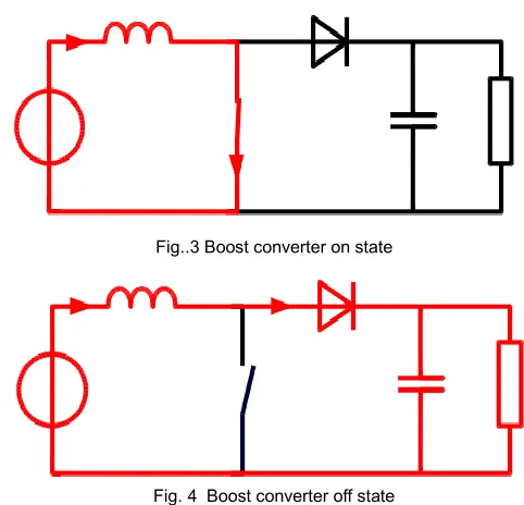
Fig..3 Boost converter on state
Fig. 4 Boost converter off state
The two configurations of a boost converter, depending on the state of the switch S. The basic principle of a Boost converter consists of 2 distinct states (Fig..3 and Fig..4)
• In On-state, the switch S (Fig. 3) is closed, resulting in an increase in the inductor current
• In Off-state, the switch is open and the only path offered to inductor current is through the flyback diode D, the capacitor C and the load R. This result in transferring the energy accumulated during the On-state into the capacitor. • The input current is the same as the inductor current as can be seen in Fig. 2. So, it is not discontinuous as in the buck converter and the requirements on the input filter are relaxed compared to a buck converter [14].
2.3 M
ODES OFO
PERATION OFB
OOSTC
ONVERTER The boost converter can be operated in two modesa) Continuous conduction mode in which the current through inductor never goes to zero i.e. inductor partially discharges before the start of the switching cycle.
b) Discontinuous conduction mode in which the current through inductor goes to zero i.e. inductor is completely discharged at the end of switching cycle.
2.4
C
IRCUITA
NALYSIS OFB
OOSTC
ONVERTER2.4.1 CONTINUOUS MODE
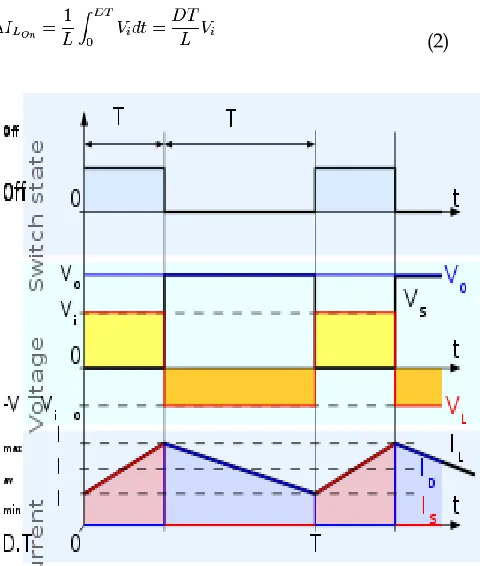
2874 (1)
At the end of the On-state, the increase of IL is therefore
(2)
Fig. 5. Waveforms of current and voltage in continuous mode D is the duty cycle. It represents the fraction of the commutation period T during which the switch is On. Therefore, D ranges between 0 (S is never on) and 1 (S is always on).
During the Off-state, the switch S is open, so the inductor current flows through the load. If we consider zero voltage drop in the diode, and a capacitor large enough for its voltage to remain constant, the evolution of IL is
(3)
Therefore, the variation of IL during the Off-period is
(4)
As we consider that the converter operates in steady-state conditions, the amount of energy stored in each of its components has to be the same at the beginning and at the end of a commutation cycle [16]. In particular, the energy stored in the inductor is given by
(5)
So, the inductor current has to be the same at the start and end of the commutation cycle. This means the overall change in the current (the sum of the changes) is zero
(6)
Substituting and by their expressions yields
(7)
This can be written as
(8)
Which in turns reveals the duty cycle to be
(9)
From the above expression, it can be seen that the output voltage is always higher than the input voltage (as the duty cycle goes from 0 to 1) and that it increases with D, theoretically to infinity as D approaches 1. This is why this converter is sometimes referred to as a Step-Up Converter.
2.4.2 DISCONTINUOUS MODE
In some cases, the amount of energy required by the load is small enough to be transferred in a time smaller than the whole commutation period. In this case, the current through the inductor falls to zero during part of the period [17]. The only difference in the principle described above is that the inductor is completely discharged at the end of the commutation cycle (Fig..6). Although slight, the difference has a strong effect on the output voltage equation. It can be calculated as follows
As the inductor current at the beginning of the cycle is zero, its maximum value (at t = DT) is
(10)
During the off-period, IL falls to zero after δT
2875 Fig. 6 Waveforms of current and voltage in discontinuous mode
Using the two previous equations, δ is
(12)
The load current Io is equal to the average diode current (ID). As can be seen in Fig. 6, the diode current is equal to the inductor current during the off-state. Therefore, the output current can be written as
(13)
Replacing ILmax and δ by their respective expressions yields
(14)
Therefore, the output voltage gain can be written as a flow
(15)
Compared to the expression of the output voltage for the continuous mode, this expression is much more complicated. Furthermore, in discontinuous operation, the output voltage gain not only depends on the duty cycle, but also on the inductor value, the input voltage, the switching frequency, and the output current [18].
3
F
UZZYL
OGICB
ASEDC
ONTROLLER 3.1 FUZZY LOGIC FUZZYConventional Proportional Integral Controllers are used in many industrial applications due to their simplicity and robustness. The parameters of the various industrial processes are subjected to change due to change in the environment. These parameters may be categorized as steam, pressure, the temperature of the industrial machinery in use. Various process control techniques are being developed to control these variables. In this paper, the steam flow parameters of a boiler are controlled using conventional PID controller and then optimized using fuzzy logic controller [15], [16] & [19]. The comparative results show better results when the fuzzy logic controller is used. Maximum overshoot for fuzzy logic controller is measured as 9.35% as compared with 47.3% given by conventional PID controller. Settling time for fuzzy logic controller and PID controller is measured at 7.18 seconds and 10.14 seconds respectively, which shows the superiority of the fuzzy logic controller.
3.1 FUZZY AND ITS FUNCTIONS
Fuzzy controllers are very simple conceptually. They consist of an input stage, a processing stage, and an output stage. The input stage maps sensor or other inputs, such as switches, thumbwheels, and so on, to the appropriate membership functions and truth values. The processing stage invokes each appropriate rule and generates a result for each, then combines the results of the rules. Finally, the output stage converts the combined result back into a specific control output value. The most common shape of membership functions is triangular, although trapezoidal and bell curves are also used, but the shape is generally less important than the number of curves and their placement. As discussed earlier, the processing stage is based on a collection of logic rules in the form of IF-THEN statements, where the IF part is called the "antecedent" and the THEN part is called the "consequent". Typical fuzzy control systems have dozens of rules. Consider a rule for a thermostat: IF (temperature is "cold") THEN (heater is "high").
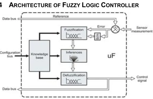
4
A
RCHITECTURE OFF
UZZYL
OGICC
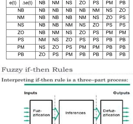
ONTROLLER2876 3.5 if-THEN RULE BASE FOR FUZZY LOGIC CONTROL
e(t) ∆e(t) NB NM NS ZO PS PM PB NB NB NB NB NB NM NS ZO NM NB NB NB NM NS ZO PS NS NB NB NM NS ZO PS PS
ZO NB NM NS ZO PS PM PM
PS NM NS ZO PS PS PB PB PM NS ZO PS PM PM PB PB PB ZO PS PM PB PB PB PB
Fig. 8. Fuzzy processing block diagram
3.6
PID
C
ONTROL3.6.1 INTRODUCTION TO PID CONTROL
A proportional-Integral-Derivative controller (PID controller or three-term controller) is a control loop feedback mechanism widely used in industrial control systems and a variety of other applications requiring continuously modulated control. A PID controller continuously calculates an error value e(t) as the difference between the desired setpoint (SP) and a measured process variable (PV) and applies a correction based on proportional, integral, and derivative terms (denoted P, I, and D respectively). The basic control loop can be simplified for a single-input-single-output (SISO) system as in Fig.10 Here we are neglecting any disturbance present in the system.
Fig. 10 Closed-loop siso system
The controller may have different structures. Different design methodologies are there for designing the controller in order to achieve the desired performance level. But the most popular among them is Proportional Integral Derivative (PID) type, controller. In fact, more than 95% of the industrial controllers are of PID type.
3.6.2 PROPORTIONAL PLUS INTEGRAL (P-I) CONTROL
The advantage of this integral control action is that the steady-state error due to step input reduces to zero. But simultaneously, the system response is generally slow, oscillatory and unless properly designed, sometimes even unstable. With the P-I controller graph of the closed-loop system with the same process is given in Fig. 11.
Fig. 11 The proportional plus integral control action
It is evident from the above discussions that the P-I action provides the dual advantages of fast response due to P-action and the zero steady-state error due to I-action. In the same way, as in integral control, we can conclude that the steady-state error would be zero for P-I action. Besides, the closed-loop characteristics equation for P-I action is Comparing these two, one can easily observe that, by varying the term Kp, the damping constant can be increased. So, we can conclude that by using P- I control, the steady-state error can be brought down to zero, and simultaneously, the transient response can be improved. The output responses due to (i) P, (ii) I and (iii) P-I control for the same plant can be compared from the sketch shown in Fig. 12
Fig. 12 Step comparing among the transient responses with p, I and p-i control
3.7
S
LIDINGM
ODEC
ONTROLLER3.7.1 INTRODUCTION TO THE SLIDING MODE CONTROLLER
2877 space [20]. Hence, sliding mode control is a variable structure
control method. Any variable structure system, like a system under SMC, may be viewed as a special case of a hybrid dynamical system as the system both flows through a continuous state space but also moves through different discrete control modes.
3.7.2
SLIDING MODE CONTROLLER FOR BOOST CONVERTOR For boost and buck-boost dc-dc converters the derivative of the output voltage turns out to be a discontinuous variable and we cannot express the system in canonical form. With output voltage error as a sliding surface, inducing sliding motions in a boost converter results in an unstable sliding regime. For boost and buck-boost converters, the application of sliding mode control for output voltage regulation is not straightforward. Using inductor current control all three topologies of converters are of reduced-order and are equally amenable to the application of sliding mode control. The sliding surface is zero-dimensional and reduces to a sliding point. A cascaded loop structure is used to study the SMC of a boost converter. This control law is implemented using high-speed operational amplifier LM311. It is used in non-inverting Schmitt trigger mode to implement a small hysteresis band around the sliding plane.4.
S
IMULATION ANDV
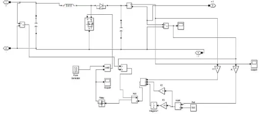
ERIFICATIONFig. 13 Simulation using Matlab software for hybrid renewable energy sources (For Fuzzy Logic and PID)
Fig. 14 VI characteristics of wind power
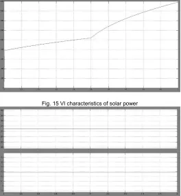
Fig. 15 VI characteristics of solar power
Fig. 16 Boost converter using the fuzzy logic controller
5.1
S
IMULATIONM
ODELO
FF
UZZYL
OGICFig. 17 Boost converter with a fuzzy logic controller
2878 Fig. 18 V-I characteristics of fuel stack cell using the fuzzy logic controller
5.2
S
IMULATIONM
ODEL OFPID
C
ONTROLLERFig. 19 Boost Converter Using PID Controller
Fig. 20 V-I characteristics of boost converter using PID controller .
Fig. 21 V-I characteristics of power at utility grid using PID controller
Fig. 22 V-I characteristics of fuel stack cell using PID controller
5.3
S
IMULATIONM
ODEL OFS
LIDINGM
ODEFig. 23 Simulation using Matlab software for hybrid renewable energy sources (for sliding mode controller)
Fig. 24 Boost converter using a sliding mode controller
2879 Fig. 26 v-i characteristics of the sliding comparator
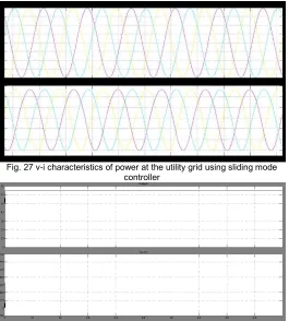
Fig. 27 v-i characteristics of power at the utility grid using sliding mode controller
Fig. 28 V-I characteristics of fuel stack cell using sliding mode controller
6.
C
ONCLUSIONIn this paper, the simulation model on solar, wind and BESS with multiport converter using MATLAB had been presented and also the performance of hybrid renewable energy integrated system is simulated and analyzed by using fuzzy logic controller, PID controller, and Sliding mode controller. Thus, by comparing these three controllers the Sliding mode controller gives better output characteristics. It has shown a successful implementation of Hybrid Renewable energy resources with AC output voltage from different input sources. They are also used as stand-alone applications and operate independently and reliably. Further studies on the method to improve BESS control allowing it to store more energy for more application of the proposed design and also and the proposed topology can improve the consumer side appliance market.
R
EFERENCES[1] P. Prem, R. Bharanikumar, "A New Multilevel Inverter Topology with Reduced Switch Count for Domestic Solar PV Units,"
International Journal of Innovative Technology and Exploring Engineering
(IJITEE), vol. 8, no. 252, pp. 127-131, DEC 2018.
[2] P. Sivaraman and P. Prem, "PR Controller Design and Stability Analysis of Single Stage T-Source Inverter Based Solar PV System,"
Journal of Chinese Institute of Engineers, vol. 40, no. 3, pp. 235-245, APR
2017.
[3] P. Prem, R. Bharani Kumar, "Design and Mathematical Evaluation of a New Multilevel Inverter Topology with Less Circuit Components for Solar and Wind Energy Conversion Systems," Applied Mathematics
and Information Sciences, vol. 11, no. 4, pp 1115-1122, JUL 2017.
[4] P. Prem, Jagabar Sathik, P. Sivaraman, A. Matheswaran and Shady H. E. Abdel Aleem, "A new asymmetric dual-source multilevel inverter topology with reduced power switches," Journal of Chinese
Institute of Engineers, vol., no. 42, pp. 1-13, APR 2019.
[5] A. Matheswaran and C. Ganesh Babu, "Mathematical Modelling and Analysis of Solar PV Based Modified Quadratic Boost Converter for Extraction of Maximum Power," International Journal Applied
Mathematics, vol. 11, no. 5, pp. 1389-1397, SEP 2017.
[6] D. Maksimovic, A.M. Stankovic, V.J. Thottuvelil and G.C. Verghese. “Modeling and simulation of power electronic converters”. Proc.
IEEE vol. 89, no. 6, pp.898 – 912, June 2001.
[7] P. Sivaraman and P. Prem, “Power Quality Enhancement in Distributed Generation Systems", Transactions on Engineering and
Sciences,” vol. 4, no. 1, pp. 20-23, APR 2016.
[8] Ranganathan Gurunathan and K.S. Ashoka Bhat. “A Zero-Voltage Transition Boost Converter Using a Zero-Voltage Switching Auxiliary Circuit,” IEEE Trans.Power Electronics, on Vol. 17, no. 5, pp. 658 – 668, Sept 2002.
[9] Guang Feng, Wanfeng Zhang, and Yan-Fei Liu, “An adaptive current mode fuzzy logic controller for dc-to-dc converters,” Applied Power
Electronics Conference and Exposition, 2003. APEC '03. Eighteenth
Annual IEEE vol. 2, pp. 983 – 989, 9-13 Feb. 2003.
[10] A. Matheswaran, C. Ganesh Babu and R. Sumi, "Design and Analysis of Adaptive Hysteresis Controller for Shunt Active Filter with Pq Control Strategy", International Journal of Applied Engineering
Research (IJAER), vol. 9, no. 24, pp 27557-27568, SEP 2014.
[11] P. Mattavelli, L. Rossetto, G. Spiazzi and P. Tenti, “General-purpose fuzzy controller for dc/dc converters, “Applied Power Electronics
Conference and Exposition, 1995. APEC '95. Conference Proceedings
1995., Tenth Annual Issue 0, Part 2, 5-9 pp. 723 – 730, vol.2, March
1995.
[12] P. Sivaraman and S. Maniprasad, "Reduction of Emi In Cuk Converter For Aircraft Application," International Journal of Applied
Engineering Research, vol. 10, no. 10, pp. 9586-9590, APR 2015.
[13] W. C., & Tse and C. K. “Development of a fuzzy logic controller for DC/DC converters: Design, computer simulation, and experimental evaluation,” IEEE Trans. Power Electronics, 1996.
[14] W.C., Tse, C.K., & Lee and Y.S. “A fuzzy logic controller for DC–DC converter”. IEEE power electronics specialists conference records, 1994.
2880 [16] Guo, J.Y. Hung and R.M. Nelms, “PID controller modifications to
improve steady state performance of digital controllers for buck and boost converters”. IEEE Applied Power Electronics Conference and
Exposition, vol. 1, 2002.
[17] K. Viswanathan, D. Srinivasan and R. Oruganti, “A Universal Fuzzy Controller for a Non-linear Power Electronic Converter,” IEEE
International Conference on Fuzzy Systems, vol. 1, 2002.
[18] P. Sivaraman and A. Nirmalkumar, “Analysis of T-Source inverter with various PWM schemes", European Journal of Scientific Research, vol. 71, no. 2, pp 203-213, NOV 2012.
[19] AElbaset, A. E. Hussein and R.M. Mostafa, "Design and implement of dc-dc converter for photovoltaic systems", International Middle- East
Power Systems Conference, pp.23–25, Dec 2014.
[20] P. Sivaraman and P. Prem, “Dynamic modeling and analysis of T-source electronic inverter using state-space technique,” Scientific