http://www.sciencepublishinggroup.com/j/rst doi: 10.11648/j.rst.20190501.12
ISSN: 2575-5935 (Print); ISSN: 2575-5943 (Online)
Efficiency of Thermoluminescents Dosimeters for Patient
Dose Assessment in Medical Radiology in Antananarivo
Said Soudjay
1, 4, Ramanandraibe Marie Jeanne
1, 3, Ramanantsizehena Georgette Vololona
2,
Raboanary Roland
2, Randriantseheno Hery Fanja
1, Rabesiranana Naivo
1, 2,
Randriamora Tiana Harimalala
11Department of Dosimetry and Radiation Protection, National Institute of Sciences and Nuclear Techniques, Antananarivo, Madagascar 2Department of Physics, Faculty of Sciences, University of Antananarivo, Antananarivo, Madagascar
3
Department of Physics, Faculty of Sciences, University of Fianarantsoa, Fianarantsoa, Madagascar
4Department of Physics, Faculty of Sciences and Technologies, University of Comoros, Moroni, Comoros
Email address:
*
Corresponding author
To cite this article:
Said Soudjay, Ramanandraibe Marie Jeanne, Ramanantsizehena Georgette Vololona, Raboanary Roland, Randriantseheno Hery Fanja, Rabesiranana Naivo, Randriamora Tiana Harimalala. Efficiency of Thermoluminescents Dosimeters for Patient Dose Assessment in Medical Radiology in Antananarivo. Radiation Science and Technology. Vol. 5, No. 1, 2019, pp. 5-10. doi: 10.11648/j.rst.20190501.12
Received: August 22, 2019; Accepted: September 16, 2019; Published: September 30, 2019
Abstract:
In radiation protection of patients and medical exposure control, the Radcal 3036 dosimeter is the standard device used for radiodiagnostic dosimetry in medical field. However, for various reasons, this device is not always available, resulting in service interruptions. This led us to assess the effectiveness of ThermoLuminescent Dosimeters (TLDs) for the same service. This study consists in setting an appropriate protocol, then comparing the surface doses measured by the dosimeter Radcal 3036 and those measured with TLDs. We selected three radiological departments in Antananarivo. For the four standard examinations selected (thorax, skull, abdomen and pelvis), the results show that the differences between the values measured by the two dosimeters remain below to 5%. These results confirm that TLDs offer a credible alternative for measuring the dose received by the patient during medical radiological examination. Dosimetric monitoring breakup can then be avoided, to the benefit of the safety of the public and patients.Keywords:
Thermoluminescents Dosimeter, Diagnostic Radiology, Patient, Dosimetry1. Introduction
The use of ionizing radiation has since its application a real development, especially in the medical field. The difference in attenuation of X-rays by the traversed structures makes it possible to obtain a radiant image made visible by a detector.
The three main areas of radiology are currently: a. scanning
b.Mammography and
c. Conventional radiology (classical)
This latter, who concerns the vast majority of examinations, remains the main source of medical exposure of the population and protective measures must be taken to prevent overexposure or unnecessary exposure of patients. To
ensure the protection of patients, knowledge of the dose he has received during his radiological examination is essential. In radiodiagnostics, the goal of radiation protection of patients is to limit the irradiation to the necessary minimum leading to a quality image.
The Radcal 3036 dosimeter is a standard device used for radiodiagnostic dosimetry. However, for various reasons, this apparatus is not always available, causing interruptions in the quality control of the patient's radiological equipment and dosimetry.
with TLD dosimeters. We evaluated the doses received by patients for some types of standard radiological examinations (Thorax, Abdomen, Crane and Basin) in three radiology departments in Antananarivo:
Avaradoha Health and Care Center (CSS), University Hospital Joseph Ravoahangy Andrianavalona Hospita (CHU-HJRA) and University Hospital Joseph Raseta Befelatanana Hospital (CHU-HJRB).
2. Methods
2.1. Thermoluminescent Dosimeters
Figure 1. Thermoluminescent dosimeters.
This dosimeter contains Thermoluminescent detectors as sensitive elements. These detectors have the property of accumulating a portion of the energy from the incident radiation in metastable energy situations of Thermoluminescents material. As a result of heating, part of this energy is released in the form of visible light. The measurement of the amount of light makes it possible to calculate the dose of radiation incurred. The minimum detectable dose is around 100 µSv. After reading, the detectors can be reused; as a result, they are relatively cheap for a long period of time.
2.2. RADCAL Model 3036 Dosimeter
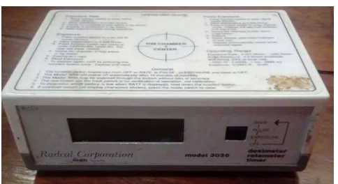
Figure 2. RADCAL model 3036 dosimeter.
The Model 3036 RADCAL Dosimeter is a device used to measure the exposure (in R), the exposure rate (in R / min)
and the exposure time (in ms) of ionizing radiation reaching the detector with ionization chamber. It has three main modes: Exposure Mode, Rate Mode, and Pulse Mode. It has been specifically designed for measuring doses in medical radiodiagnostics. 1R = 8.76 mGy [17].
2.3. Dosimetric Size [2-6, 9]
2.3.1. Kerma (Kinetic Energy Released in Material)
Kerma characterizes the capacity of action of an indirectly ionizing radiation on matter. It is the quotient dEtr by dm, with dEtr is the sum of the initial kinetic energies of all charg)ed particles released by unloaded ionizing particles in a mass dm of a given material.
dm dE K= tr
(1)
The unity of the kerma is the Gy.
2.3.2. Dose in the Air: Da
In the reference conditions, the dose in the air characterizes a radiological installation. Generally, it is measured with an ionization chamber but it can be calculated. The dose in the air Da, expressed in mGy / mAs, is given by formula 2:
( )
2d U k d D
n
a = (2)
With 2 <n <3
U: high voltage applied to the tube
d: focus distance from the tube to the measuring point k: constant depending on the installation
The kerma in air connects with a dose in air by formula 3:
( )
d It DKair = a . (3)
Kair: Kerma in the air expressed in mGy I: current flowing in the tube
t: irradiation time It: charge (mAs)
2.3.3. Determination of the Dose at the Entrance
It is necessary to measure beforehand the dose in the air, Da, at a given reference distance dref of the source (for
example 100 cm), for the beam dimensions practically used. The dose at the entrance surface, De, of the patient is then
calculated as a function of the source-surface area (DSP) distance, the quality of the radiation, for the number of mAs used, for a snapshot according to the formula 4:
2
2
ref e a
ref e air
d
D D FRD mAs
DSP
d
D K FRD
DSP
= ⋅ ⋅ ⋅
= ⋅ ⋅
(4)
3. Results
3.1. Kerma Linearity of the Two Dosimeters
The purpose of this experiment is to verify for both
devices whether the kerma in the air of the X-ray machine is a linear function of the load (mAs). The experiment consists of fixing the high voltage and varying the load. The results are shown in Table 1 for the two dosimeters.
Table 1. Comparison of the linearity kerma of X-ray equipment by the two dosimeters in the three hospitals.
KV=100 CHU-HJRA CHU-HJRB CSS
mAS TLD Radical TLD Radical TLD Radical
25 1,6256 1,5747 0,8744 0,7811 2,7975 2,7734
50 3,2449 3,1454 1,7164 1,7345 5,5951 5,5450
75 4,8675 4,6357 2,6108 2,5997 8,3906 8,3175
100 6,4366 6,2411 3,4500 3,4713 11,1899 11,0900
125 8,1607 8,0112 4,2671 4,4375 13,9875 13,8625
150 9,6911 9,3528 5,2493 5,2987 16,785 16,6350
175 11,4214 10,7375 6,0754 6,0757 19,5825 19,4075
200 12,9798 12,4764 6,8839 7,1175 22,3969 22,1800
Figure 3. Graph of the linearity Kerma.
From the results obtained in Table 1 in the three hospitals, we graphically represented their respective curves in order to verify their linearity. In this figure 3 it is observed that the kerma in the air is linear.
3.2. Debit of Device Measured by the Two Dosimeters
To determine the dose in the air, we fixed the charge and varying the high voltage for a given distance that separates
the source and the two dosimeters. This distance was fixed at 100 cm for the CSS and the CHU-HJRA on the other hand at CHU-HJRB, we realized at 135 cm. For all three hospitals, the load was set at 10 and 20 mAs. We calculated the average of the values obtained with the loads of 10 and 20 mAs. The results are shown in Table 2 for the two dosimeters. Figure 4 shows the variation curve of the dose in air as a function of the high voltage kV.
Table 2. Comparison Debit of radiographic device by two dosimeters in the three hospitals.
kV CSS CHU-HJRA CHU-HJRB
Radical TLD Radical TLD Radical TLD
40 0,0106 0,0133 0,0065 0,0078 0,0036 0,0046
50 0,0221 0,0227 0,0132 0,0145 0,0072 0,0078
60 0,036 0,0365 0,0216 0,022 0,0117 0,012
70 0,0514 0,0518 0,0317 0,0311 0,0173 0,0165
80 0,0699 0,0699 0,0411 0,0396 0,0221 0,0228
90 0,0896 0,088 0,0525 0,0533 0,0283 0,0288
100 0,1113 0,1123 0,0642 0,0649 0,035 0,0351
110 0,1338 0,1332 0,0754 0,0763 0,0414 0,0414
120 0,1642 0,1627 0,0877 0,0886 0,0481 0,0481
From the results obtained in Table 2 in the three hospitals, we graphically represented their respective curves in order to check their flow. In this figure 4 it is observed that the flow of each device has the same characteristics.
3.3. Comparison of the Doses of the Two Dosimeters
We considered fifteen different parameters for each type of examination. For the case of CSS, the distances between the focus of the tube and the skin of the patient are:
a. Thorax face thickness 20 cm: DSP = 88 cm b.Abdomen face thickness 20 cm: DSP = 88 cm c. Skull face thickness 15 cm: DSP = 93 cm d.20 cm thick face basin: DSP = 88 cm e. The FRD is 1.34.
f. For the case of CHU-HJRA and CHU-HJRB the
distances between the tube focus and the patient skin are:
g.Thorax face thickness 20 cm: DSP = 123 cm h.Abdomen face thickness 20 cm: DSP = 123 cm i. Skull face thickness 15 cm: DSP = 128 cm j. 20 cm thick face basin: DSP = 123 cm The FRD is 1.35.
By linear interpolation, using the formula (3), we deduce the values of the other doses in the air corresponding to a given tension.
DES1 represents the dose measured by the thermoluminescent dosimeter, DES2 the dose measured by the Radical 3036 dosimeter and ∆% represents the difference between the two measured values.
Table 3. Comparison of doses measured by Radcal 3036 and TLD for the four selected examination: case of CSS.
Thorax Abdomen Skull Pelvis
DES1 DES2 ∆% DES1 DES2 ∆% DES1 DES2 ∆% DES1 DES2 ∆%
1,1455 1,1683 1,99 1,2436 1,2408 0,23 2,6724 2,6664 0,22 1,1775 1,1889 0,97 1,413 1,4267 0,97 1,5971 1,5902 0,43 3,432 3,4172 0,43 2,4872 2,4817 0,22 1,2095 1,2095 0 3,2795 3,2587 0,63 3,3055 3,2783 0,82 2,6236 2,607 0,63 1,4438 1,4376 0,43 4,1049 4,0712 0,82 3,0642 3,0335 1 4,1399 4,0984 1 0,9838 0,9776 0,63 4,8989 4,8498 1 5,5601 5,5043 1 6,2099 6,1476 1 1,0094 1,0011 0,82 5,1749 5,123 1 6,9563 6,8865 1 10,3757 10,2206 1,49 1,38 1,3661 1,01 6,8235 6,7113 1,64 5,6974 5,6305 1,17 4,6512 4,5682 1,79 2,07 2,0492 1 6,9769 6,8523 1,79 5,9721 5,8829 1,49 4,0638 4,0171 1,15 1,8605 1,8173 2,32 5,9549 5,8679 1,46 9,3702 9,2029 1,79 7,4838 7,4199 0,85 1,6631 1,6489 0,85 8,3153 8,2444 0,85 6,3981 6,3047 1,46 7,8217 7,7984 0,3 1,9641 1,9583 0,3 7,8217 7,7984 0,3 5,2602 5,2445 0,3 12,1671 12,1308 0,3 2,0858 2,0796 0,3 5,3535 5,3375 0,3 8,7619 8,7357 0,3 9,0663 9,0853 0,21 1,3318 1,3313 0,04 5,5848 5,5966 0,21 10,9588 10,9818 0,21 4,627 4,6478 0,45 1,8133 1,8171 0,21 8,3286 8,366 0,45 7,4571 7,4906 0,45 13,4813 13,6025 0,9 2,7199 2,7256 0,21 9,6295 9,716 0,9 9,3284 9,2866 0,45 10,4186 10,4419 0,22
Table 4. Comparison of the doses measured by the Radcal 3036 and the TLD for the four selected examination: case of CHU-HJRA.
Thorax Abdomen skull Pelvis
DES1 DES2 ∆% DES1 DES2 ∆% DES1 DES2 ∆% DES1 DES2 ∆%
Thorax Abdomen skull Pelvis
DES1 DES2 ∆% DES1 DES2 ∆% DES1 DES2 ∆% DES1 DES2 ∆%
0,8352 0,829 0,74 5,7337 5,5324 3,51 7,8854 7,6321 3,21 10,9306 10,579 3,21 1,044 1,0362 0,75 4,5843 4,417 3,65 8,4663 8,1573 3,65 7,3349 7,0672 3,65 1,0949 1,0973 0,22 5,8679 5,6538 3,65 9,1708 9,004 1,82 9,6773 9,2133 4,79
Table 5. Comparison of the doses measured by the Radcal 3036 and the TLD for the four selected examination: case of the CHU-HJRB.
Thorax Abdomen Crane Pelvis
DES1 DES2 ∆% DES1 DES2 ∆% DES1 DES2 ∆% DES1 DES2 ∆%
0,1361 0,1305 4,13 1,5586 1,4943 4,12 2,504 2,3882 4,62 0,5441 0,5386 1,01 0,1407 0,1342 4,6 1,6367 1,561 4,62 2,6313 2,5351 3,65 0,5895 0,5794 1,72 0,1871 0,182 2,72 1,6821 1,6206 3,66 2,6726 2,5994 2,74 0,6367 0,6257 1,72 0,1969 0,1949 1,02 1,7275 1,6802 2,74 2,6819 2,6318 1,87 0,6368 0,6216 2,38 0,2501 0,2475 1,02 1,7729 1,7398 1,87 2,6568 2,6292 1,04 0,7621 0,7391 3,01 0,2018 0,2013 0,27 1,8183 1,7994 1,04 2,9154 2,908 0,25 0,8157 0,7865 3,58 0,2563 0,2556 0,27 1,8638 1,859 0,25 3,0521 3,0672 0,5 1,0525 1,0148 3,58 0,2688 0,272 1,19 1,9092 1,9186 0,49 2,6879 2,7204 1,21 1,0889 1,0441 4,12 0,2166 0,2207 1,9 1,9546 1,9782 1,21 3,0941 3,1527 1,89 1,2098 1,1538 4,63 0,2813 0,2884 2,53 2 2,0378 1,89 3,4379 3,503 1,89 1,2723 1,2257 3,66 0,3594 0,3708 3,17 2,0454 2,0974 2,54 3,0589 3,1367 2,54 0,8315 0,8087 2,74 0,2328 0,2397 2,97 2,0908 2,157 3,17 3,2347 3,317 2,54 1,4629 1,4355 1,87 0,3117 0,32 2,66 2,1495 2,2138 2,99 3,3753 3,4612 2,54 1,5238 1,4953 1,87 0,3279 0,3357 2,39 2,2081 2,2706 2,83 3,3425 3,4483 3,17 1,5003 1,4897 0,71 0,3682 0,3747 1,77 2,2668 2,3273 2,67 3,4862 3,5966 3,17 1,5628 1,5466 1,04
4. Discussion
Both devices should give similar values for the linearity of the Kerma, the flow rate of the device and the evaluation of the dose received by patients during their radiological examinations.
For this we will compare these values to judge the performance of thermoluminescent TLD detectors compared to the dosimeter Radcal 3036 which is the device for dosimetry in radiodiagnostics.
From Figure 3 we have the curves of variation of kerma in the air as a function of load measured by the two dosimeters. In each hospital, the curves are juxtaposed with each other and the equations presented on the graph are similar. These equation curves respectively measured by the Radcal 3036 and the TLD confirm that the kerma is a linear function which shows that the two devices have similar physical characters.
Figure 4 shows the variation curves of the dose in the air as a function of the high voltage measured by the two dosimeters. In each hospital, the curves are juxtaposed with each other and the equations presented on the graph are similar. These equation curves respectively measured by the Radcal 3036 and the TLD confirm that the dose in the air follows the relationship of the type.
( )
2d
U
k
d
D
n
a
=
Avec 2<n<3Tables 3, 4 and 5 give the dose received by the patients during their radiological examination and the difference between the values measured between the TLD and those with the Radcal 3036 dosimeter. DES1 represents the dose measured by the thermoluminescent dosimeter, DES2 dose
measured by the Radical 3036 dosimeter and ∆% represents the difference between the two measured values.
For the case of CSS, with the four types of exams chosen and the fifteen parameters considered, we found that the difference between the measured values remains less than 3%.
For the case of CHU-HJRA, the difference between the measured values remains less than 5%. For CHU-HJRB, the difference between the measured values remains less than 5%. We know that the margin of error in radiotherapy on the dose received by the patients must remain less than 5% gold in conventional radiology the margin of error is more tolerable than in radiotherapy.
These two devices have similar satisfactory physical values, give equal numerical values so Thermoluminescent dosimeters (TLDs) can be used for evaluation of the dose received by the patient. More, they have advantages because, due to its small size, the TLD does not create significant artifacts on the radiological image.
5. Conclusion
by the patient. The results show that the difference between the values measured with the RADCAL 3036 dosimeter, which is a specific device for dosimetry in radiodiagnostics, and those measured with the TLD remain less than 5% in all services.
The thermoluminescents dosimeter has advantages because, due to its small size, it does not create significant artifacts on the radiological image of the patient. This allows their use for dosimetry of the patient according to the type of radiological examination. It is applicable not only in conventional radiology but also in CT and mammography. The presence of a radioprotectionist in radiology services is of paramount importance for the improvement of radiation protection and to ensure the evaluation of the dose received by patients and workers staff.
References
[1] IAEA, the safe use of radiation source, Vienna 1995 N°6. [2] AIEA, Cours post-universitaire de Radioprotection, Vienne,
1995 N°5.
[3] AIEA, Cours Régional Supérieur de Formation sur la Sûreté Radiologique Et le Control des Sources de Rayonnements Ionisants, Vienne Autriche.
[4] AIEA, Cours Régional sur l’autorisation Et Inspection des Sources Rayonnement en Radiothérapie, Mai 2006, Autriche. [5] AIEA, Normes fondamentales de protection contre les
rayonnements ionisants et de sûreté des sources de rayonnements, 1997, Vienne.
[6] INTERNATIONAL COMMISSION ON RADIOLOGICAL PROTECTION, Recommendation of ICRP, Publication 60, Pergamon Press, Oxford and New York, 1996.
[7] CIPR, protection et sûreté radiologique, publication 73, paris.
[8] ALBER LISBONA, control de qualité en radiologie, 2003, Montpellier.
[9] ALBERLISBONA, Dosimétrie des explorations diagnostique radiologie, 2003, Montpellier.
[10] BEAUVAIS, MARCH, Exposition des Patients en Radiodiagnostic, Paris 2003.
[11] MONTAGNE, Imagerie Médicale, Tome 1 deuxième Edition, France 2001.
[12] Said SOUDJAY, mémoire de DEA, évaluation de la performance des dosimètres thermoluminescents pour la dosimétrie du patient en radiologie, janvier 2007.
[13] TLD equipment and materials, Thermoluminescence Dosimetry, THE HARSHAW Chemical Company.
[14] RAZAFINDRABE Rija lalaina, Mémoire de DEA, Etalonnage des Dosimètres Thermoluminescents utilisées en Radioprotection, Madagascar – INSTN 2000.
[15] International Standard Organisation (ISO 4037-1) X and gamma reference radiation for calibrating dosimeters and doserate meters and for deterging their response as a function of photon energy, 12, 15-1996, Suisse.
[16] OFFICE DE PROTECTION CONTRE LES
RAYONNEMENTS IONISANTS ET SOCIETE
FRANCAISE DE RADIOLOGIE, Les procédures radiologiques des critères de qualité et optimisation des doses, Transposition de la Directive 97/43 Euratom, Rapport d’étape du 31 juillet 2000.
[17] RAZAKARIMANANA Tahiry, Doses evaluation of some body organs of pediatric patients undergoing chest X-ray examination using thermoluminescent dosimeter, Science Publishing Group, 2017.