R E S E A R C H
Open Access
A head-mounted goggle-type
video-oculography system for vestibular
function testing
Youngsun Kong
1, Suhwan Lee
2, Jinseok Lee
3and Yunyoung Nam
4*Abstract
Disorders of the vestibular system possibly decrease vision, causing abnormal nystagmus and dizziness. To diagnose abnormal nystagmus, various studies have been reported including the use of rotating chair tests and videonystagmography. However, these tests are unsuitable for home use due to their high costs. Thus, a low-cost video-oculography system is necessary to obtain clinical features at home. In this paper, we present a goggle-type low-cost video-oculography system using an infrared camera and Raspberry Pi board for tracking the pupils and evaluating a vestibular system. Horizontal eye movement is derived from video data obtained from an infrared camera and infrared light-emitting diodes, and the velocity of head rotation is obtained from a gyroscope sensor. Each pupil was extracted using a morphology operation and a contour detection method. Rotatory chair tests were conducted with our developed device. To evaluate our system, gain, symmetry, and phase were measured and compared System 2000.
Keywords: Infrared camera, Video-oculography, VOG, Videonystagmography, VNG
1 Introduction
During human locomotion, vision is disturbed by head perturbations [1]. The vestibulo-ocular reflex (VOR) helps the eyes fix on a target ahead, by rotat-ing the movrotat-ing eyes in the opposite direction [2]. This compensatory eye movement is induced by sens-ing angular acceleration in the semicircular canals of the vestibular system [3]. However, vestibular dysfunc-tion in the form of blurring of vision in that a target slips from the fovea makes an eye movement pattern called nystagmus [4]. Visual acuity can decrease by 50% when an object is only 2° from the center of the
fovea, which can be caused by Nystagmus [5]. In
addition, 35.4% of US adults aged 40 or older had some degree of vestibular dysfunction according to the survey from 2001 to 2004 [6]. There are two gold standard methods to diagnose nystagmus and evaluate the semicircular canals, rotatory chair tests are con-ducted on suspected patients [7]. These tests include
the sinusoidal harmonic acceleration (SHA) test and the velocity step test. The SHA test measures factors that can infer a degree of dizziness by rotating a chair with frequencies of 0.01–0.64 Hz increased by two times in terms of sinusoidal velocity, and by measur-ing eye movement [7]. To analyze eye movement sig-nals with the SHA test, three factors are calculated, which are gain, symmetry, and phase. Each feature represents overall responsiveness, the degree of symmetry between left and right stimuli, and time difference be-tween head stimulus and eye movement. The velocity step test measures vestibular response decay by suddenly chan-ging chair velocity and keeping it constant [7]. However, the SHA test is preferred generally due to limitations with the velocity step test that includes the need for a powerful chair, lower reliability, and more stress to the patient [7]. In this study, only SHA tests were conducted.
Electronystagmography (ENG) and scleral search coil systems (SSCSs) were used to collect eye
move-ment signals [8, 9]. ENG measures movements of
the eye by attaching electrodes around the nose, while ENG has the advantages of being able to make measurements while the eyes are closed; ENG has * Correspondence:[email protected]
4Department of Computer Science and Engineering, Soonchunhyang University, Asan, South Korea
Full list of author information is available at the end of the article
disadvantages of artifacts being caused by eye blink-ing, perspiration, or light, and difficulty in measuring vertical eye movement. Additionally, SSCS requires subjects to attach an annular contact lens to their eyes; although having a high accuracy and sampling rate, it can be worn for only 40 min and has a tendency to slip [10, 11]. With advances in computer vision technology, video-nystagmography (VNG) has been used generally, although ENG data are still valuable [12]. VNG is a technology that can test whether dizziness is caused by inner ear disease; it uses an infrared camera to track the pupil in the dark. Ad-vantages of VNG are its high accuracy and non-invasive nature, making its use common, although with high cost.
Various VNG researches using VNG have been conducted [13–17]. In [13], researchers suggested a new method to solve the problem of estimating the eye pos-ition in VNG analysis brought about by deformable contour methods. They suggested a method based on pos-ition, amplitude, and duration that could track saccade movement with high accuracy. In [14], a method of vestibular disease analysis for VNG applications was pro-posed, and new features were suggested based on Fisher’s criteria for the diagnosis of nystagmus. In [15], researchers proposed a method for medical characteristic analysis with the displacement vectors of nystagmus using Gaussian mixture models (GMM). Video data were captured using
infrared cameras, and two-dimensional displacement vec-tors were calculated by comparing two adjacent frames. Then, GMM was applied to analyze the vectors. In [16], researchers compared the features extracted from the diameter and position of an eye recorded using VNG on patients and normal subjects. In [17], researchers analyzed VNG dataset based upon the fundamental measurements of normal and patients who have vestibular disorder by using a neural network to develop the assessment of vertigo symptom.
Various commercial VOG products have been de-veloped [18, 19]. They conduct and analyze results in SHA test, velocity step test, and optokinetic nys-tagmus test by measuring pupil movements with a rotatory chair and VOG to monitor vestibular loss, dizziness, and chronic imbalance. Also, they are highly accurate systems but with high cost and used only in hospitals.
In this paper, a pair of head-mounted goggles was built with an infrared camera and used with a rotatory chair to conduct SHA tests. Then, pupil coordinates were extracted from the video data. From the pupil data, gain, phase, and symmetry were calculated for measuring rapid eye movements. Finally, these factors were compared with System 2000 [18] results, which is a highly accurate system that measures pupil move-ments with a rotatory chair and infrared cameras and analyzes vestibular system, but it is expensive.
Fig. 1Head-mounted goggles with an infrared camera.aGoggles inside.bRaspberry Pi 3.cIR LED
Fig. 2PCB circuit of the goggles
Fig. 3Infrared images of a pupil.aSystem 2000.bDeveloped goggles
2 Methods
2.1 Prototype
Head-mounted goggles were designed for obtaining eye movement signals. Figure 1 shows a pair of head-mounted goggles with an infrared camera and a gyro-scope sensor. The goggles can record infrared videos of the right eye of the subject and measure rotatory velocity. To conduct a calibration, the participant can see the front with the left side of the goggles. The measured field of view is 32°. Three 850-nm light-emitting diodes (LEDs) were attached to the goggles. To avoid noise caused by light reflexes, the LEDs were located at the bottom. The distances from the center were approximately 1.5, 1.9, and 2.9 cm from the left to the right LED. The prototype complies with International Standard IEC 60825-1 [20].
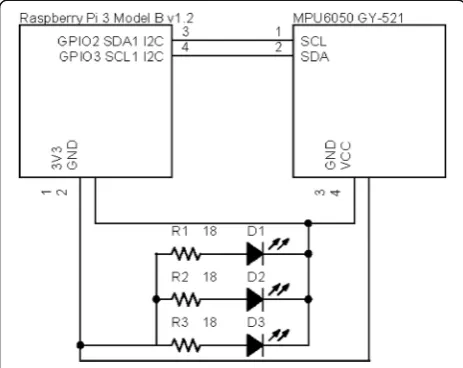
The prototype consists of an infrared camera, a gyroscope sensor, and infrared LEDs. 3D virtual real-ity (VR) glasses (Maruneuru, Korea) were used as the frame for the goggles. Figure 2 shows a printed circuit board (PCB) for the goggles. The Raspberry
Pi 3 model B (Raspberry Pi Foundation, UK) [21]
was used with the goggles for image processing and calculating features, due to its low cost, appropriate size, and fair image processing performance. Add-itionally, a Pi Camera (v2) without an IR filter, equipped with a IMX219 8-megapixel sensor (Sony, Japan) [22], was used to capture infrared images of
the eyes. A gyroscope MPU-6050 (InvenSense, USA) [23] was used to measure the angular velocity of the goggles.
2.2 Pupil extraction
To obtain horizontal eye movement, the pupil was extracted from video data obtained with the goggles
and the System 2000; Fig. 3 shows screenshots of a
healthy subject. Because pupils have a generally circu-lar shape, the same method was used to both video data obtained from the goggles and the System 2000 with different threshold values of brightness and pupil size. The method includes noise removal and a circle-detection algorithm.
To decrease the miss rate, the ROI was selected from raw images. The sizes of the ROIs for the de-veloped goggles and the System 2000 were set at 200 × 210 and 400 × 200, respectively. Figure 4 shows a gray image and the result of image binarization. Because video data were obtained as RGB images, the gray channel was extracted from the infrared video data. The intensity of the pupil area is higher than that of the rest; thus, binary images were ob-tained from the extracted gray channel with manual threshold values for each subject. Binary images may contain noise caused by occlusion by the eyelids and eyelashes.
To solve the noise issue, a morphology operation was implemented (Fig. 5), whose kernel was set as 3 by 3 rectangular structuring element, and iterations
Fig. 5Morphology operation. aErode. bDilation.cErode and dilation
Table 1Miss rate with morphology and no morphology
Subject Miss rate with morphology Miss rate without morphology
1 27.4% 47.2%
2 41.6% 92.5%
3 14.0% 46.7%
4 7.1% 78.9%
5 6.3% 24.7%
6 30.5% 75.6%
7 27.5% 51.7%
8 18.3% 66.0%
9 8.3% 100.0%
10 8.3% 82.6%
Fig. 6Example of detected pupil
were manually set for each subject. Table 1 shows the pupil miss rate, estimated from images where the morphology operation was and was not applied. The pupil miss rate is given by the following:
Miss rateð Þ ¼%
P
False negative
P
Condition positive; ð1Þ
Average of the miss rate is approximately 18.54%. Finally, FindContours function in OpenCV library was applied to detect a circular region. The contour candi-dates were selected by the following equations:
abs 1−w
h
<k; ð2Þ
abs 1− s π∙ w
2 2
!
<k; ð3Þ
ample of an image with the method applied.
2.3 Slow-phase eye movement
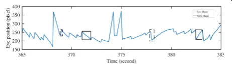
Figure 7 shows a part of the eye movement signal ob-tained from the goggles. The dashed rectangles and the solid rectangles indicate fast-phase and slow-phase eye movement, respectively. To extract features from eye-movement signals, the slow-phase velocity of the pupil should be calculated [24].
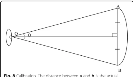
A degree per pixel value was assumed to determine the velocity of horizontal eye movement in degrees. Figure 8 shows a calibration method for obtaining degrees per pixel. The Ɵvalue was calculated using a trigonometric function. Also, degrees per pixel for the goggles and the System 2000 were calculated by dividing Ɵ by AB . Finally, gain, sym-metry, and phase were calculated from the signal.
2.4 System 2000
Slow-phase velocity is derived from the raw signal as shown in Fig. 9. First, the horizontal pupil movement signal was extracted from the infrared video data using a pupil extrac-tion method. Missing frames caused by eye blinking were set as a negative number. In compensating for missing frames caused by eye blink artifacts, a linear spline algo-rithm was implemented. Moreover, a cubic spline algoalgo-rithm
Fig. 8Calibration. The distance betweenaandbis the actual diameter
was implemented to interpolate the signal to 30 Hz due to the irregular sampling rate (27–29 fps). Pupil velocity was also derived from the interpolated signal.
The fast phase of the signal was removed as follows. Since having a larger slope than the slow-phase velocity, the fast-phase velocity was determined based on slope degree. First, the obtained signal was normalized with a mean of 0 and a standard deviation of 1. Then, the eye movement signal was derived and squared, to obtain the slope of the signal. Peaks were detected by a threshold value from the squared signal, which were manually set based on each velocity of chair. As shown in Fig.10, the red line represents the fast phase obtained. Finally, the fast phase was removed from the derived signal.
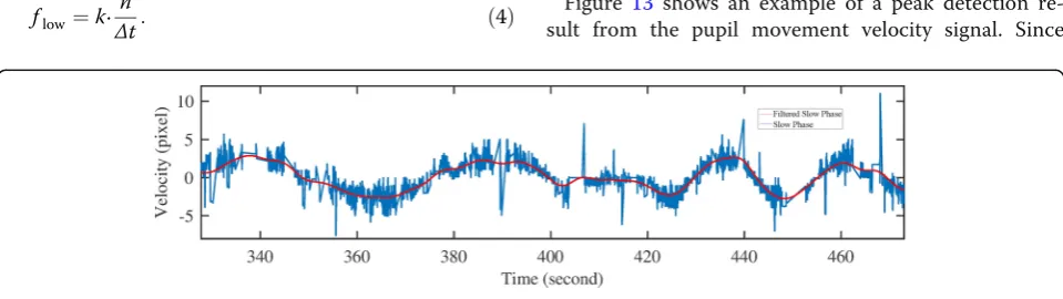
After the fast-phase signal was eliminated, a linear spline algorithm was used. As shown in Fig.11, low-pass filter was applied to remove noise from the velocity sig-nals. The cut-off frequency of the low-pass filter was set as follows:
flow¼k∙ n
Δt: ð4Þ
where k, n, and Δt represent a constant, the number of cycles, and the period, respectively, corresponding to the frequency of head movement multiplied by a constant. The constant values were manually set between 1 and 2 for each subject.
2.5 Designed goggles
The infrared camera used in the goggle design had a lower resolution and sampling rate than those of the System 2000. Thus, a different method was used to obtain the slow-phase signal and features calculated with the camera. Slow-phase velocity is derived from the raw signal as shown in Fig. 12. A negative num-ber indicates that the pupil was not detected due to noise, such as eye blinking and low sampling rate. Then, raw signals were interpolated using a linear spline algorithm to remove missing frames. Because the sampling rate of the signals obtained from the goggles was irregular (25–30 fps), signals were inter-polated using a cubic spline algorithm.
Figure 13 shows an example of a peak detection re-sult from the pupil movement velocity signal. Since
Fig. 10Pupil movement signal (System 2000).aNormalized signal.bDerived signal.cFast phase
the signals obtained between the designed goggles and System 2000 contain different levels of noise and have different frequencies, another method was used
to find peaks. The ‘Findpeaks’ function in MATLAB
was used to find each peak and the valley location. Yellow and red circles represent valley and high peaks of the signal, respectively. The velocity differences be-tween adjacent peaks and valleys were calculated. Vel-ocities that were less than the rotatory chair velocity were removed to eliminate fast-eye movement.
Moving-average and low-pass filters were then ap-plied to remove noise. Figure 14 shows filtered signals with moving-average and low-pass filters. The same equation of cutoff frequency was applied, which is based on the frequency of head movement multiplied by a constant value.
2.6 Gain, asymmetry, and phase
Gain is the ratio of the amplitude of the eye move-ment to the amplitude of head stimulus [25]. Sym-metry is indicated by comparable left and right responses when the same stimulus is applied [25].
Phase is the timing relationship between the initi-ation of head movement and the reflexive eye
re-sponse [24]. Gain, symmetry, and phase are
calculated as follows:
Gain¼Amplitude of the maximum slow phase eye velocity Amplitude of the maximum stimulus velocity ;
ð5Þ
Symmetry¼ b2−b1
b2þb1
100; ð6Þ
Phase φ° ¼360°∙f∙Δt; ð7Þ
where b1 and b2 represent the maximum velocity of slow-phase eye movement in rotating to the left and right, respectively, frepresents the frequency of the eye movement signal, and Δt represents the time difference between the maximum velocity of slow-phase eye move-ment and head movemove-ment.
Fig. 12Pupil movement signal (designed goggles).aRaw signal.bInterpolated signal.cDerived pupil velocity
3 Results
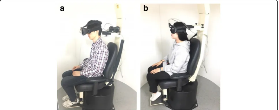
3.1 Acquisition
Data were collected from eight healthy non-smoking men and two women aged from 20 to 28 years. All subjects wore the developed goggles and System 2000 goggles, while seated on a rotatory chair (System 2000) in the sit-ting position (Fig. 15). Each experiment was performed seven times (from 0.01 to 0.64 Hz). The chair was rotated with maximum velocity from 80° to 20° per second for 2 to 8 cycles (Table2). The videos from the goggles were re-corded at 600 × 420 resolution. The videos from the Sys-tem 2000 were obtained using the built-in camera on a Galaxy S6 (Samsung, Korea) at 1920 × 1080 resolution by pointing the monitor of the computer, because no video data are ordinarily provided by the System 2000 and be-cause of the limitation of accessing the computer. Both video data sets were recorded at ~ 30 Hz.
3.2 System 2000
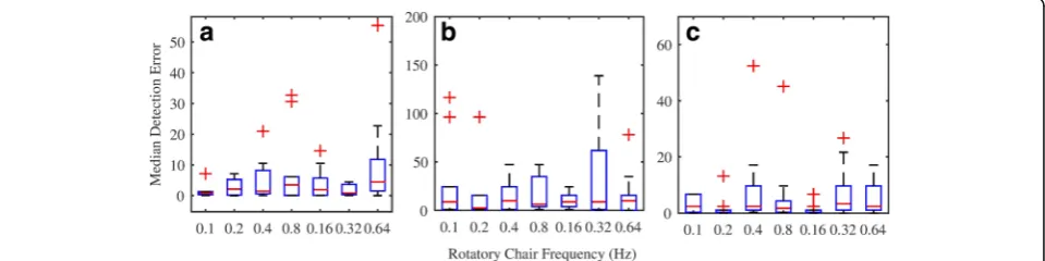
Reference results were obtained from a System 2000 software itself. To evaluate the results, we calculated the errorεfor each frequency of gain, phase, and symmetry, as follows:
ε¼mean absð ðx−xestÞÞ2
mean absð ð Þx Þ2 ; ð8Þ
where x and xest represent the reference and estimated feature, respectively. Each error for gain, phase, and symmetry were measured among all subjects for each frequency. Figure16shows the median and interquartile range (IQR) of the errors measured from the results at each frequency. The mean errors for gain, symmetry, and phase were 0.81, 17.35, and 2.74, respectively. Fig. 14Pupil movement signal (designed goggles).aMoving average.bLow-pass filter
Figure 17 shows Bland–Altman and correlation plots of gain, symmetry, and phase with mean differ-ences of 0.047, 0.16, and 0.029, respectively; the solid lines and the dashed lines in part (b) of each figure represent the regression line and a Pearson correl-ation coefficient of 1.
3.3 Designed goggles
It is hard to wear two goggles simultaneously with-out creating noise. Thus, we calculated the features and the coverage rate that measures how many re-sults of the features are in the range of the refer-ence data. The experimental setup was set to the same values used with the System 2000. The cover-age rates for gain, symmetry, and phase were 66, 87, and 70%, respectively.
4 Conclusions
This paper has presented a low-cost VNG using an infrared camera for the diagnosis of nystagmus by obtaining eye movement features. The device was de-veloped using a pair of head-mounted goggles, a Raspberry Pi board, an infrared camera, and LEDs. To extract and track the pupil from video data ob-tained from the device, a morphology operation and a contour detection method were used. The miss rate was 18.54% when applying the morphology operation, whereas without applying it, the rate was 66.9%. The horizontal eye movement signal was obtained, and its
slow-phase velocity was calculated. Gain, symmetry, and phase were calculated from the velocity of hori-zontal eye movement and evaluated in 10 healthy subjects. Interpolation algorithms were used to detect missing signals caused by eye blinking in the subjects. Also, video data for the System 2000 are slightly tilted because of being captured by pointing the monitor of the computer and had minor oscillation noise caused by movements of subjects. Accordingly, the average IQR errors of gain and phase were 0.81 and 2.74, while that of symmetry was 17.35.
Because some images were misdetected due to noise caused by a low frame rate of IR camera and occlusion by eyelids and eyelashes, the relative high miss rate of pupil detection and the IQR errors was shown. Moreover, thresholds to detect pupil, to cal-culate degree per second, and frequency filtering factors are manually selected for each subject. Add-itionally, the number, location, and wavelength of the LEDs were not verified in the experiments. Also, relatively long missing frames with interpolation methods may cause minute distortion to signal and high IQR errors. Moreover, the developed goggles were not evaluated with a clinical device, because it is impossible to use two sets of goggles simultan-eously without generating noise. In the future, more experiments will be conducted on more subjects in-cluding patients who have vestibular diseases for clinical tests. Also, we will evaluate the goggles
0.08 50 5
0.16 40 5
0.32 30 6
0.64 20 8
using other tests, such as the velocity step test to compare between the developed goggles and other clinical equipment. In addition, we will develop a VOG system that records pupil and angular velocity using an infrared camera and a gyroscope with any swivel chair at home.
Abbreviations
ENG:Electronystagmography; GMM: Gaussian mixture models; IQR: Interquartile range; LEDs: Light-emitting diodes; PCB: Printed circuit board; SHA: Sinusoidal harmonic acceleration; SSCSs: Scleral search coil systems; VNG: Videonystagmography; VOR: Vestibulo-ocular reflex; VR: Virtual reality
Acknowledgements
The authors would like to thank Namik Kim and Hyeonsu Lee for his valuable contribution to this project.
Funding
This work was supported by the Soonchunhyang University Research Fund and also supported by the“ICT Convergence Smart Rehabilitation Industrial Education Program”through the Ministry of Trade, Industry & Energy (MOTIE), and Korea Institute for Advancement of Technology (KIAT).
Availability of data and materials
The datasets used and/or analysed during the current study are available from the corresponding author on reasonable request.
Authors’contributions
YK and YN conceived and designed the study. YK and SL performed the experiments. YK and YN wrote the paper. JL and YN reviewed and edited the manuscript. All authors read and approved the final manuscript.
Competing interests
The authors declare that they have no competing interests.
Publisher’s Note
Springer Nature remains neutral with regard to jurisdictional claims in published maps and institutional affiliations.
Author details
1Department of Biomedical Engineering, University of Connecticut, Storrs, CT, USA.2Department of ICT Convergence Rehabilitation Engineering, Soonchunhyang University, Asan, South Korea.3Department of Biomedical Engineering, Wonkwang University School of Medicine, Iksan, South Korea. 4Department of Computer Science and Engineering, Soonchunhyang University, Asan, South Korea.
3. JL Meiry, The Vestibular System and Human Dynamic Space Orientation (1966). 4. JM Epley, Positional vertigo related to semicircular canalithiasis. Otolaryngol
Head Neck Surg.112(1), 154–161 (1995)
5. DS Zee,The Neurology of Eye Movements [Electronic Resource](Oxford University Press, Oxford, 1999)
6. Y Agrawal, JP Carey, CC Della Santina, MC Schubert, LB Minor, Disorders of balance and vestibular function in US adults: Data from the National Health and nutrition examination survey, 2001-2004. Arch. Intern. Med.169, 938 (2009) 7. TC Hain, Rotatory Chair Testing (2016),https://www.dizziness-and-balance.
com/testing/ENG/rchair.html. Accessed 15 Apr 2018 8. LB Jongkees, Electronystagmography. Hno12, 325 (1964)
9. DA Robinson, A method of measuring eye movement using a scleral search coil in a magnetic field. IEEE Trans. Biomed. Electron.10, 137 (1963) 10. ST Moore, T Haslwanter, IS Curthoys, ST Smith, A geometric basis for
measurement of three-dimensional eye position using image processing. Vis. Res.36, 445 (1996)
11. T Imai, K Sekine, K Hattori, N Takeda, I Koizuka, K Nakamae, K Miura, H Fujioka, T Kubo, Comparing the accuracy of video-oculography and the scleral search coil system in human eye movement analysis. Auris Nasus Larynx32, 3 (2005)
12. MM Ganança, HH Caovilla, FF Ganança, Electronystagmography versus videonystagmography. Braz. J. Otorhinolaryngol.76, 399 (2010) 13. AB Slama, AN Machraoui, M Sayadi, inImage Processing, Applications
and Systems Conference (IPAS), 2014 First International. Pupil tracking using active contour model for videonystagmography applications (IEEE, Sfax, 2014), pp. 1–5
14. AB Slama, A Mouelhi, MA Cherni, S Manoubi, C Mbarek, H Trabelsi, M Sayadi, inAdvanced Technologies for Signal and Image Processing (ATSIP), 2016 2nd International Conference on. Features extraction for medical characterization of nystagmus (IEEE, Monastir, 2016), pp. 292–296 15. Y Mao, Q Wang, J Miao, W He, inBiomedical Engineering and Informatics
(BMEI), 2013 6th International Conference on. An application of Gaussian mixture models for medical characteristics analysis of nystagmus signals (IEEE, Hangzhou, 2013), pp. 18–23
16. H Salwa, W Turki, M Sayadi, inImage Processing, Applications and System Conferences (IPAS), 2014 1st International Conference, At Sfax. Study of the correlation between pupil position and diameter in video-nystagmotraphy for nystagmus analysis (2014), pp. 1–4
17. AB Slama, A Mouelhi, H Sahli, inIndustrial Electronics Society (IECON), 2016 42nd Annual Conference on. A novel automatic diagnostic approach based on nystagmus feature selection and neural network classification (IEEE, Florence, 2016), pp. 5165–5170
18. Micromedical, System (2000),http://www.micromedical.com/Products/ Rotational-Chairs/. Accessed 15 Apr 2018
19. Vestlab, Vestlab OS.http://www.vestlab.de/produkt_en.html. Accessed 15 Apr 2018
20. International Electrotechnical Commission. Safety of Laser Products–Part 1: Equipment Classification and Requirements. Geneva, Switzerland. IEC-60825-1, (2014)
21. Raspberry PI Foundation, Raspberry Pi 3 model B.https://www.raspberrypi. org/products/raspberry-pi-3-model-b/. Accessed 15 Apr 2018
22. Sony, IMX219.http://www.sony-semicon.co.jp/products_en/new_pro/april_ 2014/imx219_e.html. Accessed 15 Apr 2018
23. InvenSense, MPU-6050. https://www.invensense.com/products/motion-tracking/6-axis/mpu-6050/. Accessed 15 Apr 2018
24. MS Amin, Rotary Chair Testing: Overview, Indications, Equipment. (2016),https:// emedicine.medscape.com/article/1832765-overview. Accessed 24 Feb 2016. 25. PN Tandon, R Ramamurthi,Textbook of Neurosurgery, Third Edition, Three