Article
Multi-objective Optimization of Draft Tube in
Francis Turbine Using DOE, RBF and NSGA-II
Chol Nam Mun, De Chun Ba*, Xiang Ji Yue and Myong IlKim
School of Mechanical Engineering & Automation, Northeastern University, Shenyang 110819, China; [email protected], [email protected], [email protected], [email protected]
* Correspondence: [email protected]; Tel.: + 86-24-8368-3851
Abstract: In order to improve the performance of the draft tube in hydraulic turbine, a multi–objective optimization method for the draft tube is developed by combining the design of experiment (DOE), the radial basis function (RBF) and the non–dominated sorting genetic algorithm (NSGA–II) in this paper. The geometrical design variables of the median section in the draft tube and the cross section in its exit diffuser are considered as design parameters in this optimization, which objective function is to maximize the pressure recovery factor (Cp) and minimize the energy loss coefficient (ζ). The limited numbers of design matrix required for the shape optimization of the draft tube is generated by optimal Latin hypercube (OLH) method of the DOE technique, of which performances are evaluated through computational fluid dynamic (CFD) numerical simulation. For reducing of the computational consumption, the approximate model is used based on the RBF. The Pareto optimal solutions are finally performed using the NSGA–II for obtaining the best geometrical parameters of the draft tube. The optimization result of the draft tube shows a marked performance improvement over the original, which verifies the theoretical validity and feasibility of the proposed method in this paper.
Keywords: francis turbine; draft tube; optimization design; experiment of design; non–dominated sorting genetic algorithm
1. Introduction
Hydraulic energy is one of the important energy sources to meet the growing needs of energy, being renewable energy resources. Therefore, the improvement of the efficiency by renovating and upgrading of the hydraulic turbine is a challenging task in old hydropower plants, which is greatly affected by the performance of the draft tubes in hydraulic turbine. The main role of the draft tube is to convert the remaining kinetic energy into the static pressure at the runner outlet. The draft tube can be classified into two groups; straight and curved shapes. Generally, the straight shape of the draft tube has a good hydraulic characteristic, but it is used only at the small and medium diameters of the runner, because of the huge construction cost of the long vertical draft tubes. While the curbed shape of the draft tube is used at the hydraulic turbine with the large diameter of the runner to reduce the excavation depth of the draft tube. Traditionally, the design of the draft tubes has been performed through the experience of the designers and the model tests.
Many investigations have been carried out by using the CFD for the performance calculation, the analysis and the optimization design of the draft tubes in the hydro power plants. Soni V et al. [1] investigated the effects of the suction cone height in the draft tube on the performance of Francis turbine. The results of the numerical simulations using CFD were reported, in which the several permutation and combination of the geometrical parameters such as the suction cone, elbow and exit diffuser were achieved to improve the performance of the curved draft tube. Similar method was adopted on the hydraulic turbine with the straight conical draft tube [2]. Prasad et al. [3] studied on the optimal design by varying the geometric parameters such as the length and height of the elbow in the draft tube at different mass flow rate using 3D viscous flow simulations, in which the geometrical parameters of the best performance from numerical simulation were close to height
ratio of 2.24 and length ratio L/D1 of 6.0. Marjavaara et al. [4] carried out the optimization design of the Turbine–99 draft tube using response surface methodology( RSM), in which the curvature radius of the draft tube was taken as variable and the average pressure recovery factor and the energy loss factor were taken as the objective function. The computed result showed that the optimization results were similar to the experimental, confirming the application possibilities of these techniques in optimal design process. Nakamura K et al. [5] performed automatically the optimization design by combining the design software, CFD solver and MOGA for the optimization of the runner and the draft tube shape of a Francis turbine with high specific speed. As a result, they suggested that this optimization system could be used as the engineering development tool of the Francis turbine. Fares et al. [6] performed the optimization of the curved draft tube in tandem with genetic algorithm and CFD, in which four Bezier control points in the (X–Y) coordinate and ten distribution curve of Z–direction described by Bezier curve technology were employed as design variables, showing the obvious increase in its performance. Meanwhile, because the process of the shape optimization of the draft tube is realized by many iterative calculations using CFD, it requires many time and manpower. Therefore, the automatic optimization methodologies using the geometrical parameters of the cross–sections of the draft tube were previously examined, but these methods had not considered the geometrical parameters such as the median section affecting significantly on the performance of the draft tube [7–9]. While, the multi–objective optimization methods have been employed in the optimization design of turbomachinery [10–12], and the optimization methods in the engineering design have been also suggested using the CFD, DOE technique and multi–objective genetic algorithm [13–15].
This paper presents the methodology to optimize the performances of the draft tube, in which the median section and the cross section of the exit diffuser of the draft tube are selected as geometrical design variables, and two objective functions as maximizing of the pressure recovery factor and minimizing of the energy loss coefficient in flow. The design space is determined by OLH method in DOE technique, and the response values of the selected design matrix are performed through CFD numerical simulation. The results are used to determine and validate an approximate model. Finally, the Pareto optimal solutions using the NSGA–II are carried out to improve the performance of the draft tube.
2. Design Parameters and Objective Function
2.1. Design Parameters
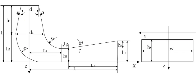
One of the most important problems in the optimal design of draft tube is to select the key geometric factors affecting on its performance as possible, because the computational consumption is highly influenced by the number of the geometric parameters.
h h1
h2
α d3 α
h3
θ h
4
L L1
L3 d4
L2
h5
X
Z Z
Y
w h5
Figure 1. Geometric parameters of the elbow draft tube.
While the increment at the height (h1) of the discharge cone helps to obtain a uniform flow leaving from the runner outlet, but it results in the increase of the hydraulic loss because of the decrease in the curvature radius of the elbow portion if height (h1) is larger. Therefore, how to set up the rational ration of h1 and h2 is very important. The discharge cone part can be featured either by the divergence angle α and cone height h1 or by cone height h1 and diameter d4, the cone height h1 and diameter d4 used in this paper used in this paper. And the curvature radius (r1), (r2) and elbow height (h2) of the draft tube describe the geometrical range of the elbow part through the change of their sizes. The reasonable size of height (h3) can be decreased the hydraulic losses from the elbow–induced secondary flows, and the height (h3) of exit diffuser is an important geometrical parameter for the discharge balance between the elbow portion and exit diffuser. The purpose of the exit diffuser is to connect the elbow portion and the tailrace for achieving the higher recovery of the pressure from flow downstream in an elbow. Therefore, the exit diffuser should be considered to minimize the flow separation and reverse flow. Flow separation and reverse flow in the exit diffuser can be effectively controlled by parameters L, L2, L3, h4, θ, and h5. Because L is constant while the diffuser angle (θ) can be described as a function of h4 and L3, and L3 can be described as a function of the length L. Therefore, the exit diffuser can be indicated by the parameters L, L2 and h4. Combining the median section and cross–section is reasonable in the optimization the performance of the draft tube, because the cross–sections of draft tube affect on its performance. Thus, the free geometric parameters for optimization design of the draft tube are ten parameters: h1, h3, h4, d4, L1, L2, r1, r2 and w.
2.2. Objective Function
The choice of the objective function for the optimization design is very important for the successful solution. The objective function for the performance evaluation of the draft tube is characterized by two parameters: the pressure recovery factor (Cp) and the energy loss coefficient (ζ). It is desirable that Cp is great as possible in the optimization process. The Cp indicates the degree of converting of the kinetic energy to the static pressure where a higher value means higher efficiency for the draft tube. The pressure recovery factor is defined as follows:
2
1
(
)
2
out in
p
in
in
p
p
C
Q
A
ρ
−
=
(1)where Pin is the static average pressure at the inlet of the draft tube, Pout is the static average
system. It means the total pressure loss from the inlet to the outlet compared to the inlet kinetic
energy. The energy loss coefficient is defined as:
2
1 1
1 ( ) 2
t t
in out
in out in in
PdA PdA
A A
Q A
ζ
ρ −
=
(2)where Ain is the cross–section area of the inlet, Aout is the cross–section area of the outlet, Pt is the
total pressure.
The optimization problem is mathematically formulated as follows:
( )
( )
1 2
1 3 4 4 1 2 1 2
: and : : , , , d , , , , subject to: X X
) (
X p
lb ub
maximize f X C minimize f X
over X h h h L L r r w
ζ
= =
=
≤ ≤
(3)
where X is the set of the geometrical parameters of draft tube, f1(X) and f2(X) are the objective
functions for the pressure recovery factor and energy loss coefficient, respectively, Xlb and Xub is the
lower and the upper bounds of the design space for each geometrical parameters while the
constraint conditions of the each geometrical parameters is described in Table 1.
3. CFD Numerical Simulation
3.1. Modeling and Meshing
spiral case
stay vane
runner draft tube guide vane
Figure 2. 3D model of Francis turbine.
3.2. Numerical Simulation
ANSYS FLUENT16.1 is utilized to investigate the flow field of the draft tube, which solves 3D Reynold –Averaged Navier–Stokes equations with the steady state. And Shear Stress Transport (SST) k–ω turbulence model proposed by Menter [17] is applied for the turbulence treatment. The SST k–ω turbulence model equations are:
( ) ( ) ( ) ( ) j i i
k k k k
i j
i j
j
u
G Y D S
t x x
ku
k k
G Y S
t x x x x ω ω ω ω ω ρ ρω ρω ω ρ ∂ ∂ ∂ ∂ ∂ ∂ ∂ + = Γ + − + ∂ ∂ ∂ ∂ ∂ + = Γ + − + + ∂ ∂ ∂ ∂ (4)
where Gk is the turbulent kinetic source term, Γk and Γωare the effective diffusion coefficients for k
and ω, Gω is the dissipation equation source term, Yk and Yω are the divergence terms for k and ω,
Dω is the orthogonal divergence term, Sk and Sk are user–defined source terms.
The SIMPLEC algorithm is adopted to realize the pressure–velocity coupling. The SST model is suggested for the high accuracy of the boundary layer simulation, which can give a more reliable simulation result for flows around complex objects, flows with inverse pressure gradient, transonic flows, etc. The inlet boundary condition is specified as the total pressure at the spiral case inlet and the pressure outlet is specified at the draft tube outlet. The non–slip wall boundary condition is adopted. The standard discretization scheme is employed for the pressure, while the momentum, turbulence kinetic energy and turbulence dissipation rate are used as the second–order upwind scheme. The under–relaxation factor is applied as the default value.
4. Optimization Procedure
4.1. Design of Experiment
design, which can solve the optimal problem and conduct the sensitivity analysis for the design space. The OLH is a modified Latin Hypercube design, which generate more evenly distributed the sample points than other DOE strategy [18, 19]. The OLH method provides the regular sample points between the lower and upper bounds. In this paper, 140 sets of the sample points are generated using the OLH method in the DOE technique. Here, the constraint conditions of the each geometrical parameter are described in Table 1.
Table 1. Design variable and constraint values at initial design.
Variable Description Lower Bound Initial design Upper bound
h1 The height of discharge cone 352.7 391.89 431.08
h3 The inlet height of exit diffuser 594.02 660.02 726.03
h4 The diffuse height of exit diffuser -186.62 -169.65 -152.68
d4 The inlet diameter of elbow 171.84 190.94 210.03
L1 The length of elbow 379.73 421.92 464.11
L2 The length of elbow extension 85.869 95.41 104.95
r1 The inner radius of elbow 211.11 234.57 258.03
r2 The outer radius of elbow 336.34 373.71 411.08
w The width of exit diffuser 358.04 397.83 437.61
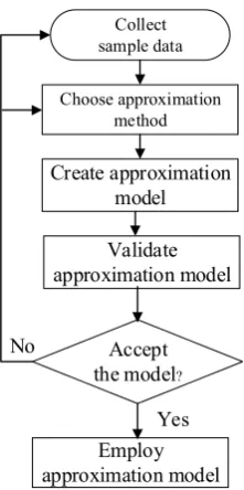
4.2. RBF Approximation
Employ approximation model
Accept the model? Create approximation
model Choose approximation
method
Yes No
Collect sample data
Validate approximation model
Figure 3. Construction process of approximate model.
4.3. Design Exploration Using NSGA–II
Based on the validated approximate model, the optimization problem is to find a new set of the geometric parameters to maximize Cp and minimize ζ. Both of these objectives conflict each other, there is no the best solution to satisfy these objectives simultaneously [21]. Hence, this solution can be called Pareto solution. Generally, multi–objective optimization problems in many engineering designs often occur. The engineering solution for multi–objective optimization problems become more numerically complex, because its solution is difficult to find a good solution due to constraints on feasible space. Genetic algorithms are one of the optimization methods that find wide application in the optimization problems. The NSGA–II proposed by Deb et al. [22] is more used for the multi –objective optimization because it provides the remarkable results compared to the other genetic algorithms [23]. Therefore, in this paper, the NSGA–II of ISIGHT software is used, of which the input parameters are selected for the construction of the Pareto solution as shown in Table 2.
Table 2. Optimization technique options.
option value
population size 100
number of generations 60
crossover probability 0.9
crossover distribution 20
mutation distribution index 20
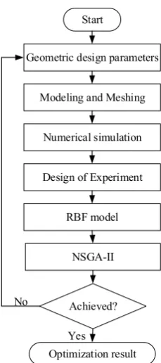
4.4. Optimization Design Strategy
Geometric design parameters
Achieved? No
Yes NSGA-II Design of Experiment
RBF model Modeling and Meshing
Numerical simulation
Optimization result Start
Figure 4. The flow chart of optimization design.
5. Results and Discussion
The optimization stage of the draft tube includes the 3D modeling, the CFD numerical simulations and the mathematical optimization, respectively. After the completion of the numerical calculation for the generated sampling points according to OLH method, we analyze the effect of the key geometrical parameters on the performance of the draft tube using the DOE module. The sensitivity relationship between the various geometric parameters of the draft tube is studied at the same boundary conditions. Figure 5 shows the Pareto chart of the geometrical parameters on the objective function of Cp and ζ.
0 10 20 30 40
Con
tr
ibu
ti
on
r
ate
/%
design parameter
h4 r1 L2 L1 r2 w h1 h3 d4
(a)
0 10 20 30 40 50
Contribut
ion r
ate
/%
design parameter
L2 r1 w h4 L1 r2 h1 h3 d4
(b)
Figure 5. Pareto chart for the objective function. (a) Pressure recovery factor; (b) Energy loss coefficient.
above the 9 input variables of sample data and the 2 output variable, the approximate model can be achieved using the RBF approximation, in which 125 sampling points are adopted as the training data sets and 15 sample points as testing data sets. In order to evaluate the accuracy of the approximate model, the error analysis and reliability test are performed. Table 3 shows the calculation results of the determination coefficient (R2) and the root mean square error (σ) with respect to the pressure recovery factor and the energy loss coefficient. The results indicate that the approximate model can be ensured adequately as the data used with R2 and σ (Table 3)
Table 3. Results of the response surface analysis.
Parameter R2 σ
Cp 0.943 0.954
ζ 0.071 0.06
The result obtained by CFD numerical simulation and the best lines fitted through RBF approximation are illustrated using the training and testing data sets as shown in Figure 6. Figure 7 shows the comparison of the calculation result for the objective function of Cp and ζ obtained by CFD numerical simulation and RBF approximation. As shown in Figure 6 and Figure 7, the approximate model has the high precision and reliability for the optimization design. Therefore, the validated approximate models are adopted to search for the optimal design variable in the design space.
0.68 0.70 0.72 0.74 0.76 0.78 0.80 0.82 0.66 0.68 0.70 0.72 0.74 0.76 0.78 0.80 0.82 Predicted value A ctual valu e
(a)
0.16 0.18 0.20 0.22 0.24 0.26 0.28 0.16 0.18 0.20 0.22 0.24 0.26 0.28 Predicted value A ctual value
(b)
Figure 6. Linear regression of the RBF for objective functions. (a) Pressure recovery factor; (b) Energy loss coefficient.
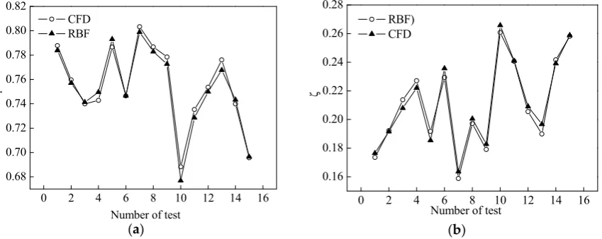
0 2 4 6 8 10 12 14 16 0.68 0.70 0.72 0.74 0.76 0.78 0.80 0.82 CFD RBF C p
Number of test (a)
0 2 4 6 8 10 12 14 16 0.16 0.18 0.20 0.22 0.24 0.26 0.28 RBF) CFD
Number of test
ζ
(b)
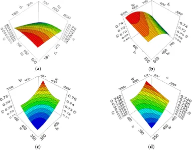
Figure 8 and Figure 9 show how the objective function varies with various geometric parameters of the draft tube. As shown in these Figures, we can know that the dimension variation of different geometric parameters affect on Cp and ζ.
(a) (b)
(c) (d)
Figure 8. The approximate model for each plot of two independent variables on the pressure recovery factor. (a) d4 versus h3; (b) h3 versus h1; h1 versus w; w versus r2..
(a) (b)
(c) (d)
Figure 9. The approximate model for each plot of two independent variables on the energy loss coefficient. (a) d4 versus h3; (b) h3 versus h1; h1 versus w;w versus r2
(a) (b)
Figure 10. The iteration process of optimization solution: (a) The pressure recovery factor; (b) The energy loss coefficient
The result comparison of the objective functions for the initial and optimal draft tube are listed in Table 4.
Table 4. The objective functions for initial and optimal draft tube.
Objective function Original type Optimal type
Cp 0.75 0.81
ζ 0.21 0.12
As shown in Table 4, the results indicated that the pressure recovery factor (Cp) increased from 0.75 to 0.81 and the energy loss coefficient (ζ) drastically reduces from 0.21 to 0.12.
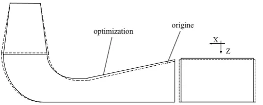
X Z
optimization origine
Figure 11. The shape comparison before and after optimization of draft tube.
Figure 11 and Figure 12 shows 2D and 3D model of the original and optimized model of the draft tube, respectively
(a) (b)
6. Conclusions
The multi–objective optimization for the performance improvement of the draft tube was performed using the combination of CFD, DOE, RBF and NSGA–II algorithm. The design strategy for the automatic optimization was performed by ISIGHT platform. We built the 3D model using the GAMBIT and carried out the performance calculations and analysis of the draft tube through CFD numerical calculation. The results of the numerical simulations based on the sample data generated by OLH method of the DOE technique were used to obtain the RBF approximation for improving efficiency of the calculation in the optimization process. Through the optimization process, the pressure recovery factor (Cp) increased from 0.75 to 0.81 and the energy loss coefficient (ζ) drastically reduced from 0.21 to 0.12. The presented methodology was very effective in solving the multi–objective problems with the low computational cost for the complex design. The comparison of the numerical calculation between the optimal and original geometric dimensions showed the superiority of the suggested optimization methodology. Therefore, the suggested optimization methodology can be applied for the performance improvement of the hydraulic turbine in the future.
Acknowledgments: This work is funded by National major scientific instruments and equipment development projects (2013YQ24042101).
Author Contributions: All the authors have contributed to this work. Mun Chol Nam has developed the idea presented in this work and carried out the numerical simulation and the optimization result analysis. Yue Xiang Ji, Kim Myong Il have devoted in research work for the numerical simulation and the optimization result analysis. The research work has been carried out under the guidance of Ba De Chun.
Conflicts of Interest: The authors declare no conflict of interest.
References
1. Soni, V.; Roghelia, A.; Desai, J.; Chauham, V. Design development of optimum draft tube for high head Francis turbine using CFD. International Conference on Fluid Mechanics and Fluid Power, IIT Madras, Chennai, India, December.2010, 16–18.
2. Khare, R.; Prasad, V.; Verma, M. Design Optimisation of conical draft tube of hydraulic turbine. IJAEST International Journal of Advances in Engineering, Science and Technology. 2012, 2(1), 22–26.
3. Prasad, V.; Khare, R.; Chincholikar, A. Hydraulic performance of elbow draft tube for different geometric configurations using CFD. IGHEM–2010, Ahec, IIT, Roorkee, India, October, 2010, 68–73.
4. Marjavaara, B. D.; Lundström, T. S. Redesign of a sharp heel draft tube by a validated CFD optimization.
International Journal for Numerical Methods in Fluids. 2006, 50(8), 911–924.
5. Nakamura, K.; Kurosawa, S. Design optimization of a high specific speed Francis turbine using multi–objective genetic algorithm. International Journal of Fluid Machinery & Systems. 2009, 2(2), 474–479. 6. Fares, R.; Chen, X.; Agarwal, R. Shape optimization of an axisymmetric diffuser and a 3D hydro–turbine
draft tube using a genetic algorithm. AIAA Aerospace Sciences Meeting including the New Horizons Forum and Aerospace Exposition. 2011,1243–1251.
7. Puente, L.; Reggio, M.; Guibault, F. Automatic shape optimization of a hydraulic turbine draft tube.
International Conference, CFD2003, Vancouver, BC. 2003, 28.
8. Eisinger, R.; Ruprecht, A. Automatic shape optimisation of hydro turbine components based on CFD. Task Quarterly. 2002, 6(1), 101–111.
9. Ruprecht, A.; Eisinger, R.; Göde, E. Innovative design environments for hydro turbine components.
HYDRO, Bern. 2000, 1–10.
10. Bonaiuti, D.; Zangeneh, M. On the coupling of inverse design and optimization techniques for the multiobjective, multipoint design of turbomachinery blades. Journal of Turbomachinery. 2009, 131(2), 021014–021029.
11. Mengistu, T.; Ghaly, W. Aerodynamic optimization of turbomachinery blades using evolutionary methods and ANN–based surrogate models. Optimization and Engineering. 2008, 9(3), 239-255.
13. Ali, O. M.; Mamat, R.; Najafi, G.; Yusaf, T. Optimization of biodiesel-diesel blended fuel properties and engine performance with ether additive using statistical analysis and response surface methods. Energies. 2015, 8(12), 14136-14150.
14. Gantasala, S.; Luneno, J. C.; Aidanpää, J. O. Investigating how an artificial neural network model can be used to detect added mass on a non-rotating beam using its natural frequencies: a possible application for wind turbine blade ice detection. Energies. 2017, 10(2), 184.
15. Tomoiagă, B.; Chindriş. M.; Sumper, A.; Andreu, A.S. Pareto optimal reconfiguration of power distribution systems using a genetic algorithm based on NSGA-II. Energies, 2013, 6(3), 1439-1455.
16. Xueyi, Q.; Huiping, M.; Guolai, Y.; Zeng, M. 3–D Modeling of hydraulic turbine draft tube based on Pro/E.
Transactions of the Chinese Society for Agricultural Machinery. 2009, 40(9), 103–106.
17. Menter, F. R. Two-equation eddy-viscosity turbulence models for engineering applications. Aiaa Journal. 2012, 32(8), 1598-1605.
18. Liefvendahl, M.; Stocki, R. A study on algorithms for optimization of Latin hypercubes. Journal of Statistical Planning & Inference. 2006, 136(9), 3231-3247.
19. Zhao, M.; Cui, W. C. Application of the optimal Latin hypercube design and radial basis function network to collaborative optimization. Journal of Marine Science & Application. 2007, 6(3), 24-32.
20. Elsayed, K.; Lacor, C. Modeling, analysis and optimization of aircyclones using artificial neural network, response surface methodology and CFD simulation approaches. Powder Technology. 2011, 212 (1), 115–133. 21. Wang, X. D.; Hirsch, C.; Kang, S.; Lacor, C. Multi-objective optimization of turbomachinery using
improved NSGA-II and approximation model. Computer Methods in Applied Mechanics & Engineering. 2011, 200(9), 883-895.
22. Deb, K.; Pratap, A.; Agarwal, S.; Meyarivan, T. A fast and elitist multiobjective genetic algorithm: NSGA-II. IEEE transactions on evolutionary computation. 2002, 6(2), 182-197.