ORIGINAL ARTICLE
Performance study about a new kind wood
fiber filter element utilized in capturing diesel
particulate material
Danfeng Du
1, Xiurong Guo
2*, Yuefeng Xu
2and Xiao Yang
2Abstract
A new kind diesel particulate filter (DPF) with gear-shaped wood fiber filter element is researched and it has very low cost and less requirement for fuel quality. In this paper, the mathematical models of the filtration resistance and the structural parameters of the wood fiber filter element were established first. Then by SEM, the advantages of this material can be proved. Finally, to verify reliability and efficiency of the filter elements with different structure param-eters, the filtration resistance change were compared and analyzed through a DPF bench test based on meeting the demand of filtration efficiency that is above 85%. The test results showed that the filtration efficiency is more than 85% and the filtration resistance is below 3 kPa. Meanwhile, the life span of this new kind wood fiber filter is more than 90 h and the cost of it is very low.
Keywords: Wood fiber filter, SEM, Filtration resistance, Diesel particulate filter, PM purification
© The Author(s) 2019. This article is distributed under the terms of the Creative Commons Attribution 4.0 International License (http://creat iveco mmons .org/licen ses/by/4.0/), which permits unrestricted use, distribution, and reproduction in any medium, provided you give appropriate credit to the original author(s) and the source, provide a link to the Creative Commons license, and indicate if changes were made.
Introduction
With the more and more serious problems of air pollu-tion, water pollupollu-tion, land desertification and persistent organic pollution, people are paying greater attention to environmental issues. Particularly, the particular matter (PM) 2.5, namely the particles in the atmosphere whose aerodynamics diameter is less than or equal to 2.5 μm, are rising in its concentration, thus leading to the fact that most parts of China have been frequently shrouded in fog and haze for the last few years [1]. Annual Report of China Vehicle Emission Control in 2013, released by Ministry of Environmental Protection at the beginning of 2014, showed that the diesel engine was one of the main sources of soot particles, and its particulate emissions added up to 602,000 tons, accounting for 90% of the total car emissions [2]. Therefore, the environmental problems caused by exhaust emissions from diesel vehicles should be extensively concerned.
Diesel particulate filters (DPFs) technology is one of the most effective methods for purifying PM emitted by diesel engines [3, 4], which has many advantages such as high collection efficiency, long life service and so on. So it has significant economic value and broad market prospects [5]. The filtration performance of the DPFs is primarily determined by its structure parameters and material properties. The existing filter elements of the DPFs are mostly solid cylinder shape and adopt cordier-ite, honeycomb ceramic or silicon carbide as the material. Although the DPFs have been used in many developed countries successfully, their spreading in developing countries is hampered mainly due to the high-quality fuel requirement and expensive price. To reduce the pollution of PM in many developing countries as soon as possible, a lot of innovative researches both on the material and the structure of the filter elements are extensively con-ducted. The wood fiber, as a kind of widespread porous materials in nature, has many virtues of high adsorption efficiency, low filtration resistance, less requirement for fuel quality, simple manufacturing procedure and very low price. The wood fiber DPF, combined with air cooling device, can be easily installed at the position of the tail pipe where the temperature is lower than other place of
Open Access
*Correspondence: [email protected]
2 Mechanical and Electrical Engineering Institute, Northeast Forestry University, Harbin 150040, Heilongjiang, China
the exhaust system [6]. Different structure, such as solid cylindrical and gear-shaped wood fiber filter has differ-ent structural stability and filtering ability. In this paper, the optimum structure parameters of a new kind of gear-shaped wood fiber filter element are studied by numerical simulation according to considering of two aspects: one is to increase the effective filtration area for improving the filtration efficiency; another is to reduce the filter fil-tration resistance and enhance the structural stability of the filter. Meanwhile, the simulation results are tested by experiments successfully based on meeting the demand of filtration efficiency that is above 85%.
Experiment and method
Structural design of the gear‑shaped wood fiber filter element
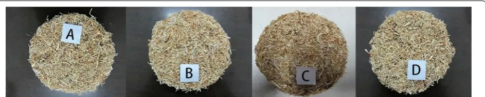
The structure of the filter element has great influence on the filtration efficiency, the exhaust back pressure and the service life. The design principle of the structure is that the filter element can be kept a state of structural stability and integrity under the instant impact of enormous back pressure and make the exhaust gas through it smoothly. Furthermore, the lower filtration resistance should be assured, which can improve engine performance and fuel economy and increase the durability of filter element in the whole service life. During our initial study work, by longitudinal cutting the Cunninghamia lanceolata and processing it into filamentous, we manufactured wood fiber that was dozens of microns thick, hundreds of microns wide, thousands of microns length. Using special pressing machine, micron wood fiber was made into four filter elements (Fig. 1), of which the packing density is 0.3 and the diameter is the same with the internal diameter of a detached DPF case (Fig. 2). We put these four filter elements into the detached DPF case in the order of A, B, C and D, in which the filter A is the nearest to the inlet of the DPF. After that, we installed the DPF in the exhaust system of a single-cylinder diesel engine named Lis-ter PetLis-ter AA1. When the engine worked for about 52 h under 50% load and 3000 r/min, the filtration efficiency of the DPF declined rapidly and Fig. 3 is the picture of the
filter elements taken out from the attached DPF case. As can be known from Fig. 3, the solid cylindrical filter ele-ments will be deformed and damaged unavoidably under the high intake velocity and back pressure, which makes them lose the trapping effect, and the damage of the filter element closer to the inlet end is more serious and can-not keep the integrity of the structure [7].
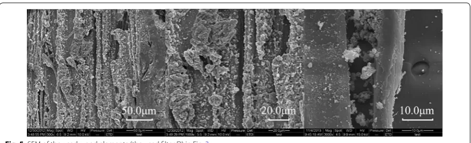
Wood fibers were extracted from the unused filter D in Fig. 1 for SEM and the result was shown in Fig. 4. Simi-larly, some wood fibers were taken out from the used fil-ter D in Fig. 3 for SEM and the result was shown in Fig. 5. The magnification of Figs. 4 and 5 are 500, 1000 and 3000 times from left to right, respectively. Through compari-son, it can be seen that there are a lot of micropores in wood fiber, which can make it not only good permeabil-ity, but also low back pressure, and can absorb a large amount of PM particles, so it is a very good filtering material.
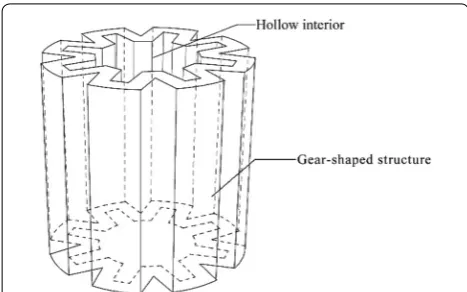
Since the solid cylindrical filter elements will be dam-aged by the impulse force of the exhaust gas when the back pressure is increasing instantly, a gear-shaped fil-ter element is designed under the condition of a certain structure size of DPF case, the height and the diameter of which are 150 mm and 140 mm, respectively. Figure 6 is the diagram of the gear-shaped wood fiber filter element with a hollow interior.
The assembly drawing of the filter element and the DPF case is shown in Fig. 7. When the diesel exhaust gas reaches the inlet of the device, an air deflector
Fig. 1 Wood fiber filter elements. A Is the nearest to the inlet of the DPF, B close to A, C close to B, and D is the nearest to the outlet of the DPF
guides the gas uniformly crossing the outer surface of the filter element, then into the hollow interior, and during this process the particles are collected and the exhaust gas is filtered. After that, the clean gas flows along the hollow interior and eventually out from the outlet of the DPF device. This structure design can increase the filtration surface area, reduce the filtra-tion resistance, improve the filtrafiltra-tion efficiency and prolong the service life of the filter element effectively.
Determination of optimum structure parameters of the gear‑shaped filter based on resistance
The gear-shaped wood filter mainly experiences the air-flow interference resistance caused by the gear-shaped structure and the airflow medium resistance caused by the porous wood fiber, respectively. The former is primarily affected by its structure parameters such as number of teeth, tooth thickness and nominal pressure Fig. 3 The used wood fiber elements. A Is the nearest to the inlet of the DPF, B close to A, C close to B, and D is the nearest to the outlet of the DPF
Fig. 4 SEM of the unused wood elements (the filter D) in Fig. 1
angle, and the latter by the intake velocity and the material properties of wood fiber.
The establishment of numerical model
In this study, the diameter and the height of the DPF case are 140 mm and 150 mm, respectively. To simplify the numerical model and simulate the airflow flowing through the filter, the following assumptions are given:
a. The exhaust gas is viewed as an incompressible fluid; b. The exhaust gas flows to the filter element uniformly; c. The exhaust gas flows through the filter without heat
exchange;
d. There is no deformation of filter in the filtering pro-cess;
e. Parameters of master gear are used when doing some data processing.
According to the proposed structure of Fig. 6, the numerical model is established as shown in Figs. 8 and 9.
According to the assumptions above and the range of the parameters in this research, the Reynolds number (Re) of this simulation can be worked out as follows [8]:
where ρ is the fluid density, V the average velocity of the fluid flowing through the medium, l the geometric char-acteristic size of the flow field, μ the kinematic viscosity of the fluid, A the cross-sectional area of flow, x the wet perimeter. Thus, the airflow in this simulation belongs to the laminar flow, which obeys Darcy’s equation and by it we can get:
where Q is the seepage discharge, ΔP the pressure differ-ence, A the filtering surface area, μ the fluid viscosity, and
Rm resistance of filtering media.
As seen from Eq. (1), the pressure difference is inversely proportional to the filtering surface area, and when other parameters are constant, the pressure difference increases with the decrease of the filtering surface area. Accordingly, the resistance of the filter element can be effectively reduced by increasing its filtering surface area.
Based on the assumptions above, the airflow should obey Darcy Laws [9], which is expressed as:
where ΔP is the pressure difference (Pa), L the thickness of the porous medium, μ the dynamic viscosity (Pa·s) of the fluid, K the permeability (m2), V is the average veloc-ity (m/s) of the fluid.
The permeability K was measured experimentally or calculated by the empirical formula [10] as follows:
where df is the diameter of the wood fibers, α packing density of the wood fibers.
(1)
Re= ρVl
µ =
4AρV
µx <2000
(2)
Q=(�P·A)(µ·Rm)
(3)
�P L =
µ KV
(4)
K = d
2 f
2.653α+39.34α2+144.5α3 Fig. 6 The gear-shaped wood fiber filter element with a hollow
interior
As was proposed in reference, the pressure loss caused by the filter medium can be expressed in Eq. (5) while the exhaust gas passes through the filter with a tilt angle.
(5)
�PM= µ ·L
K ·V·sinθ·
1+
K·ρ·V·sinθ· � 1
sin2θ −1 �
2µ·L
= µ ·L
K ·V·sinθ+ cos2θ
2 ·ρ·V 2
= µ·L·(2.653α+39.34α 2
+144.5α3) d2
f
·V·sinθ
+cos 2
θ 2 ·ρ·V
2
The teeth of the gear can be regarded as doubly folded structure, according to the research and analysis on the pleated filter conducted by Fu Haiming’s team [11], so the differential pressure of the filter caused by its struc-ture is determined by Eq. (6).
The overall pressure difference of the exhaust gas is the total of both the one generated by medium resist-ance and the other caused by its gear-shaped structure, namely:
Because of the master gear structure of the filter ele-ment, Eq. (8) and Eq. (9) can be obtained according to the model of Fig. 9 and the calculation formula of gear.
where the addendum coefficient ha* is 1 and the tip clear-ance coefficient c* is 0.25.
Deduced from Eq. (8) and Eq. (9), the tooth width
W and number of teeth Z can be given by Eq. (10) and Eq. (11):
Selection of model parameters
The diameter and the height of the DPF case in this paper are 140 mm and 150 mm. According to the assumptions,
(6)
�PG= �P ′ G ·ρV
2
�PG′ =
µ ρV ·
cos2θ·sinθ
L ·
1−
L h·sinθ
3 +
3µ ρV ·
cos2θ
tan2θ·
sinθ L · 1− L
h·sinθ + 1 2cos 2 θ 1+ 1 2cos 2 θ · 1− L
h·sinθ 2 + 1 4cos 4 θ· 1− L
h·sinθ 3 − 9 40cos 4 θ· 1− L
h·sinθ 4
(7)
P=PG+PM
(8)
h=ha+hf=(2h∗a+c
∗
)m
e= πm 2
ha=h∗am
(9)
W =2h·tanθ+W′
e=2ha·tanθ+W
′
Z= π (D− 2h)
W
(10)
W = πh+
5h·tanθ
4.5
(11)
Z =
4.5π(D−2h)
πh+5h·tanθ Fig. 8 The cross section of the gear-shaped filter model
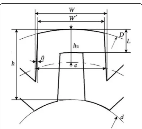
Fig. 9 The tooth structure of the gear-shaped filter; where h is the tooth height, ha the addendum, W the tooth thickness, L the thickness of filter, θ nominal pressure angle, Z the number of teeth, d
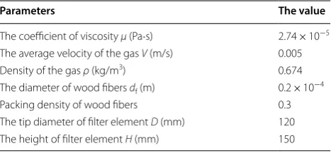
the gas is at steady state of incompressibility. As the emission temperature of most tail pipe where the DPF researched in this paper is installed usually ranges from 70 to 273 °C [12], the coefficient of viscosity μ and the density ρ of the exhaust gas can be obtained by referring to the table in reference that shows how the two param-eters changes with temperature. Furthermore, some specific parameters of the numerical model are given in Table 1.
The effects of structural parameters on the resistance of filter element
According to the national standards, the filtration resistance of the DPF used widely in the developed countries is no more than 20 kPa. However, based on extensive PM filtration experiments of wood fiber DPF, it is known that when the filtering performance decreased obviously and the filter element reaches its longest service life, its maximum pressure drop is only about 3 kPa. Therefore, in this study, the largest fil-tration resistance allowed is 3 kPa. Furthermore, it is
assumed that the amount of exhaust passing through the DPF is certain and the other structural parameters of the filter are constant. Then the values in Table 1 are introduced into Eq. (7) and input to MATLAB 7.11.0, and the Fig. 10a, b can be obtained. When the tooth height of the filter is 30 mm, and the thickness, respec-tively, takes the values of 6 mm, 8 mm and 10 mm, the curve of the filtration resistance changing with nominal pressure angle is shown in Fig. 10a. When the thickness of the filter is 10 mm and the filter tooth height took the values of 20 mm, 30 mm, and 40 mm, respectively, the curve of the filtration resistance changing with the nominal pressure angle is shown in Fig. 10b. As seen from Fig. 10a, b, when the nominal pressure angle is less than 6°, the filtration resistance increases as the angle is reduced, and when nominal pressure angle ranges from 3° to 6°, the filtration resistance can reach a minimum. Furthermore, when the angle is greater than 6°, the filtration resistance will increase with the angle increasing. So it is proposed that the gear-shaped filter element should have its optimal nominal pressure angle within 3° to 6°, and the final choice of the simulation value in this paper is 5°.
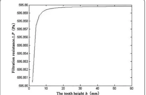
With the filter element’s nominal pressure angle being 5° and the other structure parameters being constant, substituting values in Table 1 into Eq. (7) and input-ting relative data to MATLAB7.11.0, the curve of the filtration resistance changing with the height of tooth can be obtained (Fig. 11). As seen from Fig. 11, when the nominal pressure angle is constant and the tooth height is more than about 10 mm, the resistance raises slightly with the increase of the tooth height, which can be negligible due to the small influence. As well Table 1 Parameters of the model
Parameters The value
The coefficient of viscosity μ (Pa·s) 2.74 × 10⁻⁵
The average velocity of the gas V (m/s) 0.005
Density of the gas ρ (kg/m3) 0.674
The diameter of wood fibers df (m) 0.2 × 10⁻⁴
Packing density of wood fibers 0.3
The tip diameter of filter element D (mm) 120
The height of filter element H (mm) 150
known that the filtration efficiency can be improved by increasing the tooth height of the filter as filtering area is enlarged effectively. But the tooth height cannot be too high for the limited size of DPF. So the tooth height can be increased within a reasonable range of 10 mm to 30 mm recommended, and its value is 30 mm in the simulation of this paper.
When the filter element’s nominal pressure angle is 5°, the tooth height is 30 mm, and the other structural parameters remain constant, substituting the values in Table 1 into Eq. (7) and inputting data into MATLAB 7.11.0, the curve of the thickness of the filter changing with resistance can be obtained (Fig. 12). As shown in Fig. 12, the filtration resistance rises with the increas-ing of the thickness of the filter, and when the thick-ness is greater than 7 mm the growth trend becomes much more obvious. Therefore, the optimal range of the thickness should be L ≤ 7 mm, and the choice of the value in this simulation is 7 mm.
Since the tooth height (h = 30 mm), the nominal pressure angle (θ = 5°) and the thickness of the filter (L = 7 mm) are introduced into Eqs. (10) and (11), the tooth thickness (W = 23.93 mm) and number of teeth (Z = 8) can be obtained.
With various factors such as the material utilization, the size of DPF, stability of the structure and complex-ity of processing technique considered, it is proposed by numerical simulation analysis that the structural parameters of the gear-shaped wood fiber filter are the nominal pressure angle θ = 5°, tooth height h = 30 mm, the thickness of the filter L = 7 mm, the tooth thickness
W = 23.93 mm and the number of teeth Z= 8. The design of DPF bench test
To test the resistance pressure and the filtration efficiency of the gear-shaped wood fiber filter elements, a DPF test
bench was designed based on some relevant require-ments in this paper. The test devices mainly involved a single-cylinder diesel engine named Lister Petter AA1 (as shown in Table 2), a detachable DPF case, a smoke opaci-meter (NHT-6, China), a exhaust gas analyzer (NHA-500, China), some various types of sensors, muffler and com-puter equipment, etc. The overall structure of the test devices can be seen in Fig. 13.
The working condition of the DPF testing was as fol-lows: atmospheric pressure is 101.3 kPa, the indoor tem-perature 20 °C, the relative air humidity 50% ± 15% and the working condition is 50% load and 3000 r/min. The structure parameters of the filters were listed in Table 3. When manufacturing the filter elements, besides the wood fibers, some additional additives or adhesives such as glass fiber and phenolic resins were added, whose influence on the experimental data were neglected. The picture of the gear-shaped filter elements are shown in Fig. 14.
Fig. 11 The tooth height changes with pressure
Fig. 12 The thickness of the filter changes with pressure
Table 2 Technical parameters of diesel engine Lister Petter AA1
Items Parameters
Engine type
Single-cyl-inder, four stroke
Cylinder 69.85 mm
Engine displacement 0.22 L
Rated speed 3600 r/min
Lubricant consumption ratio 0.015 L/h
Displacement 57.15 mm
Compression ratio 17:1
Maximum power 2.63 kW
Results and discussion
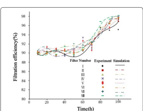
First, we manufactured 8 gear-shaped filter elements according to the structural parameters shown in Table 2. Then we chose one of the filter elements and put it into the detachable DPF case. Finally, the wood fiber DPF was installed in the DPF test bench and the experiment was started. Before recording data and analyzing the proper-ties of the wood fiber DPF, the engine was maintained to run steadily for about 10 min to ensure that the remain-ing exhaust gas in the pipe was evacuated and the engine worked stably. During the test, the values of the filtration resistance and the filtration efficiency were recorded at different times and when both of them rose sharply, the engine was turned off and then the used filter element was substituted by the next one until the eight filter ele-ments from NO. I to NO. VIII listed in Table 2 were all tested. In this research, the total testing time for each fil-ter element is around 95 h and the filtration efficiency of all the filter elements is more than 85%, which is satisfied with the application requirement. The test results of the
filtration resistance and filtration efficiency are shown in Figs. 15 and 16.
As seen from Fig. 15, the filtration performance of the filter elements of NO. V, VI and VII are significantly bet-ter than that of the others, among which the performance of NO. V is the best. Compared to the other filters with different structural parameters, NO. V has less filtration resistance, lower growth rate of back pressure, more sta-ble structure and longer service life. Furthermore, when the structural parameters of the gear-shaped wood fiber filter elements are kept in the optimum range obtained from this study, the filters have better filtration perfor-mance and the difference between them is very slight. However, when the structural parameters of the filters are outside the range of optimum values, the filtration performance will decrease obviously. Thus, the optimality of structural parameters for the gear-shaped wood fiber filter has been proved. Furthermore, from Fig. 16, we can see the filtration efficiency of all filters is more than 85%, which means they all can meet with the demand of national standards. Meanwhile, as known from above research, there might be some filtration resistance errors between the results obtained from experiments and the numerical simulations mainly because the numerical model developed under the premise of ideal conditions, and some factors such as the media properties, uneven-ness of filter material, and the instability of air speed would cause some deviations of the data. In summary, the structure parameters of the gear-shaped wood fiber filter element, obtained by establishing the numerical model, are feasible and effective. Compared with tradi-tional filter element whose material is cordierite, honey-comb ceramic or silicon carbide, etc., the tooth-shaped wood fiber filter has obvious advantages. According to Ref. [13], the traditional DPFs have back pressure ranging from 2 to 20 kPa, which seriously affects the engine per-formance. However, for wood fiber filter, a high poros-ity volume may definitely reduce the pressure drop, so its back pressure only ranging from 300 to 3000 Pa. In Fig. 13 The overall structure of the DPF test bench
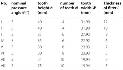
Table 3 The structural parameters of the filter element No. nominal
pressure angle θ (°)
tooth height h
(mm)
number
of teeth N tooth width W
(mm)
Thickness of filter L
(mm)
I 5 40 4 31.90 12
II 5 40 4 31.90 10
III 5 35 6 27.92 8
IV 5 35 6 27.92 6
V 5 30 8 23.93 7
VI 5 30 8 23.93 5
VII 5 25 10 19.94 7
VIII 5 25 10 19.94 5
terms of filtration efficiency, the traditional filter element and wood fiber filter element can all meet the require-ments of national standards. Because of the large poros-ity, the wood fiber filter has huge dust capacity and long service life and after use it can be replaced directly and the replaced filter can be recycled easily, whereas the traditional filter element needs to be regenerated, which greatly increases the running cost of DPF. Therefore, the tooth-shaped wood fiber filter has a broader application prospects.
Conclusions
The gear-shaped wood fiber filter has very low cost and less requirement for fuel quality, and it can be changed easily after about 6000 km trip when automobile mainte-nance. The replaced filter element can be used as fuel or
fertilizer. According to our experiments, the filters with optimum structural parameters obtained by numerical simulation have better properties. The conclusions as follows:
1. To increase the filtration area and reduce filtration resistance, a gear-shaped wood fiber filter element is developed whose filtration resistance is smaller, fil-tration area larger and the work efficiency higher. 2. The theoretical equation of filtration resistance with
the tooth height h, nominal pressure angle θ and the thickness of the filter element L were deduced by establishing structural parameter model referring to existing researches and empirical formulas; the opti-mal tooth height h, the nominal pressure angle θ and the thickness of the filter element L were obtained by MATLAB analysis. Furthermore, the tooth thick-ness W and number of teeth Z were worked out with some relevant formulas.
3. The optimal structural parameters of the gear-shaped filter elements are obtained by numerical simula-tion as: h = 30 mm, θ = 5°, L = 7 mm, W = 23.93 mm, Z = 8, respectively, the reliability and efficiency of which were verified by the comparison and analysis of the results from the DPF bench tests.
Abbreviations
DPF: diesel particulate filter; SEM: scanning electron microscope; PM: particular matter; Re: reynolds number.
Authors’ contributions
Conceived and designed the experiments: DD. Writing manuscripts: DD, XG. Performed the experiments: XG. Analyzed the data and set type: YX. Contrib-uted instrument/materials/tools: XY. All authors read and approved the final manuscript.
Author details
1 Transportation College, Northeast Forestry University, Harbin 150040, Hei-longjiang, China. 2 Mechanical and Electrical Engineering Institute, Northeast Forestry University, Harbin 150040, Heilongjiang, China.
Acknowledgements
This paper is supported by the National Natural Science Foundation of China (Grant: 31470611); the Fundamental Research Funds for the Central Universi-ties (Grant: 2572017 EB04); Heilongjiang province returnees science fund (LC2017019).
Competing interests
The authors declare that they have no competing interests.
Availability of data and materials
We declared that materials described in the manuscript, including all relevant raw data, will be freely available to any scientist wishing to use them for non-commercial purposes, without breaching participant confidentiality.
Funding
This study was funded by National Natural Science Foundation of China (Grant Number: 31470611), the Fundamental Research Funds for the Central Universi-ties (Grant Number: 2572017EB04), Heilongjiang province returnees science fund (LC2017019).
Fig. 15 The filtration resistance of gear-shaped wood fiber filter as a function of the time
Publisher’s Note
Springer Nature remains neutral with regard to jurisdictional claims in pub-lished maps and institutional affiliations.
Received: 24 October 2018 Accepted: 27 February 2019
References
1. Zhang NN, Ma F, Qin CB, Li YF (2018) Spatiotemporal trends in PM2.5 lev-els from 2013 to 2017 and regional demarcations for joint prevention and control of atmospheric pollution in China. Chemosphere 210:1176–1184 2. Chen C, Li H, Deng CL (2010) The change of the density of air viscosity
with temperature table. Intern Combust Eng Power Plant 12(6):8–9 3. Zheng Y, Harold MP, Luss D (2014) Optimization of LNT-SCR dual-layer
catalysts for diesel NOx emission control. SAE Tech Paper 7(3):1280–1289 4. Zheng Y, Liu Y, Harold MP, Luss D (2014) LNT-SCR dual-layer
cata-lysts optimized for lean NOx reduction by H2 and CO. Appl Catal B 148–149:311–321
5. Pan BF, Wang W, Wang RB (2013) Analysis on the Construct of Fine Particle Monitoring Network and Monitoring Technique System in China. Environ Sustain Dev 38(3):9–13 (in Chinese)
6. Guo XR, Du DF, Wang FH (2011) Study on test instrument and filtra-tion theory of the carbonized micron wood fiber DPF. Microporous Mesoporous Mater 142:655–660
7. Zha WJ, Qian FP (2013) Optimization of Structural Parameters for the Pleated Filter Element of Cartridge Filters by Response Surface Meth-odology Based on the Resistance. Chin J Process Eng 13(5):771–775 (in Chinese)
8. Hang K (2013) Reassessing Darcy’s law on water flow in porous media. Earth Sci J China Univ Geosci 38(06):1327–1330 (in Chinese)
9. Kasper G (2014) Structure and density deposits formed on fibers inertial particle deposition and bounce. J Aerosol Sci 41(12):1167–1182 10. Rao N, Faghri M (1988) Computer modeling of aerosol filtration by fibrous
filters. Aerosol Sci Technol 8(2):133–156
11. Fu HM, Xu F, Jin RF (2010) Relationship of filtration resistance with geom-etry parameters across pleated aerosol filter. J Huaqiao Univ (Natural Science) 31(3):307–312 (in Chinese)
12. Zhang A (2003) Study on the relativity of hot load of marine diesel engine and its exhaust temperature. J Wuhan Inst Shipbuild Technol 4:13–16 (in Chinese)