Ionut Daniel Geonea and Daniela Tarnita
Faculty of Mechanics, University of Craiova, Craiova, 200512, Romania
Correspondence to:Daniela Tarnita ([email protected])
Received: 19 March 2017 – Revised: 1 September 2017 – Accepted: 8 September 2017 – Published: 17 October 2017
Abstract. This work addresses the design and numerical characterization of a new exoskeleton solution for human leg motion assistance and rehabilitation. The exoskeleton solution is anthropomorphic, simple, low cost and easy to adapt on the human subject. The design aspect concerns the exoskeleton mechatronic structure, achieved in SolidWorks virtual environment. Numerical simulation is performed in MSC.ADAMS simulation environment. Obtained results for the exoskeleton computed motion are compared with those obtained from experimental walking of healthy subject. The prototype feasibility is studied both for design and operation aspect.
1 Introduction
Nowadays, the importance of measuring and analyzing gait variability has increased and it is more and more recog-nized and used in biomechanics, in robotics, in rehabilita-tion and in clinical research field. Clinical gait analysis usu-ally consists of measurement of gait parameters, kinematic analysis, kinetic measurement and electromyography. Spa-tial and temporal parameters of gait provide useful diagnos-tic and therapeudiagnos-tic information, if they are accurately mea-sured (Begg et al., 1989). The most analyzed parameters of normal and pathological human gait are the following: trav-elled distances, velocity, gait phases, step length, joints an-gles, swing time, support time, ground reaction forces, forces and momentum in joints (Tarnita, 2016). In the medical field, the knowledge of gait characteristics, the monitoring and evaluating changes in human gait reveal important informa-tion about quantitative objective measurement of the differ-ent gait parameters, about the evolution and early diagnosis of different diseases and about physical therapy, involving rehabilitation, which helps to improve the walking function (Sutherland et al., 2002; Tao et al., 2012; Muro-de-la-Herran et al., 2014). The main goal of the rehabilitation therapy is to minimize functional deficits of disabled patients, this pro-cedure requiring a repetitive motion performed by the pa-tient. For that purpose, the modern rehabilitation techniques use mechanical systems (as robots or exoskeletons) to as-sist the lower limbs in their movements’ rehabilitation. The
main advantages of robotic rehabilitation are: reducing de-pendence on clinical staff, providing adequate rehabilitation movements and adjusting the level of treatment according to patient requirements, allowing control of joint movement, helping ensure controlled repetitive preparation at a reason-able cost (Banala et al., 2007).
An exoskeleton is defined as an active mechanical device that is essentially anthropomorphic, in nature is “worn” by an operator and it augments the performance of an able-bodied wearer (Dollar et al., 2008). This purpose is realized by pro-viding a supplementary force to the legs (Viteckova et al., 2013). Due to the increased interest upon the development of rehabilitation procedures based on mechatronic and robotic technologies, in recent years, many review studies which evaluate the progress and future directions in rehabilitation, were published (Onose et al., 2013; Young et al., 2017; Chen et al., 2013; Lajeunesse et al., 2016 and Louie et al., 2016). Ones of the most popular exoskeletons are:
– BLEEX (Berkely Lower Extremity Exoskeleton), pointed as the first load carrying exoskeleton (Anama et al., 2012). BLEEX exoskeleton actuates the hip abduc-tion/adduction, hip flexion/extension and knee flexion;
tem, the patients that are affected by spinal cord injuries are sustained by a body weight support (Hesse et al., 2003).
– REX exoskeleton by REX Bionics is a wearable ex-oskeleton capable to support the weight of the patient and is able to self-balance (Barbareschi et al., 2015).
Multi joint exoskeletons are described by Tingfang et al. (2015), and most of them are based on the principle of predefined gait trajectory control. This principle according to which the exoskeleton replicates the desired joint trajec-tory corresponding to an experimental data set acquired from a healthy person is implemented to exoskeletons like HAL, Rewalk and Mindwalker (Wang et al., 2015a).
Exoskeletons for industrial application are presented in de Looze et al. (2016), powered exoskeletons in post – stroke rehabilitation are studied in Louie et al. (2016) and for arm rehabilitation in Schorsch et al. (2014); Jarrassé et al. (2014). The aspect of control systems of active exoskeletons is stud-ied in Anama et al. (2012), while aspects of exoskeleton de-sign, path planning, modeling and simulation, experimen-tal tests are studied by Carbone et al. (2007); Ashkani et al. (2016); Wang et al. (2015b); Ceccarelli et al. (2009).
Recently, numerous review articles presenting the state of the art concerning passive devices used for rehabilitation of lower limb are published. These types of device are repre-sented by passive functional upper-limb orthoses (Rahman et al., 2006).
According to the rehabilitation principle (Díaz et al., 2011), the active rehabilitation devices can be grouped in five groups: (a) treadmill gait trainers; (b) foot-plate-based gait trainers; (c) mobile robotics based solutions; (d) stationary gait trainers; (e) ankle rehabilitation systems, as active foot orthoses.
Some studies (Onose et al., 2016) evaluate the progress and future directions in the field of robotic rehabilitation technologies, from the perspective of professionals, engi-neers and users, while the main improvements needed for the development and functional optimization of practical ex-oskeletons are highlighted in Lajeunesse et al. (2016).
Another research theme from this subject area is the de-velopment and evaluation of a new leg robotic exoskeleton, called H2, intended for gait rehabilitation of the stroke sur-vivors (Bortole et al., 2015). In order to guide the develop-ment of lower limb exoskeletons, some studies (Kao et al., 2010) had, as purpose, the understanding of how humans adapt to powered assistance.
bilitation (Rahman et al., 2006). A category of exoskeletons is intended to a single joint motion assistance (Ceccarelli et al., 2016), and other category assists the motion of two or more leg joints. Exoskeletons in this category use actuators for joints, command and control architectures, and are costly solutions that are difficult to deploy on a large scale (Geonea et al., 2013). As a conclusion these existing solutions are not accessible to disabled persons, although they assure proper requirements for rehabilitation.
The low-cost solution does not perform rehabilitation movements for all of the leg joints because they generally provide active rehabilitation movement only for the hip and knee joints. Other devices are used as passive solutions to provide rehabilitation movements that correspond to a spe-cific rehabilitation therapy designed to recover walking for a particular joint such as the hip, knee or ankle. Several de-vices solutions are designed to reproduce human bipedal lo-comotion, but generally few of them provide approximately anthropomorphic movements (Geonea et al., 2015).
This research proposes a new leg exoskeleton design that provides support for the movement of the hip and knee joints. An experimental human walking test is used to obtain ref-erence movement laws for the exoskeleton’s joints during walking. Then, a dynamic study of the walking exoskeleton attached to a human virtual mannequin is performed. The dynamic virtual model is designed using SolidWorks, and numerical simulation is done using the MSC.ADAMS soft-ware. A prototype of the exoskeleton is manufactured and subjected to experimental tests. Finally, a comparison of mo-tion laws performed by a healthy human subject and by the mannequin-exoskeleton assembly is made.
2 Human gait experimental analysis
Human gait analysis represents a large interest subject in the literature (Varela et al., 2015). Also experimental characteri-zation of human falling down, represent a subject presented in recent studies (Meng et al., 2017). According to some studies (Winter et al., 1979; Tarnita et al., 2013), human gait represents a cyclic motion between heel strike on ground and next ground contact of same heel. This cycle consists of two important phases, stance phase and swing phase. Intermedi-ate phases are also studied, a complete gait cycle phases be-ing described by Perry et al. (2010).
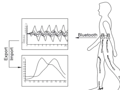
ro-Figure 1.Goniometers and Datalog devices mounted on the human subject, during the test.
bust, lightweight and flexible, these sensors can be worn by subjects without alteration of the movement of the joint. Twin axis goniometers SG series are used to measure joint angles simultaneously in two planes of movement. For ex-ample, to measure knee movement, the end blocks of the goniometer are attached on the subject using double sided tape. The goniometer has two separate output connectors, one of them is used to measure knee flexion/extension an-gle and the other connector measures valgus/varus anan-gle. For this research the measurement of flexion-extension an-gles in sagittal plane presents interest. In Fig. 1, the ac-quisition system composed by Biometrics software installed on the notebook, by electrogoniometers sensors and by the Datalog devices mounted on the human subject, is shown. The sensors are connected to Biometrics DataLog equip-ment through which the data are transferred to the computer via Bluetooth interface. Measurement frequency is specified to 500 data registration/second. The measurement accuracy of the goniometers is±2◦ measured over a range of±90◦ and the repeatability is 1◦, measured over a range of 90◦ (http://www.biometricsltd.com/gonio.htm).
The block schema of the acquisition system is shown in Fig. 2.
Experimental data acquired from a 35 years old healthy subject for normal walking during 30 s are reported as angle variation in time, for the ankle, knee and hip joints, in sagittal plane, for the right leg (Fig. 3) and for the left leg (Fig. 4). Experimental tests performed by the male subject consist in 25 consecutive gait cycles repeated for five times in the same walking conditions.
The anthropometric data of the human subject are: body weight=700 N, height=1.67 m, hip-knee length=0.42 m, knee-ankle length=0.39 m, ankle-little toe=0.18 m. The healthy subject was pain-free and had no evidence or known history of motor and skeletal disorders or record of surgery to the lower limbs. The study was approved by the Ethics Com-mittee of Human Research, University of Craiova, Romania.
Figure 2.Block schema of the acquisition system.
Figure 3. 1 – right knee flexion/extension; 2 – right hip flex-ion/extension; 3 – right ankle flexflex-ion/extension; Healthy human measured hip, knee and ankle joint angle, in sagittal plane, for right leg.
The knee joint angular maximum amplitude is by 65◦ (Figs. 3–4) and for the hip joint the maximum amplitude is by 40◦(Figs. 3–4). These results are useful in order to make a comparison between achieved joints angles of human sub-ject and joints angles achieved by the exoskeleton. Accord-ing to Zoss et al. (2005), for human walkAccord-ing the hip flexion reaches a maximum value of 32.2◦and for knee 73.5◦. Gait outputs of joint angles are presented by Lu et al. (2012). Re-sults presented reveal that for healthy subject the hip flex-ion/extension varies between [−15, 25◦] and for the knee is comprised in the interval [5, 65◦]. As a conclusion, hu-man gait outputs presents variability from one subject to an-other. The results obtained in this research, for the human hip and knee joint flexion-extension angles, are comparable with those presented by other researchers in their studies.
Figure 4. 1 – left knee flexion/extension; 2 – left hip flex-ion/extension; 3 – left ankle flexflex-ion/extension; Healthy human mea-sured hip, knee and ankle joint angle, in sagittal plane, for left leg.
Figure 5.1 – knee flexion/extension; 2 – hip flexion/extension; 3 – ankle flexion/extension; The experimental angles variations for dis-abled human, in sagittal plane, for right leg.
from the healthy right joint to the osteoarthritic left knee joint. As we can see in Fig. 6, the maximum amplitude of flexion-extension cycles of OA knee is about 47◦ and it is lower than the maximum amplitude of the unaffected right knee which is about 52◦. The variation in time of the os-teoarthritic knee angle (Fig. 6) is different from those of an-gle of the healthy right joint (Fig. 5), the patient dragging the disabled leg.
Human gait variability from one cycle to another for the same subject, from one subject to another and from one healthy subject to a diseased one, imposes the normalization of gait cycles. Normalization is done using SimiMotion soft-ware where the data files are transferred (Tarnita et al., 2017). For the accuracy of the final results, there were eliminated 2 cycles from the beginning and from end of data files. To com-pare results, it is necessary to determine the average cycle for each acquired data file.
3 A new leg mechanism design
Taking into account existing solutions of leg mechanisms used for human leg motion assistance and rehabilitation, pre-sented in reviews and research studies, (Dollar et al., 2008; Rajesh et al., 2013; Bruzzone et al., 2012; Dumitru et al., 2015; Copilusi et al., 2015), for this research a single DOF, simple and light solution of a mechanism which assists the human gait is developed. There are developed similar one DOF leg solutions at LARM Laboratory Casino, Italy (Li et al., 2013; Wang et al., 2015b).
Figure 6.1 – knee flexion/extension; 2 – hip flexion/extension; 3 – ankle flexion/extension; The experimental angles variations for dis-abled human, in sagittal plane, for left leg (disdis-abled leg).
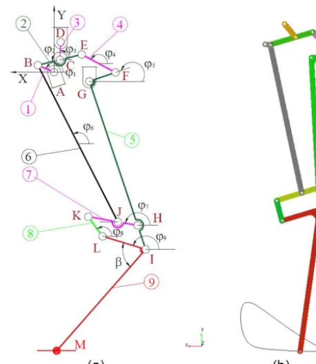
Figure 7.Leg exoskeleton:(a)a kinematic scheme;(b)virtual sim-ulation model of leg exoskeleton.
The starting point in developing of a new leg mechanism is that the ankle joint trajectory must assure an ovoid path, to assure human leg motion during swing and also to assure proper angular variations of the joints. The proposed struc-tural solution is optimized from kinematic perspective, using virtual modeling and simulation methods and principles (Il-hem et al., 2013; Carbone et al., 2007) and path planning (Carbone et al., 2008; Tedeschi et al., 2015). The optimal de-sign solution is materialized into an experimental prototype. The mechanical solution is completed with the command and control architecture. For actuation a DC gear motor is used. The motor speed is controlled with a hardware architecture based on pulse wave modulation method (PWM).
Figure 8.A virtual model of the exoskeleton in SolidWorks:(a) iso-metric view;(b)upper part detail view.
two orthogonal segments: FG and IG. Joint G, representing the hip, is connected to the upper frame, considered as a fixed element.
The link 4 transmits the motion, being connected by joint E to Chebyshev linkage, and by joint F to femur segment. Joint B is a multiple one, here being connected links 1 and 2 and link 6 with 1. Through link 6 and the quadrilateral link-age ILKH the motion is transmitted from link 1 to the link 9 (materialized by exoskeleton tibia). Based on this innova-tive structure of the rehabilitation exoskeleton, a 3-D model is designed as it is presented in Fig. 8.
In order to synthesize the lengths of the mechanism links we started from the patient dimensions (femur and tibia). The trajectory of ankle joint is tracked by performing 2-D simulations in MSC.A2-DAMS (Wojtyra et al., 2003). Us-ing ADAMS “Design of experiments”feature, a preliminary prototype optimization, using as constrains the femur and tibia lengths and the imposed hip and knee angular varia-tion, is performed. For this case the mechanism operation is being carried on a supporting stand without contact with the ground. In this case, the design variables are the mecha-nism joints coordinates’ variations. This innovative structure allows the leg exoskeleton to executes an ovoid path of the ankle joint M, (Fig. 9b), when it performs in stationary mode (the upper frame is fixed and the exoskeleton leg has not con-tact with ground), and it also allows proper variations of the angular amplitudes for the hip and knee joints noted G and I, similar values with the experimental results presented in Figs. 3–4. Can be noticed in Fig. 7, that the ankle joint for this solution is not considered as an active one, the joint M being modeled as a rotational spring damper. As in case of other powered exoskeletons, the ankle joint is not actuated. The link (9) is connected with the exoskeleton foot (10), by a rotational joint M. For the torsional spring are specified the rigidity and damping coefficients used to design the dynamic model of the exoskeleton.
Figure 9.Mechanism for exoskeleton leg:(a)design parameters; (b)computed foot trajectory.
A virtual model of the exoskeleton assembly, consisting of two legs attached to an upper frame and of one chain trans-mission for both legs actuation, is designed in SolidWorks in order to perform a dynamic simulation. The links 1 of left and right legs are opposite positioned to 180◦taking into ac-count the gait phases. In Fig. 8 is presented the exoskeleton assembly, comprising all of its components, according to the kinematic scheme presented in Fig. 7.
The proposed exoskeleton mechanism is characterized by some novel characteristics:
Comparing with other rehabilitation exoskeletons, the present proposed design has only one actuator. For that rea-son, it’s a low-cost design solution and simple operation, be-cause don’t needs a complex command and control hardware. The design solution can generate a suitable gait by its con-struction and gait planning is not necessary. By using a par-allelogram in the knee joint, the foot moves parallel to the ground during propelling phase (as see in Fig. 9b, where is presented the computed ADAMS trajectory). Being a low-cost solution, the ankle joint is not actuated, but a torsion spring is mounted in order to be used for simulation.
It has an anthropomorphic structure, because the achieved joint motion of the exoskeleton is comparable with those of human subjects. A detailed comparison is presented in the paper.
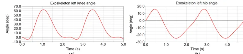
Figure 10.Computed joints angle variation:(a)knee joint;(b)hip joint.
Figure 11.Computed plot of ankle joint M position:(a)uponx;(b)uponyaxis.
Figure 12.Computed plot of ankle joint M velocity:(a)uponx;(b)yaxis.
Figure 13.Computed plot of ankle joint M acceleration:(a)uponxaxis;(b)uponyaxis.
4 Kinematics of exoskeleton leg mechanism
In order to evaluate the prototype leg characteristics, a kine-matic analysis considering the mechanism operation on a supporting stand is performed. The reference coordinate sys-tem XY has its origin placed in joint A. The design pa-rameters of the leg mechanism are indicated in Fig. 9. The lengths of the mechanism elements and the coordinates of fixed joints A, D, G are shown in Table 1.
For a proper dimensional synthesis of the mechanism, the virtual simulation tools available in Solid Works software are
nequin:(a)right leg view;(b)left leg back view.
link AB is designed with a minimum dimension of 12 mm in the first phase for minimum power requirements and in final design with length of 13.5 mm, in order to increase the knee and hip joints angular amplitude motion. Link BJ is designed with 355 mm, because, in initial position, the segments GI and IM have to be a straight line, as the human leg in vertical position. Linkage IHKL is designed as a quadrilateral mech-anism. Finally, the lengths of links 2, 3 and 4 are adjusted in SolidWorks parametric design, following to obtain an ovoid trajectory of the point M resulted by virtual simulation track-ing.
The kinematics of the mechanism is described by the loop closure Eq. (1).
lAB+lBC+lCD+lAD=0;lBE+lEF+lFG+lBG=0
lGH+lHJ+lJG=0;lKH+lHI+lIL+lKL=0
(1)
Detailed equations of mechanism kinematics are presented in Appendix A.
The mathematical model characterizes the kinematics of the leg exoskeleton when it operates on a supporting stand. This kinematical model is solved in Maple software, and it is useful in order to validate the engineering feasibility of the proposed leg mechanism. Numerical results of the mathemat-ical model are reported in plots in Figs. 10–13. In Fig. 10a, the computed variation of the knee angle is shown, and in Fig. 10b the computed variation of the hip angle is presented. By comparing the obtained motion laws with those obtained in experimental gait analysis, for the healthy subject, pre-sented in Figs. 3–4, one can remark that the variation in time is almost similar. The numerical angular amplitude for the knee joint varies in the interval [−4, 64◦] with a maximum value equal to 68◦, comparable to 65◦, value obtained in the experimental gait analysis, presented in Figs. 3, 4. In the case of hip joint, the numerical angular amplitude varies in the in-terval [−25, 16◦] with a maximum amplitude equal to 41◦. Also, the hip angular amplitude is close by 40◦, similar with the one obtained for the human hip joint.
The leg exoskeleton realizes a displacement of 220 mm, from−180 to 40 mm, along horizontalxaxis, corresponding
The walking velocities on x and y axes for the M joint range in the interval [−320; 380] mm s−1, respec-tively, in the interval [−180; 230] mm s−1, as shown in Fig. 12, while, the computed acceleration onx andy axes of the M joint, presented in Fig. 13, varies in the interval [−1115; 1105] mm s−1, respectively, in the interval [−1115; 700] mm s−2.
5 Modeling and simulation
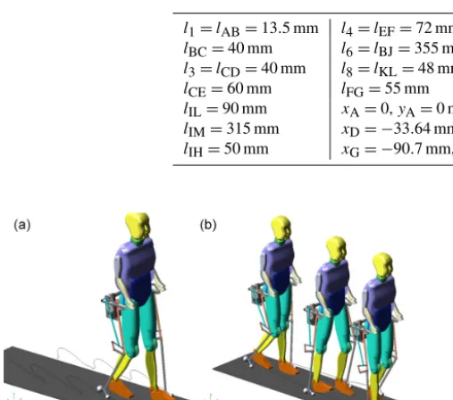
A virtual model of the exoskeleton, consisting of two legs attached to an upper frame, and a chain transmission for ac-tuation of the legs is designed in SolidWorks for dynamic simulation. The links 1 of left and right legs are opposite positioned to 180◦. According to the kinematic scheme pre-sented in Fig. 7, the exoskeleton design, comprising all of its components, is performed and presented in Fig. 14. The mannequin is modeled with all anatomical parts (trunk, arm and legs), and movable leg links (femur, tibia and foot) based on anthropomorphic data of the patient. The anatomical parts of mannequin are defined as geometry and inertial properties (by adding material density). The simulation system is de-fined by 25 revolute joints for the exoskeleton system, 6 revo-lute joints for the mannequin, and suitable fixed joints used in order to attach the exoskeleton to the mannequin. The chain transmission which has the role of rotating the shaft and the legs motor links 1, is also designed. All the revolute joints of the system have been defined considering the Coulomb friction model, respectively: the static friction coefficient is considered equal to 0.1 and the dynamic coefficient is equal to 0.05. In our design, in order to model a proper contact, the foot contact models were defined using two spheres: one for heel and one for plantar area, as we can see in Fig. 15b).
Figure 15.Dynamic model of leg exoskeleton for simulation:(a)ADAMS model;(b)foot ground contact in ADAMS.
Table 1.Design parameters of leg mechanism.
l1=lAB=13.5 mm l4=lEF=72 mm lGH=300 mm lBC=40 mm l6=lBJ=355 mm lGI=350 mm l3=lCD=40 mm l8=lKL=48 mm lHJ=40 mm
lCE=60 mm lFG=55 mm lJK=60 mm
lIL=90 mm xA=0,yA=0 mm Step length=220 mm lIM=315 mm xD= −33.64 mm,yD=45.5 mm Step height=110 mm lIH=50 mm xG= −90.7 mm,yG= −32 mm β=65◦
Figure 16.Snapshots of simulation outputs of the exoskeleton and mannequin walking.
was (Patton et al., 1993):
F(x, v)=4.658×1010x4+9.719×1010x4·v (2)
where:F is the resulting contact force,x is the penetration depth andvis the velocity of penetration. The ADAMS con-tact modeling tools do not allow for such a polynomial func-tion to be introduced in the model, but offer instead the fol-lowing cubic function (with IMPACT method used to define the contact), (Patton et al., 1993):
F(x, v)=kx+nc(x/d)2×
3−2x/do
v (3)
where:kis a linear spring constant,cis the damping coef-ficient and d is the depth of penetration. The estimates of
the ADAMS impact coefficients, upon Meglan relations are:
k=250 N mm−2; c=15 N mm−1s−1 and d=5 mm. The exoskeleton contact parameters and also designed foot model are shown in Fig. 15.
The torsion spring damper, placed at ankle joint uses the coefficients: (Krot)=1 N rad−1 – representing the stiffness coefficient and (Crot)=1N mm rad−1– the damping coeffi-cient (Kesckemethy et al., 2011).
The simulation settings for the mannequin – exoskeleton assembly were considered as real. The model of the man-nequin was positioned in the bipedal position when the left foot touches the ground and the right leg is in the balanc-ing phase. This is the same startbalanc-ing position of the man sub-jected to experimental walking analysis. Simulation of the exoskeleton in MSC.ADAMS is proposed for the case of assistance to a patient with a leg disability. A sequence of exoskeleton with mannequin walking positions is shown in Fig. 16.
For the simulation, input angular velocity is set up to 4 rad s−1. When the motor rotates 180◦, the bipedal mech-anism moves one step forward.
Figure 18.Computed displacement of the left leg exoskeleton ankle joint:(a)onxaxis;(b)onyaxis.
Figure 19.Computed vertical reaction force on the exoskeleton hip joint:(a)left joint;(b)right joint.
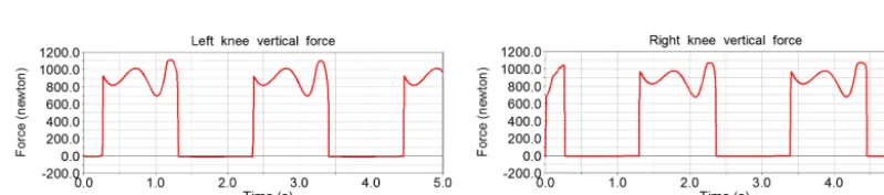
Figure 20.Computed vertical reaction force on the exoskeleton knee joint:(a)left knee;(b)right knee.
the right hip joint vary in the range [−25; 16◦], with a max-imum amplitude equal to 41◦, while for the right knee joint the computed angular amplitude vary in the range [0; 65◦] and the maximum amplitude is 65◦. The values of computed amplitudes are similar with the ones obtained by experimen-tal analysis, presented in Figs. 3 and 4.
Figure 18 shows computed displacements of the left leg exoskeleton ankle joint, upon horizontal axis Fig. 18a and vertical axis Fig. 18b. In the first phase the leg is on the ground during 1.5 s, and then the leg is performing the swing phase, with a step length by 440 mm. The step length per-formed when the exoskeleton is performing gait is bigger
than in situation when the mechanism operates at stationary with 220 mm (is double). This fact is confirmed also by the experimental analysis of the exoskeleton gait.
Figure 21.Computed exoskeleton ground reaction forces (GRF):(a)for left leg;(b)for right leg.
Figure 22.Computed actuator parameters:(a)zaxis motor torque;(b)motor power magnitude.
Figure 23.A view of exoskeleton manufactured prototype:(a) iso-metric view;(b)lateral view.
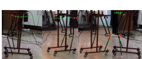
Figure 24.Marker tracking for exoskeleton kinematics:(a, b) com-putation of trajectories; (c, d)computation of knee joints angular variation.
the exoskeleton ground reaction forces for both legs. The maximum value is 1130 N, also a value correlated with the weight of the assisted virtual mannequin (patient). Figure 22 shows computed torque of driving motor on rotation axis and computed power of the actuator. As is observed the time for a step is about 1.5 s, and the time period of one walking
op-eration cycle (two steps) is 3 s. The peaks values are 14 Nm, corresponding to the ground contact phase of the legs. For the swing phase of the exoskeleton the values for the forces and computed torque are smaller. Computed diagrams for the legs show repetitive variations. Simulation results allow con-cluding that the leg exoskeleton design is suitable for human gait rehabilitation.
6 Experimental characterization of the exoskeleton
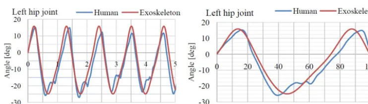
inter-Figure 26.Compared variation of hip joint angle for human subject and for exoskeleton model.
est points, like hip, knee and ankle joint are attached and their captured motion trajectories are shown in Fig. 24a and b.
Joints angle variation is computed based on marker track-ing (Fig. 24c, d). Numerical results, obtained for the ex-oskeleton joint variations are compared with those achieved by the human subject. For the human subject hip and knee joint angular variation a medium cycle is calculated.
A comparison of the achieved left knee joint angular vari-ation for the exoskeleton and human healthy subject is pre-sented in Fig. 25. Also because of the human gait variabil-ity for a relevant comparison are presented on the same di-agram the variations for the exoskeleton knee joint and the human subject medium cycle, for a gait cycle. It can be ob-served that the maximum angular amplitude for the human and exoskeleton knee joint is 65◦. Because the human gait presents variability from one step to another and from one subject to another, one can observe in Fig. 25 that the pe-riod corresponding to each step made by the human subject differs from one to other. The steps performed by the ex-oskeleton do not present variability. For the comparison the medium cycle of the human subject is used. For more ac-curate results, considering the natural biological variability from one’s individual step to another, 19 consecutive cycles of flexion-extension angle were selected (after removing the first three cycles and the last three cycles), and, then, were normalized by interpolation in SimiMotion software and re-ported on the abscissa at a scaled interval from 0 to 100 %. For each trial the mean cycle was obtained, and, finally, the
mean cycle of the experimental test was obtained based on the five mean cycles corresponding to the five trials.
By comparing the five maximum values of the mean cycles of knee flexion-extension with the maximum value of the fi-nal mean cycle corresponding to the test, we can conclude that, these are very close with non-significant differences. There were not big differences in the shape of the flexion an-gle. The minor differences obtained by this comparison show a good repeatability of the imposed test for all the five trials. The maximum values of the knee angle determined during the performed trials were compared and tested with a Student
t-test, consideringα=0.05. The P-values corresponding to these tests are calculated using ANOVA. The conclusion is that the maximum flexion angles were not significantly dif-ferent (tcalc=2.09< tcr=2.31 andp=0.0785>0.05).
human mannequin. For that purpose a dynamic simulation model in ADAMS is developed. The results obtained by nu-merical simulation are discussed and compared with exper-imental results obtained on healthy human subjects. Based on the CAD design an experimental prototype of the ex-oskeleton is manufactured in order to perform experimen-tal studies and to validate the results obtained by numeri-cal simulation. The exoskeleton real model motion analysis is performed using Contemplas ultra speed video cameras equipment and analysis software. The motion of the exper-imental prototype is compared with results of virtual simula-tion mosimula-tion and with results of the human gait experimental analysis. Obtained results are used to characterize the oper-ation of the leg proposed exoskeleton. Finally is presented a comparison of exoskeleton motion compared results. The exoskeleton hip and knee joints angular motion it is com-pared with human healthy subject motion and the obtained variation graphics are similar. In conclusion, the mechanism operation is suitable for human motion assistance and reha-bilitation purposes.
xK+l8·cosϕ8=xI+lIL·cosϕ9
yK+l8·sinϕ8=yI+lIL·sinϕ9
(A4)
Solutions of Eqs. (A1)–(A4) are found by solving nonlin-ear Eq. (A5), with variable coefficients. These loop closure equations are solved using a package program developed on Maple environment.
Aisinϕi+Bicosϕi+Ci=0;i=2,9.
ϕi =2 arctg
Ai± q
A2i +Bi2−Ci2 Bi−Ci
(A5)
where the variable coefficients Ai, i=2,9, are computed with Eq. (A6):
A2=2b1lBC;B2=2a1lBC;C2=l32−a12−b21−l2BC; A3= −2b1l3;B3= −2a1l3;C3=lBC2 −a12−b21−l32 A4=2b2l4;B4=2a2l4;C4=lGF2 −l24−a22−b22; A5= −2b2lGF;B5= −2a2lGF;C5=l42−lGF2 −a22−b22 A6=2c2lBJ;B6=2c1lBJ;C6=lJH2 −c21−c22−lBJ2 ; A7= −2c2lJH;B7= −2c1lJH;C7=lBJ2 −c12−c
2 2−l
2 JH A8=2d2l8;B8=2d1l8;C8=lIL2 −d12−d
2 2−l
2 8; A9= −2d2lIL;B9= −2d1lIL;C9=lIL2 −d12−d22−l28 where
a1=xD−xB, b1=yD−yB;a2=xG−xE, b2=yG−yE c1=xH−xB, c2=yH−yB;d1=xI−xK, d2=yI−yK
(A6)
+lFG·cosϕ5·ω5+lGI·cos (ϕ5+π/2)·ω5 +lIM·cos (2π−β+ϕ9)·ω9
The components of the point M acceleration on both axes are given by the Eq. (3):
axM= −l1·cosϕ1·ω21−l1·sinϕ1·ε1−lBE·cosϕ2·ω22 −lBE·sinϕ2·ε2−l4·cosϕ4·ω24−l4·sinϕ4·ε4 −lFG·cosϕ5·ω52−lFG·sinϕ5·ω5
−lGI·cos (ϕ5+π/2)·ω52−lGI·sin (ϕ5+π/2)·ε5 −lIM·cos (2π−β+ϕ9)·ω29
−lIM·sin (2π−β+ϕ9)·ε9
ayM= −l1·sinϕ1·ω21+l1·cosϕ1·ε1−lBE·sinϕ2·ω22 +lBE·cosϕ2·ε2−l4·sinϕ4·ω24+l4·cosϕ4·ε4 −lFG·sinϕ5·ω52+lFG·cosϕ5·ε5
−lGI·sin (ϕ5+π/2)·ω52+lGI·cos (ϕ5+π/2)·ε5 −lIM·sin (2π−β+ϕ9)·ω92
+lIM·cos (2π−β+ϕ9)·ε9
(A9)
where:ϕideg, i=2,9−angular variations;
ωi
degs, i=2,9−angular velocity;
References
Anama, K. and Al-Jumaily, A. A.: Active Exoskeleton Control Sys-tems: State of the Art, Procedia Engineer. 41, 988–994, 2012. Ashkani, O., Maleki, A., and Jamshidi, N.: Design,
simula-tion and modelling of auxiliary exoskeleton to improve hu-man gait cycle, Australas. Phys. Eng. S., 40, 137–144, https://doi.org/10.1007/s13246-016-0502-6, 2016.
Banala, S. K., Agrawal, S. K., and Scholz, J. P.: Active Leg Ex-oskeleton (ALEX) for Gait Rehabilitation of Motor-Impaired Pa-tients, Proceedings of the 2007 IEEE 10th International Confer-ence on Rehabilitation Robotics, 12–15 June, Noordwijk, The Netherlands, 401–407, 2007.
Barbareschi, G., Richards, R., Thornton, M., Carlson, T., and Holloway, C.: Statically vs dynamically balanced gait: Anal-ysis of a robotic exoskeleton compared with a human, Conf. Proc. IEEE Eng. Med. Biol. Soc., 2015, 6728–6731, https://doi.org/10.1109/EMBC.2015.7319937, 2015.
Begg, R. K., Wytch, R., and Major, R. E.: Instrumentation used in clinical gait studies: a review, J. Med. Eng. Technol., 13, 290– 295, 1989.
Bortole, M., Venkatakrishnan, A., Zhu, F., Moreno J. C., Francisco, G. E., Pons J. L., and Contreras-Vidal, J. L.: The H2 robotic exoskeleton for gait rehabilitation after stroke: early findings from a clinical study, J. Neuroeng. Rehabil., 12, PMC4469252, https://doi.org/10.1186/s12984-015-0048, 2015.
Bruzzone, L. and Quaglia, G.: Review article: locomotion systems for ground mobile robots in unstructured environments, Mech. Sci., 3, 49–62, https://doi.org/10.5194/ms-3-49-2012, 2012. Carbone, G., Ottaviano, E., and Ceccarelli, M.: An optimum design
procedure for both serial and parallel manipulators, J. Mech. Eng. Sci., 221, 829–843, 2007.
Carbone, G. and Ceccarelli, M.: A mechanical design of a low-cost easy-operation anthropomorphic wheeled leg for walking ma-chines, Int. J. Robot. Manage., 9, 3–8, 2008.
Ceccarelli, M. and Romdhane, L.: Design issues for human-machine platform interface in cable-based parallel manipulators for physiotherapy applications, J. Zhejiang Univ. Sci., 11, 231– 239, https://doi.org/10.1631/jzus.A1000027, 2009.
Ceccarelli, M., Cafolla, D., Wang, M., and Carbone, G.: An Overview of the Ongoing Humanoid Robot Project LARMbot, in: Towards Autonomous Robotic Systems, edited by: Alboul, L., Damian, D., and Aitken, J., TAROS 2016, Lecture Notes in Computer Science, Vol. 9716, Springer, 2016.
Chen, G., Chan, C. K., Guo, Z., and Yu, H.: A review of lower extremity assistive robotic exoskeletons in rehabilitation therapy, Crit. Rev. Biomed. Eng., 41, 343–363, 2013.
Copilusi, C., Ceccarelli, M., and Carbone, G.: Design and numerical characterization of a new leg exoskeleton for motion assistance, Robotica, 33, 1147–1162, 2015.
de Looze, M. P., Bosch, T., Krause, F., Stadler, K. S., O’Sullivan, L. W.: Exoskeletons for industrial application and their
poten-Dumitru, N., Copilusi, C., Geonea, I., Tarnita, D., and Dumitrache, I.: Dynamic Analysis of an Exoskeleton New Ankle Joint Mech-anism, New Trends in Mechanism and Machine Science Mecha-nisms and Machine Science, Vol. 24, Springer International Pub-lishing, 709–717, 2015.
Geonea, I. D., Alexandru, C., Margine, A., and Ungure-anu, A.: Design and simulation of a single DOF human-like leg mechanism, Appl. Mech. Mat., 332, 491–496, https://doi.org/10.4028/www.scientific.net/AMM.332.491, 2013.
Geonea, I., Ceccarelli, M., and Carbone, G.: Design and analysis of an exoskeleton for people with motor disabilities, in: The 14th IFToMM World Congress, Taipei, Taiwan, 2015.
Hesse, S., Schmidt, H., Werner, C., and Bardeleben, A.: Upper and lower extremity robotic devices for rehabilitation and for study-ing motor control, Curr. Opin. Neurol., 16, 705–710, 2003. Ilhem, B., Lepagnot, J., and Siarry, P.: A survey on
opti-mization metaheuristics, Information Sciences, 237, 82–117, https://doi.org/10.1016/j.ins.2013.02.041, 2013.
Jarrassé, N., Proietti, T., Crocher, V., Robertson, J., Sahbani, A., Morel, G., and Roby-Brami, A.: Robotic exoskeletons: a perspective for the rehabilitation of arm coordination in stroke patients, Front. Hum. Neurosci., 1, 8:947, PMC4249450, https://doi.org/10.3389/fnhum.2014.00947, 2014.
Kao, P. C., Lewis, C. L., and Ferris, D. P.: Invariant ankle mo-ment patterns when walking with and without a robotic ankle exoskeleton, J. Biomech., 43, 203–209, 2010.
Kecskemethy, A.: Integrating efficient kinematics in biome-chanics of human motions, Procedia IUTAM, 2, 86–92, https://doi.org/10.1016/j.piutam.2011.04.009, 2011.
Lajeunesse, V., Vincent, C., Routhier, F., Careau, E., and Michaud F.: Exoskeletons’ design and usefulness evidence according to a systematic review of lower limb exoskele-tons used for functional mobility by people with spinal cord injury, Disabil. Rehabil. Assist. Technol., 11, 535–547, https://doi.org/10.3109/17483107.2015, 2016.
Li, T., and Ceccarelli, M.: Design and simulated characteristics of a new biped mechanism, Robotica, 33, 1568–1588, 2015. Louie, D. R. and Eng, J. J.: Powered robotic exoskeletons in
post-stroke rehabilitation of gait: a scoping review, J. Neuroeng. Re-habil., 13, 53, https://doi.org/10.1186/s12984-016-0162-5, 2016. Lu, T. W. and Chang, C. F.: Biomechanics of human movement and its clinical applications, Kaohsiung J. Med. Sci., 28, S13– 25, 2012.
Meglan, D. A. and Berme, N.: A 3D Passive Mechanical Model of the Human Foot for Use in Locomotion Synthesis, Second North American Congress of Biomechanics, Chicago, 351–352, 1992. Meng, L., Ceccarelli, M., Yu, Z., Chen, X., and Huang, Q.: An
Rahman, T., Sample, W., Jayakumar, S., King, M. M., Wee, J. Y., Seliktar, R., Alexander, M., Scavina, M., and Clark, A.: Passive exoskeletons for assisting limb movement, J. Rehabil. Res. Dev., 43, 583–590, 2006.
Rajesh Shah, M.: Design of Human Exo-Skeleton Suit for Rehabil-itation of Hemiplegic People, Proc. Eng., 51, 544–553, 2013. Schorsch, J. F., Keemink, A. Q. L., Stienen, A. H. A., van der Helm,
F. C. T., and Abbink, D. A.: A novel self-aligning mechanism to decouple force and torques for a planar exoskeleton joint, Mech. Sci., 5, 29–35, https://doi.org/10.5194/ms-5-29-2014, 2014. Sutherland, D. H.: The evolution of clinical gait analysis, Part II
kinematics, Gait Posture, 16, 159–179, 2002.
Tao, W., Liu, T., Zheng, R., and Feng, H.: Gait analysis using wear-able sensors, Sensors, 12, 2255–2283, 2012.
Tarnita, D., Catana, M., and Tarnita, D. N.: Experimental measure-ment of flexion-extension movemeasure-ment in normal and osteoarthritic human knee, Romanian J. Morphol. Embryol., 54, 309–313, 2013.
Tarnita, D.: Wearable sensors used for human gait analysis, Rom. J. Morphol. Embryol., 57, 373–382, 2016.
Tarnita, D., Geonea, I., Petcu, A., and Tarnita, D. N.: Experimental Characterization of Human Walking on Stairs Applied to Hu-manoid Dynamics, Advances in Robot Design and Intelligent Control, Springer, 293–301, 2017.
Tedeschi, F. and Carbone, G.: Hexapod Walking Robot Locomo-tion, In Motion and Operation Planning of Robotic Systems; Springer International Publishing, New York, NY, USA, 439– 468, 2015.
Viteckova, S., Kutilek, P., and Jirina, M.: Wearable lower limb robotics: A review, Journal Biocybern. Biomed. Eng., 33, 96– 105, https://doi.org/10.1016/j.bbe.2013.03.005, 2013.
Wang, S. and Wang, L.: Design and control of the MINDWALKER exoskeleton, IEEE Trans. Neural. Syst. Reh., 23, 277–286, https://doi.org/10.1109/TNSRE.2014.2365697, 2015a.
Wang, M. F., Ceccarelli, M., and Carbone G.: Experimen-tal tests on operation performance of a LARM leg mecha-nism with 3-DOF parallel architecture, Mech. Sci., 6, 1–8, https://doi.org/10.5194/ms-6-1-2015, 2015b.
Winter, D. A.: Biomechanics of Human Movement, John Wiley & Sons Inc., 1979.
Wojtyra, M.: Multibody Simulation Model of Human Walking, Me-chanics Based Design of Structures and Machines, 31, 357–379, 2003.
Young Aaron, J. and Ferris, D. P.: State-of-the-art and Future Directions for Lower Limb Robotic Exoskele-tons, IEEE Trans. Neural. Syst. Rehabil. Eng., 171–182, https://doi.org/10.1109/TNSRE.2016.2521160, 2017.