http://www.sciencepublishinggroup.com/j/ijmea doi: 10.11648/j.ijmea.20190703.11
ISSN: 2330-023X (Print); ISSN: 2330-0248 (Online)
Parametric Study of Drivetrain Dynamics of a Wind Turbine
Using the Multibody Dynamics
Wei Shi
1, 2, 3, 4, Dezhi Ning
1, 3, Zhe Ma
2, Nianxin Ren
2, 3, Hyunchul Park
51State Key Laboratory of Coast and Offshore Engineering, Dalian University of Technology, Dalian, China 2Deepwater Engineering Research Center, Dalian University of Technology, Dalian, China
3
Offshore Renewable Energy Research Center, Dalian University of Technology, Dalian, China
4State Key Laboratory of Hydraulic Engineering Simulation and Safety, Tianjin University, Tianjin, China 5Department of Mechanical Engineering, Pohang University of Science and Technology, Pohang, Korea
Email address:
To cite this article:
Wei Shi, Dezhi Ning, Zhe Ma, Nianxin Ren, Hyunchul Park. Parametric Study of Drivetrain Dynamics of a Wind Turbine Using the Multibody Dynamics. International Journal of Mechanical Engineering and Applications. Vol. 7, No. 2, 2019, pp. 66-77.
doi: 10.11648/j.ijmea.20190703.11
Received: June 20, 2019; Accepted: July 22, 2019; Published: August 5, 2019
Abstract:
Wind energy has become one of the most cost-effective and environmental friendly renewable energy resources among all exploited renewable energy. However, the failure of gearbox contributes most of the downtime for wind turbine system. Dynamic properties of drivetrain, including gearbox should be investigated in detail further. In present paper, a mathematical model for a horizontal axis wind turbine drivetrain was developed using the torsional multibody dynamic model. The drivetrain in this study consisted of a low-speed planetary gear stage (three identical planets with spur teeth, sun and fixed ring gears) and two high-speed spur gear stages. This typical arrangement has been commonly used in the wind turbine industry. Based on this model, this paper aims to investigate the influence of drivetrain parameters on the dynamic response of the wind turbine. The dynamic responses of the turbine with different rotor inertia and generator inertia are compared. Then the difference due to changing of the shaft stiffness is also investigated during and after the transient condition. This parametric study shows that lower rotor inertia and generator inertia could lead to more oscillations.Keywords:
Wind Turbine, Drivetrain, Multibody Dynamics, Transient Condition1. Introduction
The growing awareness of the threat of climate change caused by greenhouse gas has brought wind energy to the top of the global consensus, and wind energy has become the most cost-effective of all currently exploited renewable energy resources and has attracted extensive research and business interest [1-2]. Besides the industrial application success, extensive research is also carried out outside of the commercial companies [3-6].
The increased sizes of rotor and turbine have led to a complex design of the drivetrain mechanism. As one of the most critical components on the operation of wind turbines, the drivetrain is responsible for most of the downtime and results in the increment in operational costs [7]. Various studies have addressed the dynamic
modeling of wind turbines [8]. However, few studies have focused on the advanced dynamic modeling of drivetrain [9-13].
2. Mathematical Model of the Wind
Turbine Drivetrain
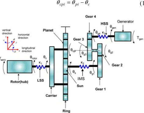
The lumped parameter dynamic model of the drivetrain investigated in this study is shown in Figure 1. With one DOF for each component, the dynamic model has ten DOFs. Each gear, i, has a polar moment of inertia of Ji, i = rotor, c, p1, p2, p3, s, g1, g2g3, g4, gen, for the rotor, the carrier, the planets 1, 2, 3, the sun, the gears 1, 2 and 3, 4 and the generator, respectively; kj, j = 1, 2, 3, is the torsional stiffness for the Low Speed Shaft (LSS), Intermediate Shaft (IMS) and High Speed Shaft (HSS), respectively. The shaft connecting gears 2 and 3 (Figure 1) was assumed to be rigid due to immediately adjacent gears. The parameter ri is the base circle radius for each gear component and rc is the radius of the circle passing through the planet centers for the carrier. The angular displacements of the central members, θrotor, θc, θs, θg1, θg2g3, θg4, θgen,were defined as absolute displacements about a fixed coordinate frame, whereas the angular displacements of planets, θcp1, θcp2, θcp3, were defined relative to the carrier c as:
cpi pi c
θ =θ −θ (1)
Figure 1. Dynamic modeling of wind turbine drivetrain.
Figure 2. (a) Planet gear stage model, (b) parallel gear stage model.
The linear springs with time-varying stiffness krp(t), ksp(t), kg12(t) and kg34(t) were used to model the gear mesh [14] (Figure 2). Each mesh stiffness is expressed in the Fourier series as:
( )
(
( ) ( ) ( ) ( ))
=0
= + rp l sin p + l cos p
rp rp rp M rp M
rp l
k
k t k a t b t
C
ω
ω
∞
∑
(2)( )
(
( ) ( ) ( ) ( ))
=0
= + sp l sin p + l cos p
sp sp sp M sp M
sp l
k
k t k a t b t
C
ω
ω
∞
∑
(3)where krp and ksp are mean values. The Fourier coefficients are given as:
( ) 2
(
) (
)
= sin 2 sin
l
rp rp rp rp
a l C l C
lπ π γ π
− − (4)
( ) 2
(
) (
)
= cos 2 sin
l
rp rp rp rp
b l C l C
lπ π γ π
− − (5)
( ) 2
(
) (
)
= sin 2 sin
l
sp sp sp sp
a l C l C
lπ π γ π
− − (6)
( ) 2
(
) (
)
= cos 2 sin
l
sp sp sp sp
b l C l C
lπ π γ π
− − (7)
where Csp, Crp are sun-planet contact ratio and ring-planet contact ratio; γsp, γrp are phase angle of sun-planet gear pair and ring-planet gear pair.
Similar mesh stiffness is defined for the parallel gear stage, except that there are different gear mesh frequencies (GMFs) and contact ratios. The mesh stiffness for the ring–planet, the sun–planet and the gears 1–2 and 3–4 are presented in Figure 3.
The GMF for each gear mesh pair can be determined from kinematic relationships as:
( )p = c r
M N
ω ω (8)
( )12
1 1 =
g
g g
M N
( 34) 3 3 = g g g M N
ω ω (10) The relative gear mesh displacements of the sun–planet and the ring–planet gear mesh are defined as:
spi rs s rc c rpi pi
δ = θ − θ + θ (11)
rpi rr r rc c rp pi
δ = θ − θ − θ (12)
where rr is the radius of the ring gear. A fixed ring gear is assumed in this study, which results in θr = 0.
Figure 3. Time-varying gear mesh stiffness.
Lagrange’s equation was used to derive the EOM [15]. The Lagrangian of the undamped dynamic models shown in Figure 2 with three planets is given as (Kahraman 2001):
( )
( )
(
)
( )
( )
(
)
( )
( )
(
)
(
)
(
)
3 3
2 2 2 2
1 1
2 2 2 2 2
1 1 2 3 2 3 4 4
2 2 2
1 2 1 3 4
1 2
+ + + +
1 1 1
2 2 2
1
2
rotor rotor c p c c p cpi c
i i
s s g g g g g g g g gen gen
rotor c s g g gen
rp r r c
L J J m r J
J J J J J
k k k
k r r
θ θ θ θ θ θ θ θ θ θ θ θ θ θ θ θ θ = = = + + + + + − − − − − − − −
∑
∑
ɺ ɺ ɺ ɺ ɺ ɺ ɺ ɺ ɺ ɺ ɺ(
)
(
)
(
)
(
)
3 2 1 3 2 1 2 212 1 1 2 2 3 34 3 2 3 4 4
2 2 2
1 2 1 1 2 2
1 1 1
2 2 2
c p cpi c i
sp s s c c p cpi c i
g g g g g g g g g g g g
tc c ts s tr r
r
k r r r
k r r k r r
k k k
θ θ θ θ θ θ θ θ θ θ θ θ θ = = − + − − + + − + − + − − −
∑
∑
(13)The Lagrange EOMs of the ten-DOF dynamic model are given as:
i
i i
d L L
Q
dt q q
∂ ∂
− =
∂ ∂
ɺ i= rotor, c, cp1, cp2, cp3, s, g1, g2g3, g4, gen (14)
where a dot over the parameter denotes differentiation with respect to time and ∂ denotes a partial derivative. Eq. (14) together with Eq. (13) leads to eight coupled ordinary differential equations, which can be written in the matrix form as:
Mu+Ku=Q
ɺɺ
(15) where u, M, K, and Q are the displacement vector, the mass matrix the stiffness matrix, and the external force.The aerodynamic torque and electromagnetic torque are considered as external forces.
3. Results and Discussion
3.1. Numerical Analysis Method
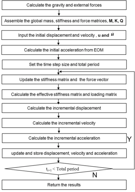
calculated from the solutions at the previous time steps. The unconditional stable Newmark-β method (Figure 4) was used for the numerical analysis by implementing it into the Matlab based on the Eqs. 13~15. The basic integration equations that relate the positions, the velocities and the accelerations from
the time step t to t+∆t are given as follows:
(
1)
t t t t t t
uɺ+∆ = +uɺ −γ uɺɺ +γɺɺu+∆ ∆t (16)
(
)
( )
20.5
t t t t t t t
u+∆ = + ∆u tuɺ + −β uɺɺ +βuɺɺ+∆ ∆t (17)
Figure 4. Flowchart of the numerical method of direct integration method.
Typical parameters of a wind turbine drivetrain from Todorov (2009) are used in this study (Table 1). The rotor is exited with the angular velocity of 18 rpm.
Table 1. System parameters for the drivetrain configurations.
rc- carrier radius (mm) 270
rp- planet radius (mm) 160
rs- sun radius (mm) 110
rg1- radius of gear1 (mm) 290
rg2- radius of gear 2 from the 2nd stage (mm) 95 rg3- radius of gear 3 from the 3rd stage (mm) 185
rg4- radius of gear 4 (mm) 80
Jrotor- inertia of the rotor (kg·m2) 4.18×10⁶
Jc- inertia of the carrier (kg·m2) 57.72
mp- mass of the planet (kg) 57.79
Jp- inertia of the planet (kg·m2) 1.12
Js- inertia of the sun (kg·m2) 0.86
Jg1- inertia of the gear 1 (kg·m2) 14.32
Jg2g3- inertia of the gear 2 and gear 3 (kg·m2) 1.62
Jg4- inertia of the gear 4 (kg·m2) 0.2
Jgen- inertia of the generator (kg•m2) 93.22
k1- stiffness of the LSS (Nm/rad) 7.19×10⁷
k2- stiffness of the internal shaft (Nm/rad) 1.4×10⁷
k3- stiffness of the HSS shaft (Nm/rad) 0.15×10⁷
krp- stiffness of the ring-planet gear mesh in the planetary
gear stage (N/m) 0.73×10
8
ksp- stiffness of the sun-planet gear mesh in the planetary
gear stage (N/m) 0.73×10
8
kg12- stiffness of the gear mesh between gear 1-2 (N/m) 2.02×10⁹ kg34- stiffness of the gear mesh between gear 3-4 (N/m) 0.11×10⁸
Crp-ring-planet contact ratio 1.9342
Csp-sun-planet contact ratio 1.6242
Cg12- contact ratio of gears 1 and 2 1.6616
Cg34- contact ratio of gears 3 and 4 1.5984
α- pressure angle (°) 20
gear ratio 34.654
3.2. Numerical Analysis Results
stiffness are kept as constant.
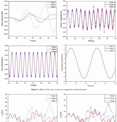
Table 2. Simulation cases for the rotor inertia parameters.
Case 1 Case 2 Case 3
Inertia of the rotor 0.5Jrotor Jrotor 1.5Jrotor
Inertia of the generator Jgen Jgen Jgen
Figure 5 shows the rotational speed of the rotor, planet 1, sun gear and generator, respectively. It is observed that the
rotor inertia has great influence on the rotor and planet 1 and negligible influence on sun gear and generator. Not only the magnitude but also the oscillation period of rotor speed change due to changing of the rotor inertia. The effect of the rotor inertia on the gear contact forces are investigated (Figure 6) and the results show that there is a large increase of the contact force of the ring-planet and sun-planet gear pair but no effect on the parallel gear contact force.
Figure 6. Effect of the rotor inertia on gear contact force.
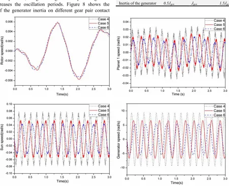
Table 3 summarizes the simulation cases for the generator inertia parameters in which the rotor inertia and shaft stiffness remain constant. Figure 7 shows the response of three cases using different generator inertias. No effect is found on the rotor speed. But the higher generator inertia reduces the planet 1, sun gear and generator speed magnitude but increases the oscillation periods. Figure 8 shows the effect of the generator inertia on different gear pair contact
force. Oscillation periods of all the contact forces are affected by generator inertia but the magnitude remain unchanged.
Table 3. Simulation cases for the generator inertia parameters.
Case 4 Case 5 Case 6
Inertia of the rotor Jrotor Jrotor Jrotor
Inertia of the generator 0.5Jgen Jgen 1.5Jgen
Figure 8. Effect of the generator inertia on gear contact force.
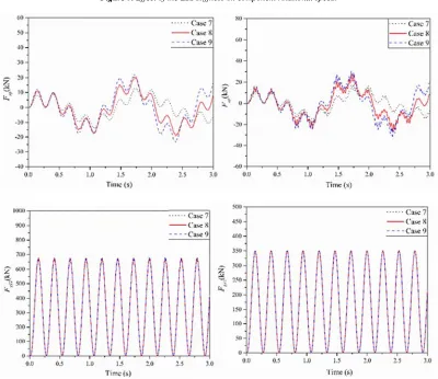
3.2.2. Effects of Shaft Stiffness Parameters
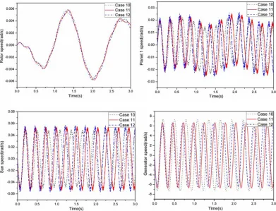
Table 4~6 summarizes considered cases for different LSS, IMS, and HSS stiffness parameters, respectively. LSS stiffness only has a small influence on the rotor speed while negligible effects can be found for other components (Figure 9). With increasing of the LSS stiffness, the contact force between ring gear and planet gear and the contact force between sun gear and planet gear increase but no effect on the parallel gear stage (Figure 10). Due to the different IMS
stiffness, the oscillation period of the planet 1, sun gear and generator speed change significantly (Figure 11). Similar effect on the oscillation period can be identified for all the gear contact forces (Figure 12). The oscillation period of the planet 1, sun gear and generator change a little because of the increasing of the HSS stiffness (Figure 13). The reduction of the oscillation period for all the gear stages can be found with increasing of HSS stiffness (Figure 14).
Table 4. Simulation cases for the LSS stiffness parameters.
Case 7 Case 8 Case 9
LSS stiffness 0.5K1 K1 1.5K1
IMS stiffness K2 K2 K2
HSS stiffness K3 K3 K3
Table 5. Simulation cases for the IMS stiffness.
Case 10 Case 11 Case 12
LSS stiffness K1 K1 K1
IMS stiffness 0.5K2 K2 1.5K2
Figure 9. Effect of the LSS stiffness on component rotational speed.
Figure 11. Effect of the IMS stiffness on component rotational speed.
Table 6. Simulation cases for the HSS parameters.
Case 13 Case 14 Case 15
LSS stiffness K1 K1 K1
IMS stiffness K2 K2 K2
HSS stiffness 0.5K3 K3 1.5K3
Figure 14. Effect of the HSS stiffness on gear contact force.
4. Conclusions
A mathematical model of the drivetrain in a horizontal wind turbine was proposed. The model used multibody dynamics to investigate the torsional vibration in the drivetrain. The governing equation was derived using Lagrange’s equation. The model took into account the flexibility of the gear mesh by using linear springs with time-varying stiffness and shaft torsion.
The equations of motion of the drivetrain were solved numerically by the direct integration method to obtain the transient response of the system. The parameter studies were carried out based on the proposed model. The following conclusions can be drawn from this study:
1) The generator inertia has most significant effect on the response of the components.
2) Higher generator inertia can reduce the oscillation range and delay the oscillation period.
3) LSS stiffness has negligible effects while IMS and HSS stiffness can reduce the period of the component speed response.
4) Rotor inertia and LSS stiffness have a large effect on the contact force magnitude of the ring-planet and sun-planet gear pair but limited effect on the parallel gear stage contact force.
Acknowledgements
The authors would like to gratefully acknowledge financial support from the National Science Foundation of China (Grant No. 51709039, 51761135011). This work is also partially supported by the Fundamental Research Funds for the Central Universities (DUT19GJ209) and State Key Laboratory of Hydraulic Engineering Simulation and Safety.
References
[1] Dincer F (2011) The analysis on wind energy electricity generation status, potential and policies in the world. Renew Sust Energ Rev 15 (9): 5135-5142.
[2] Luhur MR, Manganhar AL, Solangi KH, Jakhrani AQ, Mukwana K C, Samo S R (2016) A review of the state-of-the-art in aerodynamic performance of horizontal axis wind turbine. Wind Struct 22 (1): 1-16.
[3] Jonkman JM (2009) Dynamics of offshore floating wind turbines - model development and verification. Wind Energy, 12 (5): 459-492.
[4] Kim CH, Kim KS, Kim HY, Paek IS, Yoo NS, Nam YS, Campagnolo F, Bottasso C (2012) A method to estimate bending moments acting on a wind turbine blade specimen using FBG sensors. Int. J. Precis. Eng. Manuf 13 (7): 1247-1250.
[5] Shi W, Park HC, Na S, Song J, Ma S, Kim CW (2014) Dynamic analysis of three-dimensional drivetrain system of wind turbine. Int J Precis Eng Manuf 15 (7): 1351-1357. [6] Zhang JP, Li DL, Han Y, Hu DM, Ren JX (2013) Dynamic
stability analysis on large wind turbine blade under complicated offshore wind conditions. J Vibroeng 15 (3): 1597-1605.
[7] Oyague F (2009) Gearbox Modeling and Load Simulation of a Baseline 750-kW Wind Turbine Using State-of-the-Art Simulation Codes. Technique report NREL/ TP-500-41160. [8] Dresig H, Schreiber U (2005) Vibration Analysis for Planetary
Gears, Modeling and Multibody Simulation. Proceedings of ICMEM2005, Nanjing, China, October.
[9] Shi W, Kim CW, Chung CW, Park HC (2012) Dynamic Modeling and Analysis of a Wind Turbine Drivetrain Using the Torsional Dynamic Model. Int J Precis Eng Manuf 14 (1): 153-159. [10] Shi W, Park YH, Park HC, Ning DZ (2018) Dynamic analysis
[11] Todorov M, Vukov G, Dovbrev I (2009) Analysis of torsional oscillation of the drivetrain in horizontal axis wind turbine. Electromotion-2009-EPE Chapter ‘Electric Drives’ Joint Symposium Lille, France.
[12] Todorov M, Vukov G (2010) Parametric torsional vibrations of a drive train in horizontal axis wind turbine. Proceedings of CFSER-2010, Damas.
[13] Wu X, Ma Z, Rui X, Yin W, Zhang M, Ji K (2016) Speed control for the continuously variable transmission in wind turbines under subsynchronous resonance. IJST-T Mech Eng 40 (2): 151-154.
[14] Lin J, Parker RG (2002) Planetary gear parametric instability caused by mesh stiffness variation. J Sound Vibr 249 (1): 129-145.
[15] Shabana A (2010) Computational Dynamics, John Wiley & Sons, Inc, Ed., New York.