Jun-Jae Lee 9 Gwang-Chul Kim
Study on the estimation of the strength properties of structural glued
laminated timber I: determination of optimum MOE as input variable
Received: December 7, 1998 / Accepted: June 14, 1999
Abslract There have been many attempts to predict the performance of glulam beams. Several approaches have been taken, from early empirical techniques to more sophis- ticated stochastic methods. In recent years, more emphasis has been placed on the modeling of material properties. Generally, the modulus of elasticity (MOE) has been used as a criterion of laminar strength for the prediction of glulam performance in the traditional models. Most of the current models are based on M O E that was measured using the long span test; that is, they account only for variability between pieces of lumber. Therefore, these models do not account for the variation of material properties within a given piece of lumber. Five methods were considered to choose the appropriate one that could effectively predict the performance of glulam in this study. Prediction of glulam performance was done by the transformed section method. MOEs measured with the five methods were ap- plied to a strength prediction program to compare the ac- tual test results and the predicted results. MOEs used as input variables are as follows: long span M O E of the static bending test, localized M O E of the static bending test, long span M O E of the stress wave test, localized M O E of the stress wave test, and M O E of the machine stress rating (MSR) test. Results of the localized test showed excellent signification compared to those of the long span test. The MSR method, when used as input variable, obtained the most approximate result, so it is considered adequate for predicting the strength of glulam.
Key words Long span M O E 9 Localized M O E 9 Machine stress rating test 9 Stress wave test 9 Glulam
J.-J. Lee (2~) . G-C. Kim
College of Agriculture and Life Sciences, Seoul National University, Suwon 441-744, Korea
Tel. +82-331-290-2603; Fax +82-331-293-9376 e-mail: [email protected] or [email protected]
An outline of this paper was presented at the 48th annual meeting of the Japan Wood Research Society, Shizuoka, April 1998
Introduction
There have been many attempts to predict the performance of glulam beams. Several approaches have been taken, from early empirical techniques to more sophisticated stochastic methods. In recent years, more emphasis has been placed on the prediction of material properties. At first, glulam performance was predicted with a regression approach that has been proven by the test results for laminar strength and glulam strength. ~ 6 Efforts to predict glulam beam perfor- mance were also done by empirical methods, referred to as the IK/I o method. This method accounts for the strength- reducing influence of knots as a function of the moment of inertia and is the basis for the current industry standard. However, statistical distributions of glulam beam strength are not predicted with this method, and the influence of end joints cannot be studied. Another approach taken to ana- lyze glulam beams was the transformed section method. 7-9 The input value for this method consisted of beam geom- etry and configuration as well as allowable fiber stresses for each lamination. A model developed by Bender and Taylor was widely used to predict glulam performance, but this method has a weak point in that only long span M O E was used as an input value. 1~
Because of the recent shift to reliability-based design, the major focus of glulam research has been to model statis- tical distributions of beam strength accurately. To meet this objective, numerical methods have been widely used to de- velop more accurate criteria of strength prediction, n-13
All these traditional methods have been used lamina strength as an input value to predict glulam performance. Specifically, for material reuse and economic reasons the modulus of elasticity (MOE) has generally been used instead of the modulus of resistance (MOR) as a criterion of lamina strength for the prediction of glulam performance.
on the way in which the M O E is measured. Correlation coefficients of 0.65-0.70 are typical when the M O E is deter- mined as an apparent modulus during a bending test of the lumber piece over its entire length. It is also known that if the approximate variation of M O E is measured along the span the correlation improves when strengths are compared with the lowest, most localized M O E values. It can then be assumed that the efficiency of M O E as a predictor of strength could be improved if M O E were truly a localized measure, reflecting the point-to-point variation along the piece of lumber. However, most current models are based on MOEs measured in long span tests; that is they account only for the variability among different pieces of lumber. Therefore, these models could not account for the variation of material properties within a given piece of lumber. This information for within-piece variability is critical for the structural analysis techniques that require localized pro- perties of individual elements, such as the finite element method.
The M O E of lumber shows a significant variation from the evaluating methods. Hence, the accuracy of prediction for glulam performance depends on the evaluation methods of M O E of lamina. Therefore, five test methods were con- sidered before choosing the appropriate one that could ef- fectively predict the performance of glulam. MOEs that were used as input variables are as follows: localized M O E for the stress wave method; long span M O E for the stress wave method; localized M O E for the static bending method; long span M O E for the static bending method; and mean M O E for the bending test by machinery (MSR, ma- chine stress rating) method. Thus, five evaluation methods were used to choose the appropriate method for input vari- ables. Glulam performance was predicted using these five results as input variables. It is desirable to obtain M O R by measuring each lamina to predict glulam MOR; however, if the M O R of the lamina were used as an input variable, accurate correlation between laminar strength and glulam strength could not be used to determine the loss of lamina during the test. So, the M O R of glulam was also predicted with the M O E of lamina. In other words, the M O R of lamina was converted by the M O E of lamina, and then the M O R of glulam was predicted with these converted MORs of lamina. The objective of this study was to determine the most effective method for selecting the appropriate input variable for predicting glulam performance.
To manufacture glulam with maximum combination of lamina, the laminae were divided into three groups (60 pieces of lumber per group) according to the M O E deter- mined by the machine stress rating (MSR) test as follows:
Group no. MOE (10Skg/cm 2)
[ >I18
II 10@-118
III <100
Glulam
A combination of laminae were used, as classified as Fig. 1, because of the limitation of the number of larninae~ The glulam were assembled with six laminations. The depth of the glulam was 210mm, the final width 130ram, and the length 3000mm. Resorcinol resin was used to manufacture the glulam. The mixing ratio of the resin and hardner was 100:15g. The mixing condition was 30~ and 65% relative humidity (RH). Three glulams per each combination of lamina, for a total of 30 glulams, were manufactured.
Span for localized M O E
Traditional long span M O E and localized M O E that exhibit significant within-piece variability have both been used to evaluate the M O E of laminae. The main issue of a localized M O E evaluation method is always the length of the local- ized span. Based on much research, the need to consider local properties of lumber is stressed, with a variety of crite- ria suggested for the local span. ~'2'5'H'~3 A widely used crite- rion is 60cm element length, so 60cm was chosen as the local span in this study.
Measurement of M O E for lamina
The M O E for each lamina was measured by static bending test, stress wave test, and machinery bending test. The static bending test and the stress wave test were each conducted by two methods: the long span method and the localized method. A total of five evaluating methods were used to measure the M O E of lamina.
Materials and methods
Lamina
Specimen for lamina of structural glulam was Japanese larch
(Larix leptolepis).
The representative sample con- sisted of a total of 200 pieces of 48 • 148 • 3600mm lumber. The lumber was seasoned to a moisture content of 12% (dry basis) in a kiln. The final lumber after planing (35 • 145 • 3600mm) was used as each lamina. The location and size of knots were recorded for each lamina.Stress wave test
Fig. 1. Combination of lamina to manufacture structural glued laminated timber. *Group num- ber classified by MSR
No.1 No.2 No.3
III* II II
IU III II
III III III III III III III III II III II II
No.4 No.5 No.6 No.7 No.8 No.9 No. 10
II I I I I I I
II III II II I I I II III III II III II I II III III II III II I II III II II I I I
II I I I I I !
i
L LA A
M
M
P
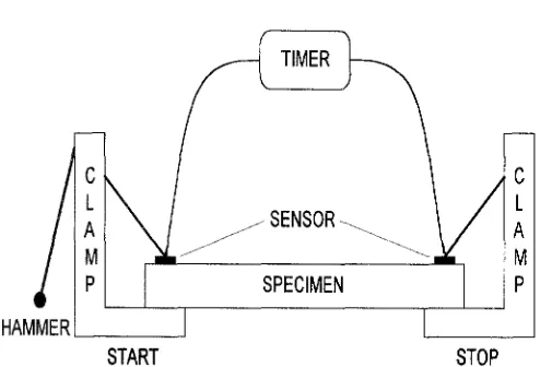
SPECIMEN
P
HAMMER
]
START
STOP
Fig. 2. Configuration for the measurement of stress wave time of lamina
M e a s u r e m e n t of M O E and M O R of glulam
The M O E and M O R of glulam were measured over a 3-m span with five-point loading. The ultimate load, propor- tional limit load, and deflection were recorded for calcula- tion of M O E and M O R of glulam.
Modification of measured M O E
sured. Based on the actual distance of this interval, the propagation velocity of the stress wave was calculated. M O E s of the 60-cm segment and the entire length were
then calculated by E q (1): 2
/
- - - (1) Eai 2 ~ Eai (2)
1 + k 2 where MOEsw is the stress wave modulus of elasticity by
stress wave time (kg/cm2), C is the stress wave propagation velocity (cm/s), D is the density of the lamina (kg/cm3), and g is the acceleration of gravity (980cm/sZ).
Static bending test
The long span M O E was measured using flatwise bending over a 3-m span with three-point loading. Localized M O E was measured on four contiguous 60-cm segments within each lamina using flatwise bending over a span of 1.8m with four-point loading (Fig. 3).
Bending test by machinery
The M O E was also measured by a grading machine. Sam- pling was carried with 15 specimens in advance, and 194 specimens were tested to measure the M O E . The M S R machine is shown in Fig. 4.
The M O E values of primary concern are apparent values E~i, used in deflection equations that attribute all deflection to moment. These apparent moduli m a y be standardized for a specific span/depth ratio and load configuration. Stan- dardization should reflect, as far as possible, conditions of anticipated end use. W h e n tests at standardized conditions of load and span are not possible, to adjust the Ea~ to stan- dardized conditions it is necessary to account for the effect of shear deflection on b e a m deflection. Factors to adjust
Eai
for the span/depth ratio and load configuration m a y be derived from Eq. 2. ~5
where h is the depth of the beam; L is the total b e a m span between supports; Ea~2 is the apparent modulus of elasticity based on any set of conditions of the span/depth ratio and load configuration; Eai is the modulus of elasticity based on another set of conditions; G is the modulus of rigidity; kl is 1.25 in this study; and k2 is 0.91 in this study.
Results and discussion
M O E of lamina
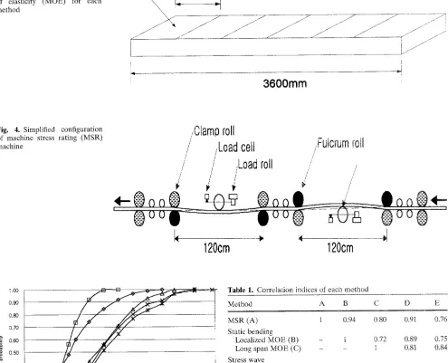
Fig. 3. Unit of localized modulus of elasticity (MOE) for each method
Localized MOE
\
~ 6 0 0 m m/ . / i
[
3600mm
Fig. 4. Simplified configuration of machine stress rating (MSR) machine
/Clamo roll
,,Fulcrum roll
/Load cell
/
/
iLoad roll
/,'
/ // /
~"
ii
120cm
120cm
1.00
0,90 S
0.80 0.70 >,
0,60 0.80 0.40
I 0.30
8 0.20
0.10 0.00
60 80 100 120 140 160 180 MOE( • 102 kg/cm 2)
--X--MSR --)E--Ioc. of sta. bend. 0 long ofsta, bend. oc. of s~. way. ~ l o n g of str. way.
Fig. 5. Cumulative probability distributions of MOE for each method
tween the long span M O E and the localized M O E t h a n the difference a m o n g the other methods. It is interesting that the result of M S R m e t h o d is similar to the localized results of each method. A l l five results were applied to the predic- tion p r o g r a m of glulam performance.
M O R of l a m i n a
T h e r e were m a n y regression equations b e t w e e n M O R and MOE.l213'16 Most equations were based on the long span
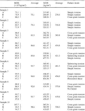
Table 1. Correlation indices of eac~ method
Method A B C D E
MSR (A) 1 0.94 0.80 0.91 0.76
Static bending
Localized MOE (B) - 1 0.72 0.89 0.75
Long span MOE (C) - - 1 0.81 0.84
Stress wave
Localized MOE (D) - - - 1 0.76
Long span MOE (E) - - - 1
MSR, machine stress rating; MOE, modulus of elasticity
test. A l t h o u g h there were problems with the long span test, the M O R s of l a m i n a were calculated using Eq. 3 without m e a s u r e m e n t , because l a m i n a must b e e n used w h e n m a n u - facturing glulam.
M O R = 4.78 x 10 -3 x M O E + 0.2 (3)
E q u a t i o n 3 is the regression e q u a t i o n reported by H a s h i z u m e et al. 16 These predicted M O R s of l a m i n a were used as i n p u t variables to predict glulam M O R .
M O E and M O R of glulam
Table 2. Bending test results for MOE and MOR of glulam
MOE Average MOR Average Failure mode ( • 103 kg/cm 2) (kg/cm 2 )
Sample 1
A 73,1 }
B 71.9 75.1 C 80.2
Sample 2
A 83.5 }
B 82.5 79.3 C 71.9
Sample 3
A 88.4 }
B 76.3 83.3 C 85.3
Sample 4
A 86.2 }
B 88.3 86.8 C 85.9
Sample 5
A 83.8 }
B 85.8 85.8 C 87.9
Sample 6
A 91.8 }
B 98.3 93.7 C 91.1
Sample 7
A 95.9 }
B 97.3 96.8 C 97.2
Sample 8
A 88.4 }
B 86.9 92.8 C 103.0
Sample 9
A 93.7 }
B 89.7 93.7 C 97.8
Sample 10
A 107.7 }
B 93.5 98.6 C 94.5
313.60 ] Simple tension 246.05 I 276.0 Simple tension 268.24 Cross grain tension 300.63 ~ Simple tension 326.84 / 316.0 Simple tension 320.52 Simple tension 362.76 ) Cross grain tension 290.98 / 365.8 Simple tension 443.55 Cross grain tension 441.45 ] Simple tension 401.47 I 454.8 Simple tension 521.41 Cross grain tension 339.84 ] Cross grain tension 445.96 I 4 2 1 . 2 Splintering tension 477.72 Simple tension 565.40 ] Splintering tension 525.92 I 481.5 Cross grain tension 353.13 Simple tension 406.45 ] Simple tension 520.99 I 454.0 Cross grain tension 434.56 Horizontal shear 315.89 / Cross grain tension 434.14 I 375.0 Simple tension - Not failed 422.55 1 Cross grain tension 376.70 I 419.6 Cross grain tension 459.65 Simple tension 587.34 ~ Cross grain tension 583.99 / 530.3 Simple tension 419.65 Cross grain tension MOR, modulus of resistance
119
mostly developed in the vicinity of the k n o t area, and prin- cipal failure m o d e s were simple tension m o d e and cross- grain tension mode. G r o w t h defect factors, such as knot and grain deviation, had m o r e effect on failure d e v e l o p m e n t than the strength factors, such as M O R and M O E . There- fore, although the M S R result is economical and less time- consuming for glulam manufacturing of main structural m e m b e r s that require special attention, caution must also be considered for visual grading results, which could reflect detailed growth defects of m e m b e r s . E v e n if similar grade laminas are used for manufacturing glulam, growth defects must be avoided next to the loaded area.
Figure 6 shows the predicted M O R s and m e a s u r e d M O R s of glulam. T h e results in Fig. 6 show that the pre- dicted M O R of glulam was highly sensitive to the M O E of lamina. Therefore, the M O E of lamina can be used as an input variable to predict the M O R of glulam.
55O ~-- 5O0
o
E 4 5 0 - - 4 0 0 3 5 0 3 0 0 - - 2 5 0 2 0 0 ...
7O
i ) ]
L + I I I -J
75 80 85 90 95 1 O0
MOE(X 103 kg/cm 2) [o MOB of glulaml
0.80 ,, 0.70 =
0.60 ~_ 0.5O "~ 0.4O
0.30
8 0.m
0.10 0.00
55 75 95 115 135
MOE( X 10 a k g / c m 2)
[
--e--Ioc. ofstr, wav. n Ioc. ofsta, bend. A Iongofsta. bend.
I--x--long of str.wav, x MSR O Experimental resul
Fig. 7. Comparison of simulated results and actual test results for M O E of glulam (input variable is the M O E of lamina for stress wave test)
Table 3. Correlation matrix of M O E for each method
Test MSR Static Stress Actual
test bending wave test test
test
MSR 1 0.85 0.87 0.95
Static bending - 1 0.90 0.91
Stress wave - - 1 0.92
Actual - - - 1
Table 4. Correlation matrix of M O R for each me~hod
Test MSR Static Stress Actual
test bending wave test test
test
MSR 1 0.81 0.82 0.87
Static bending - 1 0.79 0.85
Stress wave - - I 0.90
Actual - - - i
1.0 0.9 0.8 ,, 0.7 0.6
g
~ 0.5 .~ 0.4 =~0.3
o 0.2
0.1
jfA m'
1 7
3OO 4OO 5OO
M O R ( k g / c m 2 )
200 600 700
o Ioc. ofsta, bend. .--lr,--Iong ofsta, bend. O Experimental result
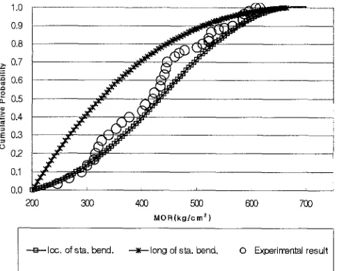
Fig. 8. Comparison of simulated results and actual test results for M O R of glulam (input variable is the M O E of lamina for stress wave test)
Comparison of simulated and actual test results
Figures 7 and 8 show the cumulative probability distribution between simulated results and actual test results of the 6- Lam Japanese larch glulam beam. For all five input vari- ables the simulated M O E and M O R of glulam were in close agreement with the actual test results, but there was a small difference between the predicted values depending on the results of the long span tests and the localized tests. This difference may be based on the hypothesis that localized properties more often reflect the detailed local strength- reducing factor of a member than long span properties, but more research is needed to make it clear. Also, according to previous research results, the mechanical properties of the lumber exhibit significant variability within individual pieces as well as between pieces.
Using the results of localized tests shows excellent corre= lation, rather than using those derived by the long span test. When the MSR result was used as an input variable, the most approximate result was obtained. Therefore, it is be- lieved that the MSR test results as input data are adequate to predict the strength of gtulam. MSR is the most economi- cal and involves little loss of measurement time; it is also appropriate to process automation among each evaluation i method to determine the strength of lamina.
Tables 3 and 4 show the correlation indices among actual test results and MSR results, localized static bending results,
I
i and localized stress wave results.
Conclusions
Based on the results of the strength test of lamina, there was a more segnificant difference between the long span M O E and the localized M O E than among the other testing meth- ods. All five input variables were applied in the strength prediction study to compare the actual results and the pre- dicted results. There was a little difference between the predicted values depending on the results of the long span tests and the localized tests. When predicting the M O E and M O R of glulam, the results using the localized M O E of lamina showed better correlation rather than those using the long span M O E of lamina.
Acknowledgments The work was supported financially in part by the 1995 specific research project of the Ministry of Agriculture and For- estry and Fishery, Korea.
References
2. Kline DE, Woeste FE (1986) Stochastic model for modulus of elasticity of lumber. Wood Fiber Sci 18:228-238
3. Burk AG, Bender D A (1989) Simulating finger-joint performance based on lacalized constituent lumber properties. For Prod J 39(3):45-50
4. Ehlbeck J, Cooling F, Gorlacher R (1985) Einfluss keilgezinkter lamellen auf die Biegefestigkeit von brettschichtholztragern- Entwichkungeines Rechenmodells. Holz Als Roh Werkstoff 43:333-337
5. Ehlbeck J, Cooling F, Gorlacher R (1985) Einfluss keilgezinkter lamellen auf die Biegefestigkeit yon brettschichtholztragern- Eingangsdaten f[xr das Rechenmodell. Holz Als Roh Werkstoff 43:369-373
6. Cooling F (1990) Biegefestigkeit von Brettschichtholztr~gern in Abhangigkeit von den festigkentsrelevanten Einfluss gr~ssen- Entwicklung eines statistischen Modells. Holz Als Rob Werkstoff 48:269-273
7. Hernandez R, Bender DA, Richburg BA, Kline KS (1992) Probablistic modeling of glued-laminated timber beams. Wood Fiber Sci 24:294-306
8. Hernandez R (1993) Probablistic modeling of yellow poplar glued- laminated timber. FPL no. 93-4534
9. Yeh B (1996) Using computer models to predict the performance of structural glued laminated timber. Int Wood Eng Conf 96 1:136- 143
10. Foschi RO, Barrett JD (1980) Glued laminated beam strength. J Struct Div ASCE 106:1735-1754
11. Foschi RO (1987) A procedure for the determination of localized modulus of elasticity. Holz Als Roh Werkstoff 45:257-260 12. Pellicane PJ (1994) Finite element analysis of finger-joints in lum-
ber with dissimilar laminate stiffness. For Prod J 44(3):17-22 13. Taylo SE, Bender D A (1991) Stochastic model for lacalized tensile
strength and modulus of elasticity properties in lumber. Wood Fiber Sci 23:501-519
14. American Society for Testing and Materials (1995) Test method for establishing stresses for structural glued-laminated timber. ASTM D 3737-93c. American Society for Testing and Materials, Philadelphia, PA
15. American Society for Testing and Materials (1995) Standard prac- tice for evaluating allowable properties for grades of structural lumber. ASTM D 2915-94. American Society for Testing and Ma- terials, Philadelphia, PA
16. Hashizume T, Yoshida T, Takeda T, Ishihara S (1998) Properties of laminae from a planted Japanese larch tree, and the mechanical proPerties of glued laminated timber IV. Mokuzai Gakkaishi 44:49-58