www.mech-sci.net/4/345/2013/ doi:10.5194/ms-4-345-2013
©Author(s) 2013. CC Attribution 3.0 License.
Mechanical
Sciences
Open AccessNew empirical stiffness equations for
corner-filleted flexure hinges
Q. Meng1, Y. Li1,2, and J. Xu1
1Department of Electromechanical Engineering, Faculty of Science and Technology, University of Macau, Av. Padre Tomas Pereira, Taipa, Macao SAR, China
2School of Mechanical Engineering, Tianjin University of Technology, Tianjin 300384, China
Correspondence to: Y. Li ([email protected])
Received: 6 March 2013 – Revised: 13 May 2013 – Accepted: 5 June 2013 – Published: 15 October 2013
Abstract. This paper investigates the existing stiffness equations for corner-filleted flexure hinges. Three empirical stiffness equations for corner-filleted flexure hinges (each fillet radius, r, equals to 0.1 l; l, the length of a corner-filleted flexure hinge) are formulated based on finite element analysis results for the purpose of overcoming these investigated limitations. Three comparisons made with the existing compliance/stiffness equations and finite element analysis (FEA) results indicate that the proposed empirical stiffness equations enlarge the range of rate of thickness (t, the minimum thickness of a corner-filleted flexure hinge) to length (l),
t/l (0.02≤t/l≤1) and ensure the accuracy for each empirical stiffness equation under large deformation. The errors are within 6 % when compared to FEA results.
1 Introduction
Flexure-based compliant mechanisms (FCMs) are becoming increasingly popular due to their remarkable advantages such as part-count reduction, reduced assembly time, and simpli-fied manufacturing processes in terms of cost reduction, in-creased precision and reliability, reduced wear and weight, and increased performance (Palmieri et al., 2012; Lobontiu, 2002; Berselli, 2009). In addition, FCMs are the perfect sub-stitutions of traditional rigid mechanisms, compared to the other types of compliant mechanisms. A FCM can not only transform a traditional rigid mechanism in terms of its func-tions and structure, but also implement high precision and high frequency while the traditional rigid mechanism cannot do. For instance, FCMs are increasingly used in the fields of micro-scale and nano-scale technologies, such as smaller and high precision positioning devices in automobiles, telecom-munications, medical, biology, optics or computer industries (Ma et al., 2006; Ivanov and Corves, 2010; Yin and Anantha-suresh, 2003; Lobontiu and Garcia, 2003; Dong et al., 2008, 2005; Xu and King, 1996; Li and Xu, 2009).
A FCM relies on the elastic deformation of its connectors, i.e. the flexure hinges, to perform its functions of transmit-ting and/or transforming motion and force (Yin and
Figure 1.Corner-filleted flexure hinge (a), circular flexure hinge (b) and elliptical flexure hinge (c).
hinges, elliptical flexure hinges and corner-filleted flexure hinges as shown in Fig. 1 are commonly used in FCMs be-cause they are simple and easy to control (Smith et al., 1997; Yong et al., 2008).
This paper addresses the corner-filleted flexure hinges. The stiffness characteristics of corner-filleted flexure hinges with a wide range of t/l are analyzed under different loads applied at the free-end. The influence introduced by shear-ing is taken into account durshear-ing the whole analysis. Different ratios t/l are investigated in order to overcome the influence induced by shearing.
The remaining sections of this paper are organized as follows. Section 2 summarizes simply existing research re-sults and some problems need to be resolved in future about corner-filleted flexure hinges. In Sect. 3, fifty finite element analysis models of corner-filleted flexure hinges are built up and their static plane stress analysis is simulated. In Sect. 4, three stiffness empirical equations are formulated by fitting the FEA results. A comparison of the new results together with the previous results is made to FEA in Sect. 5. In the end, the conclusions are drawn in Sect. 7.
2 Literature review
It can be dated back to 1965, Paros and Weisbord firstly pre-sented the compliance-based approach to symmetric circu-lar and right circucircu-lar flexure hinges by giving the compli-ance equations and the approximate engineering formulas for these flexure hinges. The analytical approach of mono-lithic flexure hinges is the landmark in the research of flex-ure hinges. Particularly, the angles and linear deflections pro-duced on all three axes are expressed in terms of the corre-sponding external loading.
Ragulskis et al. (1989) analyzed the filleted flexure hinges by applying the static finite element analysis method in order to calculate their compliances (Lobontiu et al., 2001).
In the early work of Howell and Midha (1994), they pre-sented a computer-aided design method to pseudo-rigid-body model that included short length beam. A short length beam can be considered as a corner-filleted flexure hinges without filleted corners at the junction of flexible part and rigid part.
In 1996, Xu and King utilized the topology method to de-sign a flexure-based amplifier for piezo-actuators. Right cir-cular, corner-filleted, and elliptical flexure hinges were an-alyzed by static finite element analysis (FEA) method. By
comparing both the FEA models to the traditional right-circular flexure hinges, three useful points were presented in their conclusions. They revealed that the corner-filleted flex-ure hinges are the most accurate in terms of motions relative to the elliptical flexure hinges, the elliptical flexure hinges have less stress for the same displacement and right circular flexure hinges are the stiffest. It is worth to note that the mo-tion described here does not mean the precision of rotamo-tion. Even though the corner-filleted flexure hinges provide more accuracy on motion than the elliptical flexure hinges, they present less precision in terms of rotation. The deviation of the rotation center point of a corner-filleted flexure hinges is bigger than a circular flexure hinge.
planar compliant mechanisms with single-axis flexure hinges relying on the strain energy and Castigliano’s displacement theorem. Specifically, circular flexure hinges and corner-filleted flexure hinges as typical symmetric single-axis flex-ure hinges are contained in the amplifiers in order to verify the deduced stiffness equations.
Du et al. (2011) proposed that a new class of flexure hinges named elliptical-arc-fillet flexure hinges, which covers ellip-tical arc, circular-arc-fillet, ellipellip-tical-fillet, ellipellip-tical, circular, circular-fillet (in the other words, corner-filleted, the major axis equals to the minor axis of the elliptical arc), and right circular flexure hinges together under one set of equations. The closed-form equations for compliance and precision matrices of elliptical-arc-fillet flexure hinges were derived in their works. In consequence, the analytical results were within 10 % error compared to the FEA results and within 8 % error compared to the experimental results. It is worth to note that the closed-form equations were derived based on the small-deformation theory. Therefore, these equations can be valid only when the deformations of the flexure hinges are small enough, or the thickness t to length l ratios are small enough (Du et al., 2011).
With the development of FCMs, the refined design equa-tions under small deflecequa-tions for typical flexure hinges cannot meet the needs of designers. Large deformation started to be a key problem to develop the typical flexure hinges. Never-theless, the stiffness characteristics of flexure hinges under large deformation are complex due to shearing deformation. Scholars seek to stay away from the problem in the research. For instance, Trease et al. (2005) proposed a new compli-ant translational joint in order to overcome the drawbacks of typical flexure hinges such as limited range of motion, axis drift and off-axis stiffness. Compared with the typical flexure hinges, however, the new designed joint is complex. Howell (2002) studied short slender beams under large deformation due to a force or a moment on its free-end. The length of the short beam should be much shorter than the length of the rigid part, while the flexible part should be more compli-ant than the rigid part. It signifies that the thickness of the short beam should be much less than its length (t/l≤0.1) (as shown in Fig. 1a).
Tian et al. presented a dimensionless design graph for cir-cular, corner-filleted and cross flexure hinges, based on finite element analysis. The maximum stiffness properties from different hinges in identical situations were described by the FEA results. It revealed that a corner-filleted flexure hinge is preferred over a circular flexure hinge for stiffness demands in a single direction, while the medium stiffness is a cross flexure hinge (Qin et al., 2013; Tian et al., 2010b).
In real applications, however, the existed research results cannot meet some requirements such as stiffness and struc-ture magnitude (the different ratio t/l) determination. Meng et al. (2012) studied the corner-filleted flexure hinges by syn-thesizing each kind of situation, i.e. the different ratio t/l
and large deformation, under only a pure moment on the free-end.
From the previous works, it can be noted that there are no more accurate design formulas at the stage to estimate stiff -ness/compliances in the x and y directions for t/l≥0.1 and the rotational stiffness equation for a vertical force applied at the free end. Therefore, general empirical stiffness equations (named Kθ, Kxand Ky) are formulated in the Sect. 4 based
on FEA results to evaluate the stiffness in x and y directions for a wide range of t/l ratios. Also, the rotational empirical stiffness equation will be presented in this section.
3 FEA modeling of corner-filleted flexure hinge
According to the descriptions aforementioned, there are three basic research approaches to the flexure hinges. The first one is based on displacement theorem, the second one is the pseudo rigid body model (PRBM), and the last one is the finite element analysis method. FEA method is used as a benchmark for calculating the rotational stiffness and the stiffness in the x and y directions for flexures. Also, FEA is an important approach to verify these formulas proposed based on the first two research methods. The accuracy of these FEA models was verified by Lobontiu and was with the maximum 8 % error compared to three experimental results (Lobontiu et al., 2004). Therefore, this paper studies the stiffness char-acteristics for corner-filleted flexure hinge with a wide range of t/l under large deformation by means of FEA.
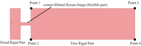
Figure 2.An analytical corner-filleted flexure hinge model.
deformation of this part. On the other hand, the free rigid part should keep it rigid in order to ensure the accuracy of the re-sults. Therefore, the FEA models were designed with a short rigid part at the fixed end and a long rigid part of the fore-end as shown in Fig. 2. The research of corner-filleted flex-ure hinges under a pflex-ure moment applied at the free-end was presented in the previous work. This paper studies corner-filleted flexure hinges under a force in the x or y direction. It is well known that the accuracy of the FEA results can also be influenced by the way the point conditions are assigned to the model. For instance, when a point force in the y direction is applied at the end point of the whole model, an extra mo-ment can be produced in terms of the rotational center point. As for the position where force is applied in the y direction, in this paper, a couple of forces are loaded at the point 1 and point 2, respectively, as shown in Fig. 2. While as for the position where force loaded in the x direction, a couple of forces are applied at the point 3 and point 4. Such loading method can decrease the FEA results error.
4 Empirical stiffness/compliance equations
From the previous section, FEA models with different t/l ratios, which were set from 0.02 to 1 with an increment of 0.02, were generated in COMSOL software. Forces in terms of Fx and Fy were applied at each model and the
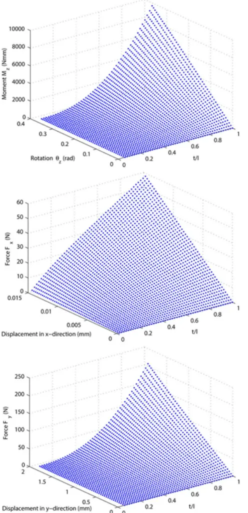
corre-sponding deformations, δx and δy were read. Figure 4a, b and c, which shows the relationship between the applied force, the deformation/deflection, and the rate of t/l, indi-cates that the stiffness is increasing with the increasing defor-mation/deflection and the increasing geometric parameter t/l. According to the compliance/stiffness equations calculated based on the Castiliagno’s displacement theorem (Lobontiu, 2002), the Young’s modulus, E, and the width of hinge, w, are proportional to the stiffness around z axis and in x, y di-rections. Therefore, the product of the two parameters can be divided. Such this, the stiffness can be transformed into a dimensionless quantity. The dimensionless design approach is very popular in the design of FCMs. In addition, the ra-tio of height to length, t/l, is an important parameter to the stiffness.
Figure 3.FEA meshing.
4.1 Empirical rotational stiffness equation
The rotational stiffness for corner-filleted here is under the condition of a perpendicular force applied at the end. Ac-cording to the data in terms of δx and δy read from FEA results, the rotational angles were calculated by means of de-forming geometric relationship. The data shown in Fig. 4a is rearranged for stiffness characteristic and the relationship is about rotational stiffness dimensionless design parameter (Kθ/Ew) and the rate t/l as shown in Fig. 5.
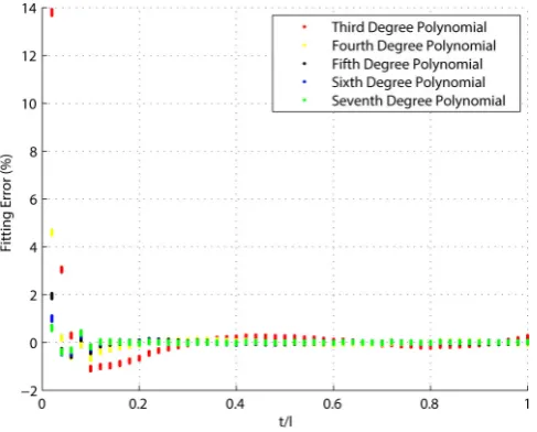
It is easy to figure out that the dimensionless design pa-rameter is nearly a function of the rate t/l. While the devi-ation lies at the end of the reldevi-ationship curve indicates that the stiffness is related to the deformation. The fourth poly-nomial, the fifth polypoly-nomial, and the sixth polynomial func-tions were fitted with fitting target of the norm of the residu-als, 0.61475,0.61323,0.61321, respectively, by means of the data points to formulate empirical rotational stiffness equa-tions. The fitting errors of these fitting functions are shown in Fig. 6. It can be observed from the figure that the minimum fitting error is produced by the sixth polynomial fitting tion. The maximum fitting error produced by this fitting func-tion is 2.3474 %. In consequence, the sixth polynomial fitting function is chosen as the rotational stiffness design equation as shown in Eq. (1) and its coefficients are shown in Table 1.
Kθ Ew=
6 X
i=0 ai
t
l
i
(1)
It is worth to mention that the maximum rotational angle of these FEA models during their deforming is 23◦. It means that the influence about shearing deformation was taken into account in the empirical stiffness equation.
4.2 Empirical stiffness equation inxdirection
By following the similar procedure as the rotational stiffness, the relationship between the dimensionless design parameter for stiffness in x direction, K−x/Ew, and the rate t/l is shown
in Fig. 7.
Figure 4.(a) The relationship between Mz, t/l, and rotation angle,
θz; (b) The relationship between Fx, t/l, and displacement in x
di-rection; (c) The relationship between Fy, t/l, and displacement in
y direction.
polynomial function and the maximum fitting error produced by this function is 0.7213 %. Consequently, the seventh de-gree polynomial function is chosen as the dimensionless stiff -ness design equation as shown in Eq. (2) and its coefficients are listed in Table 1.
Figure 5.Rotational stiffness dimensionless design parameter.
Figure 6.Fitting errors.
Kx Ew=
7 X
i=0 bi
t
l
i
(2)
4.3 Empirical stiffness equation inydirection
Figure 4c is rearranged for stiffness equation in y direction as shown in Fig. 9. It can be found from this figure that the dimensionless design stiffness parameter Ky/Ew also can be considered as a function of the rate t/l.
Figure 7.Stiffness in x direction dimensionless design parameter.
Figure 8.Fitting errors.
was chosen at first. The fourth, fifth, sixth degree polyno-mial function was fitted with the fitting target of the norm of the residuals, 0.0064273, 0.0064261, and 0.0064261, respec-tively. The fitting errors are shown in Fig. 10 that shows the minimum errors were produced by the sixth degree polyno-mial function and the maximum error is 5.2914 %. Therefore, as for the simple fitting function, the sixth degree polynomial function is chosen as the dimensionless stiffness in y direc-tion design equadirec-tion as shown in Eq. (3) and its coefficients are listed in Table 1.
Ky Ew=
6 X
i=0 ci
t
l
i
(3)
In order to obtain more accurate fitting stiffness equations, the displacementδyis taken into account. By following the
Figure 9.Stiffness in y direction dimensionless design parameter.
Figure 10.Fitting errors.
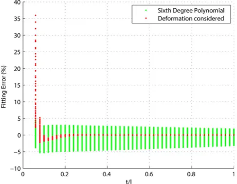
procedure mentioned above, the fitting equation is shown in Eq. (4) and its coefficients are listed in Table 1. Figure 11 shows the fitting error together with the fitting error produced by the simple fitting equation. It shows that the maximum error produced by the complex one is 1.8233 % when the rate
t/l is larger than 0.08, while the error is much larger than
the one produced by simple fitting equation when the rate t/l is smaller than 0.08. Therefore, the designer can choose the design equation according to the design rate t/l.
Kcy Ew=
5 X
i,j=0 µi jt
l
i
(∆y)j, j≤2 (4)
Figure 11.Fitting errors.
5 Comparison of compliance/stiffness results with
the previous work and FEA
From Sect. 2, there are a lot of researches in the study of compliance/stiffness characteristics for corner-filleted flex-ure hinges. This paper adopts the stiffness/compliance equa-tions proposed by Howell (2002), Lobontiu (2002), Du et al. (2011) and Meng et al. (2012) in order to compare to the new empirical stiffness equation. Howell and Midha (1994) proposed stiffness equations for slender beam (it can be considered as a corner-filleted flexure hinge without fil-leted corners) by means of the pseudo rigid body model. The thickness-length ratio (t/l) is limited to less than 0.1. How-ever, the deflection is not limited. Lobontiu proposed com-pliance equations by integrating the linear differential equa-tion of a beam. The thickness-length ratio has not been lim-ited. But the deformation must be small. Du et al. (2011) derived the compliance equations based on matrix methods. These closed-form compliance equations for the special con-figuration which is circular-fillet flexure hinges can be uti-lized when the thickness(t)-length(l) ratio is less than 0.1. Stiffness equations proposed by Meng et al. (2012) are fit-ted by means of FEA results based on Lobontiu’s equations. Full stiffness equation and simple stiffness equation can be valid even though the deformation is large. However, it is noticed that the loading approach for equations of Howell (2002) and Meng et al. (2012) is a pure moment applied at the end. Therefore, these equations cannot describe the ro-tational stiffness accurately when a vertical force is applied at the free-end. These stiffness equations are shown in Ap-pendix A, B, C and D.
Table 1.Coefficients for Eqs. (1), (2), (3), and (4).
Eq. (1) Eq. (2) Eq. (3)
a0 6.10E-04 b0 1.64E-03 c0 −1.60E-03
a1 −1.87E-02 b1 1.02E+00 c1 7.78E-03
a2 2.25E-01 b2 −1.11E+00 c2 −1.85E-02
a3 7.42E+00 b3 2.28E+00 c3 3.00E-02
a4 −4.57E+00 b4 −3.61E+00 c4 8.28E-04
a5 2.11E+00 b5 3.75E+00 c5 −6.27E-05
a6 −4.59E-01 b6 −2.17E+00 c6 1.92E-06
b7 5.27E-01
Eq. (4)
µ00 1.10E-05 µ12 −1.13E-02 µ31 8.71E-03
µ01 −1.28E-04 µ20 1.94E-03 µ32 −1.39E-02
µ02 7.63E-04 µ21 −6.77E-03 µ40 −1.18E-02
µ10 −2.35E-04 µ22 5.02E-02 µ41 −3.80E-03
µ11 1.75E-03 µ30 2.55E-02 µ50 2.67E-03
5.1 Comparison of rotational stiffness equations,Mz/θz
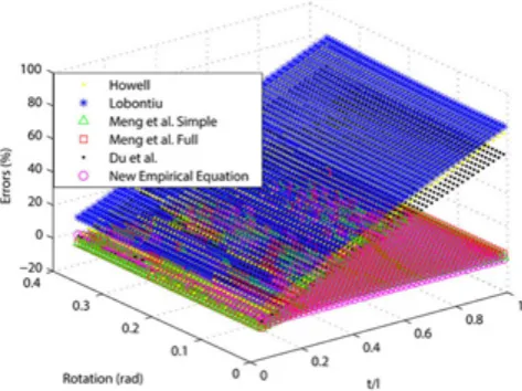
Stiffness, Mz/θz (or its inverse, compliance, θz/Mz) of the corner-filleted flexure hinge as mentioned before was calcu-lated using design equations of Lobontiu (2002), Howell and Midha (1994), Du et al. (2011), full and simple equation of Meng et al. (2012) and the new empirical equation. Their re-sults were compared with the FEA rere-sults by the simulation method used in this paper. A corner-filleted flexure hinge, which was with thickness-length ratio t/l equaled to 0.5 and the maximum deforming rotational angle equaled to 23◦, is chosen as an instance in order to show the errors induced by these equations. The comparison results are shown in Fig. 12. It shows that the results calculated by the equation of How-ell (2002) and Lobontiu diverged greatly from the FEA re-sults. The maximum errors induced by the equation of How-ell (2002) and Lobontiu were 40.2252 % and 45.787 %, re-spectively, happened on the maximum rotation. The error in-duced by the compliance equation of Du et al. (2011) is less than Howell’s and Lobontiu’s, and it is 32.57 %. However, the errors induced by full and simple stiffness equations de-duced by Meng et al. (2012) are small, and the maximum er-rors are 3.3292 % and 3.6826 %, respectively. The minimum error is produced by the new empirical rotational stiffness equation and it is only 0.7955 % at the identical situation.
Figure 12.Comparison between FEA results and stiffness equa-tions results t/l=0.5.
Figure 13.Errors of comparison results.
new one. The maximum errors induced by these equations of Howell (2002), Lobontiu (2002), Du et al. (2011), Meng et al. (2012) full and simple, and new empiric are 79.3530 %, 83.3920 %, 66.3578 %, 3.7248 %, 3.3292 %, and 2.2474 %, respectively.
5.2 Comparison of stiffness equations inxdirection,
Fx/δx
According to the previous comparison approach, the stiff -ness in x direction, Fx/δxof the corner-filleted flexure hinge was calculated using design equations of Lobontiu, Du et al. (2011) and new empirical stiffness equation. Their re-sults were compared with the FEA rere-sults by the simula-tion method used in this paper. As what’s described above, the corner-filleted flexure hinge, which was with
thickness-Figure 14.Comparison between FEA results and stiffness equa-tions results t/l=0.5.
length ratio t/l being 0.5 and the maximum displacement in
x direction being 0.0147 mm, was chosen as an instance in
order to show the errors induced by these equations. The comparison results are shown in Fig. 14. We can observe that the results calculated by the equations of Lonbontiu and Du et al. (2011) diverged greatly from the FEA results. The maximum error induced by the equation of Lobontiu (2002) and Du et al. (2011) were 32.3346 % and 32.1432, respec-tively, happened on the maximum displacement. However, the new empirical rotational stiffness equation produced only 0.0763 % at the identical situation.
Percentage errors of the comparison for various ratios of thickness-length are plotted in Fig. 15. The figure shows that the equations of Lobontiu and Du et al. (2011) only keeps ac-curate when the ratio of thickness to length is small enough. However, the results calculated by the new empirical stiffness equation in x direction have not diverged too much from the FEA results. The maximum errors induced by these equa-tions of Lobontiu, Du et al. (2011), and new empirical are 45.2946 %, 45.0941 %, 0.7213 %, respectively.
5.3 Comparison of stiffness equations inydirection,
Fy/δy
The stiffness in y direction, Fy/δyof the corner-filleted
Figure 15.Errors of comparison results.
Figure 16.Comparison between FEA results and stiffness equa-tions results t/l=0.5.
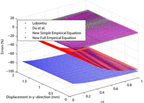
Fig. 16. We can see that the results calculated by equa-tion of Lobontiu (2002) and Du et al. (2011) deviate greatly from the FEA results. The maximum error induced by the equation of Lobontiu and Du et al. (2011) were 84.3457 % and 61.2894 %, respectively, happened on the maximum dis-placement. However, the new empirical rotational stiffness equations produced only 2.49 % and 0.0622 %, respectively, at the identical position.
Percentage errors of the comparison for various ratios of thickness-length were plotted in Fig. 17. The figure shows that the equation of Lobontiu and Du et al. (2011) were not accurate whenever the ratio of thickness to length is small or large. However, the results calculated by the new empir-ical stiffness equation in y direction have not deviated too much from the FEA results. The maximum errors induced
Figure 17.Errors of comparison results.
by these equations of Lobontiu, and new empirical equations are 87.1453 %, 82.8926 %, 5.2914 %, and 1.8233 %, respec-tively. The errors induced by equations of Lobontiu existed because that the shear compliances/stiffness were not consid-ered in the compliance equations.
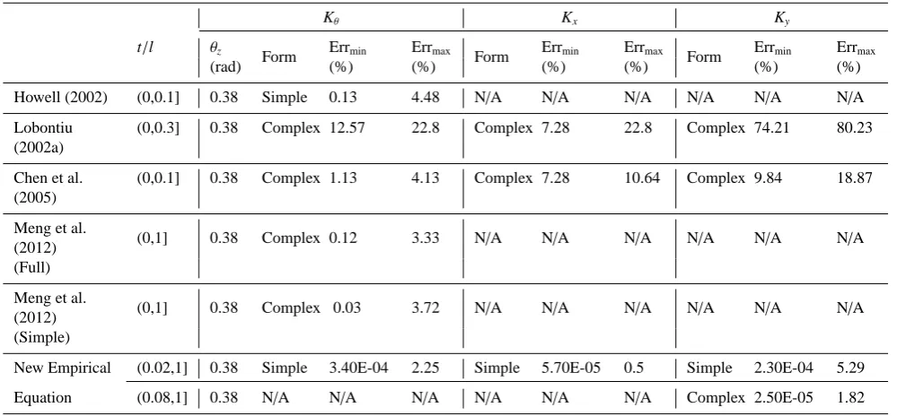
To sum up, the suggested stiffness/compliances equations to be used for any particular t/l range and the correspond-ing minimum, maximum percent errors, were summarized in Table 2.
6 Conclusions
Howell (2002) (0,0.1] 0.38 Simple 0.13 4.48 N/A N/A N/A N/A N/A N/A
Lobontiu (2002a)
(0,0.3] 0.38 Complex 12.57 22.8 Complex 7.28 22.8 Complex 74.21 80.23
Chen et al. (2005)
(0,0.1] 0.38 Complex 1.13 4.13 Complex 7.28 10.64 Complex 9.84 18.87
Meng et al.
(2012) (0,1] 0.38 Complex 0.12 3.33 N/A N/A N/A N/A N/A N/A
(Full)
Meng et al.
(2012) (0,1] 0.38 Complex 0.03 3.72 N/A N/A N/A N/A N/A N/A
(Simple)
New Empirical (0.02,1] 0.38 Simple 3.40E-04 2.25 Simple 5.70E-05 0.5 Simple 2.30E-04 5.29
Equation (0.08,1] 0.38 N/A N/A N/A N/A N/A N/A Complex 2.50E-05 1.82
Appendix A
Du et al.
Compliance equation in x, y andαzdirection
∆x Fx =
a EwbN1+
l Ewt
∆y
Fy =Gwbka N1+6L
2a−12a(cl+c2−a2)
Ewb3 N2
−12a3
Ewb3N4+
24a2l Ewb3N6+
kl Gwt
+6L2l−2l(l2+6c2+6cl)
Ewt3
∆αz Mz =
12a
Ewb3N2+ 12l
Ewt3 where,
N1=
2(2s+1)
√
4s+1 arctan
√
4s+1 tanφm 2
−φm
N2=12s
4(2s+1) (4s+1)5/2 arctan
√
4s+1 tanφm 2
+2s3(2s+1)(6s2+4s+1) sinφm
(4s+1)2(1+2s−2s cosφm)2
−2s
4(12s2+4s+1) sinφ mcosφm
(4s+1)2(1+2s−2s cosφm)2
N4=48s
5+8s4+20s3+30s2+10s+1 2(4s+1)5/2
×arctan(√4s+1 tanφm 2)
−[s(2s+1)
2(12s3−12s2−3s) cosφm 2(4s+1)2(2s+1−2s cosφm)2 + −12s3+2s2+6s+1
2(4s+1)2(2s+1−2s cosφm)2
]
×sinφm− φm
4
N6=
s3(cosφm−1)[(2s+1) cosφm−2s−1] 2(2s+1−2s cosφm)2
Appendix B
Howell et al.
– Rotational stiffness equation
KH=Ewt12l3
Appendix C
Lobontiu
– Compliance equation in x direction
Cx,L=Ew1
l−2r
t +
2 (2r√ +t) t(4r+t) arctan
q
1+4rt −π2
– Rotational compliance equation
Cθz,L=
12
Ewt3
(
l−2r+ 2r
(2r+t) (4r+t)3
h
t (4r+t)6r2+4rt+t2 + 6r(2r+t)2√t (4r+t) arctan
q 1+4rt
– Compliance equation in y direction
Cy,L=Ew3 {4 (l−2r)
l2−lr+r2
3t3
+√t (4r+t)h−80r4+24r3t+8 (3+2π) r2t2+ 4 (1+2π) rt3+πt4i
/4pt5(4r+t)5
+(2r+t)
3(6r2−4rt−t2)arctan r
1+4r t
√
t5(4r+t)5 +h
−40r4+8lr2(2r−t)+12r3t+4 (3+2π) r2t2
+2 (1+2π) rt3+πt4 2
/2t2(4r+t)2
+4l
2r
6r2+4rt+t2 t2(2r+t) (4r+t)2 −
(2r+t)h−24(l−r)2r2−8r3t+14r2t2+8rt3+t4i
√
t5(4r+t)5
arctan q
1+4rt }
Appendix D
Meng et al.
– Full rotational compliance equation
ΓFull= 3 X
i,j=0 ui jθi
z h L
!j
where ui j=0 if i+j≥4
KM,Full= ΓFullKθz,L
Where the coefficients ui jare shown in Table 3.
– Simple rotational compliance equation
ΓSimple= 3 X
k=0 vk h
L
!k
KM,Simple= ΓSimpleKθz,L
Where the coefficients vi jare shown in Table 3.
Table A1.Coefficients for Full and Simple Equation.
u00 1.016065 u03 −0.043752 u20 0.009576
u01 −0.680692 u10 0.002410 u21 −0.095298
u02 0.292380 u11 −0.018696 u30 −0.003720
u12 0.018095
v0 1.018856 v1 −0.713719 v2 0.350531
v3 −0.081827
Acknowledgements. This work was supported in part by Na-tional Natural Science Foundation of China (Grant No. 61128008), Macao Science and Technology Development Fund (Grant No. 016/2008/A1), Research Committee of University of Macau (Grant no. MYRG203(Y1-L4)-FST11-LYM, MYRG183(Y1-L3)FST11-LYM).
Edited by: G. Hao
Reviewed by: Y. Tian and one anonymous referee
References
Berselli, G.: On designing compliant actuators based on dielectric elastomers, University of Bologna, Ph.D. thesis, 2009.
Chen, G. M., Jia, J. Y., and Li, Z. W.: Right-circular corner-filleted flexure hinges, in: Proceedings of the IEEE International Confer-ence on Automation SciConfer-ence and Engineering, 249–253, 2005. Dong, W., Du, Z., and Sun, L.: Stiffness influence atlases of a novel
flexure hinge-based parallel mechanism with large workspace, in: IEEE/RSJ International Conference on Intelligent Robots and Systems, 856–861, 2005.
Dong, W., Sun, L., and Du, Z.: Stiffness research on a high-precision, large-workspace parallel mechanism with compliant joints, Precis. Eng., 32, 222–231, 2008.
Du, Y., Chen, G., and Liu, X.: Elliptical-arc-fillet flexure hinges: toward a generalized model for compmonly used flexure hinges, J. Mech. Design, 133, 1–9, 2011.
Howell, L. L.: Compliant Mechanisms, A Wiley-Interscience Pub-licationb, John Wiley & SONS., INC., 2002.
Howell, L. L. and Midha, A.: A method for the design of compliant mechanisms with small-length flexural pivots, J. Mech. Design, 116, 280–290, 1994.
Ivanov, I. and Corves, B.: Flexure hinge-based parallel manipulators enabling high-precision micro manipulations, Mechanisms and Machine Science, 49–60, 2012.
Li, Y. and Xu, Q.: Design and analysis of a totally decoupled flexure-based XY parallel micromanipulator, IEEE T. Robot., 25, 645–657, 2009.
Lobontiu, N.: Compliant Mechanisms: Design of Flexure Hinges, CRC Press, 2002.
Lobontiu, N. and Garcia, E.: Analytical model of displacement am-plification and stiffness optimization for a class of flexure-based compliant mechanisms, Comput. Struct., 81, 2797–2810, 2003. Lobontiu, N. and Paine, J. S. N.: Design of circular cross-section
corner-filleted flexure hinges for three-dimensional compliant mechanisms, J. Mech. Design, 124, 479–484, 2002.
Lobontiu, N., Paine, J. S. N., Garcia, E., and Goldfarb, M.: Corner-filleted flexure hinges, J. Mech. Design, 123, 346–352, 2001. Lobontiu, N., Paine, J. S. N., Garcia, E., and Goldfarb, M.:
De-sign of symmetric conic-section flexure hinges based on closed-form compliance equations, Mech. Mach. Theory, 37, 477–498, 2002a.
Meng, Q., Berselli, G., Vertechy, R., and Castelli, P. V.: An improved method for design flexure-baesd nonlinear springs, in: ASME International Design Engineering Technical Confer-ences & Computers and Information in Engineering Conference, DETC2012-70367, 2012.
Palmieri, G., Palpacelli, M., and Callegari, M.: Study of a fully com-pliant u-joint designed for minirobotics applications, J. Mech. Design, 134, 1–9, 2012.
Paros, J. M. and Weisbord, L.: How to design flexure hinges, Mach. Des., Nov., 25, 151–156,1965.
Qin, Y., Shirinzadeh, B., Zhang, D., and Tian, Y.: Compliance mod-eling and analysis of statically indeterminate symmetric flexure structures, Precis. Eng., 37, 415–424, 2013.
Ouyang, P. R., Zhang, W. J., and Gupta, M. M.: Design of a new compliant mechanical amplifier, in: ASME International Design Engineering Technical Conferences & Computers and Informa-tion in Engineering Conference, DETC2005-84371, 2005. Ragulskis, K. M., Arutunian, M. G., Kochikian, A. V., and
Pogosian, M. Z.: A Study of Fillet Type Flexure Hinges and their Optimal Design, Vibr. Eng., 3, 447–452, 1989.
of the filleted V-shaped flexure hinges for compliant mechanism designs, Precis. Eng., 34, 408–418, 2010b.
Trease, B. P., Moon, Y. M., and Kota, S.: Design of large-displacement compliant joints, J. Mech. Design, 127, 788–798, 2005.
Xu, W. and King, T.: Flexure hinges for piezoactuator displacement amplifiers: flexibility, accuracy, and stress considerations, Precis. Eng., 19, 4–10, 1996.
Yin, L. Z. and Ananthasuresh, G. K.: Design of distributed compli-ant mechanisms, Mech. Based Des. Struc., 31, 151–179, 2003. Yong, Y. K., Lu, T. F., and Handley, D. C.: Review of circular flexure
hinge design equations and derivation of empirical formulations, Precis. Eng., 32, 63–70, 2008.