Effect of Matrix Modulus, CNT Thickness,
and Interphase Volume Fraction on
Mechanical Properties of CNT-based Polymer
Composite by Finite Element Method
Shah Limon
1, Sanjit Kumer Basak
2, and A. K. M. Masud
21Department of Industrial and Manufacturing Engineering,
North Dakota State University, Fargo, ND 58102, USA
2Department of Industrial and Production Engineering,
Bangladesh University of Engineering and Technology, Dhaka 1000, Bangladesh
Abstract
-
The carbon nanotubes are well known for their superior material properties. They are effectively introducing in the composite to improve the material properties and therefore, it is necessary to understand the effect of carbon nanotubes on the mechanical properties of nanotube-based composite. In this paper, the effective Young’s modulus of the carbon nanotube-based composite is investigated by the finite element method for different matrix stiffness considering both long and short type carbon nanotubes. The effective Young’s modulus for different nanotube thickness in case of perfect bonding and interphase thickness for imperfect bonding is also determined. A 2-D axisymmetric model for the cylindrical representative volume element is considered in this work. For validation of the estimation considering the perfect bonding, finite element method results are compared with the analytical results. It is concluded that for both long and short type carbon nanotubes, the effective Young’s modulus of the composite material increases as the matrix stiffness, nanotube thickness, and interphase thickness increases.Keywords
-
Carbon nanotube, composite material, finite element method, Young’s modulus.I. INTRODUCTION
The carbon nanotubes (CNT) are well known for their remarkable properties. The CNT is discovered by Iijima in 1991 which are basically graphene sheets rolled to form tubes[1]. There are various types of CNTs depending on the direction in which the graphene sheet is rolled. The direction of the roll determined by the roll-up vector or chiral vector and the angle between chiraland unit vector is known as the chiral angle [2]. Different chiral indices and chiral angles give rise to different structured CNTssuch as zigzag, armchair, and chiral type nanotubes [2]. Further, based on wall type, CNTs are divided into two categories: single-walled nanotube (SWNT) and multi-walled nanotube (MWNT). MWNT consists of two or more concentric SWNTs held together by weak van der Waals forces. Several methods have been developed for the fabrication of CNTssuch as condensation-vaporization densation, catalytic decomposition of hydrocarbons, and heat treatment of
polymers [3].The diameter of CNTs falls under the range of 0.4 nanometers (nm) to several hundred
nmand the length ranges from several micrometers to several millimeters or even centimeter [4].
Carbon nanotubes are popular for its excellent mechanical, electrical, and thermal properties. The application of CNTs is widespread such as electronic devices, chemical sensors, reinforcement in high-performance composites, supercapacitors, and similar others [3]. Due to the potential and increasing application, many researchersare interested in properties evaluation and characterization of CNTs. The elastic modulus of SWNT is in the range of 1-5TPa (Tera Pascale) which is very high[5]. Liu and Chen proposed three representative volume elements (RVE)shape which are cylindrical, square, and hexagonal [6, 7]. They found that the stiffness of the CNT-based composite can increase 0.7 and 9.7 times for short and long CNTs, respectively, when cylindrical RVE is used at volume fractions of 2% and 5% of CNT [6]. They also claim that the stiffness of CNT-based composite is 33% more in the axial direction with long CNTs at a volume fraction of 3.6% in case of square RVE [7]. The long CNT is defined when the length of the nanotubes is same as the matrix and when nanotube length is shorter than the matrix, it is known as a short CNT-based composite. Lao et al. studied the properties of nanotube/nano clay composites [8]. The authors argued that the coiled nanotubes are better than the straight type because of their mechanical interlocking property. Qian has used continuum mechanics to investigate the mechanical behavior ofanindividual or isolated CNTs which are treated as beams, thin shells or solids in cylindrical shapes [9, 10]. It is also seen that theeffective stiffness of CNT reinforced epoxy has increased by 40% compared to the matrix at 5% by weight of the CNT [11].
interphase. The interphase can appear from several sources such as adsorbed contaminants on the fiber surface which are not adsorbed during the impregnation and cure, diffusion of chemical species, acceleration and retardation of polymerization at the interface [13, 14].Regardless of the sources, the presence of the interphase affects the properties of CNT-based polymer composites [12].For more detail on CNT-based composite, Khare and Bose [15] work is referred that reviewed the fabrication of CNTs, analyze the mechanical-electrical-thermal properties, and interfacial bonding properties of polymer and ceramic based nano-composite. Moreover, recently, Qian et al. [16] and Khan et al. [17] presented a comprehensive analysis of CNT-based polymer composite synthesis process, their properties, and various applications of the CNT-based composite material.
In this work, the effect of matrix modulus and CNT thickness on mechanical properties of the CNT-based composite is investigated considering the perfect bonding condition. The finite element method (FEM) has been used in this investigation for both long and short type CNT-based polymer composite. The case study result shows that overall composite stiffness increases for both increases of matrix modulus and CNT thickness. However, the long CNT-based composite shows a higher increase of stiffness compared to the short CNT-based composite. To validate our results, FEM estimates have been compared with the analytical results. Though most cases the finite element estimates are slightly overestimated however, the proximity and closeness of the estimates validate our results and claims. Further, the effect of the impurities also investigated in this work. Considering the impurities has a higher stiffness than the matrix, our results show that the composite stiffness also increases due to interphase impurities for both long and short CNT-based composite.
II. FINITE ELEMENT ANALYSIS
The analysis is carried out using the commercial software ANSYSand a 2-D axisymmetric FEM models are used since the RVE considered is cylindrical. The element used is 8-node quadratic ring element which is second order elements and offers better accuracy in stress analysis. Both long and short CNTs are considered. For long CNT-based composite, the length of both CNT and matrix are 100nm. For short CNT-based composite, the CNT is inside the RVE. The length of the CNT is 50nm and that of the matrix is 100nm. In order to evaluate the effective Young’s modulus of the CNT-based composite, one end of the FEM model is constrained in all directions and the other end is given a displacement, ΔL in the axial direction [7].
In order to evaluate the formula to determine the effective Young’s modulus, Ez, the CNT and matrix are considered to be homogeneous and isotropic. Since the displacement, ΔLhas been in axial direction, therefore, the strain in the Z direction is given by following equations [7],
The average stress is given by equation (3) [4],
Where A is the area of the end surface.The average stress is evaluated using the software ANSYSand then using it in equation (2) the effective Young’s modulus is determined as the strainΔL/L is a known value. In order to evaluate the average stress, the mid-plane of the model is used.
III.
ANALYTICAL METHODThe rule of mixture (ROM) based on the strength of materials theory is used to determine the effective Young’s modulus in case of long CNT. The volume fraction for long CNT is given by equation (4) [7],
Where ri and ro are the inner and outer radii of CNT and R is the outer radius of the matrix.The effective Young’s modulus in the axial direction is [7],
Where Et and Em are Young’s modulus of CNT and the matrix, respectively. For short CNT two parts are considered and here the end caps of the CNT have been ignored. One part is composed of the only matrix of total length Xmas shown in Figure 1. This part has Young’s modulus, Em equal to that of the matrix. The other part is composed of both CNT and matrix and it has a length of Xc. The total length of the composite is X. This is illustrated in Figure 1. For this part, the combined Young’ modulus is [7],
Y
Z
Y
Z
R
r0
ri
Xc Xm/2
∆L
Xm/2 Center (Ec) Ends (Em)
Figure 1. Strength of materials model for short CNT-based composite
IV.
FEM AND ANALYTICAL RESULTS WITHDIFFERENT CASES
A. Effect of matrix modulus (Em) on effective Young’s modulus of composite
The Young’s moduli and Poisson’s ratios used for the CNT and matrix are CNT:Et= 1000 nN/mm2(GPa), γ = 0.3; Matrix:Em=1.5, 2.5, 3.5, 5nN/mm2(GPa), γ = 0.3. Here the values of Young’s modulus of the matrix represented the polymers of High-density polyethylene, Polyethylene Teraphthalete, Polystyrene and modified epoxy respectively. The dimensions are: for matrix, length L = 100 nm, radius R = 10 nm; for CNT, length L = 100 nm, inner radius ri = 4:6 nm, outer radius ro 5nm. The volume fraction
for long CNT is 0.0487. Two layers of elements are used for the CNT in the finite element mesh. The FEM results and analytical results of the effective mechanical properties (Young’s moduli) for Long CNT-based composite are listed in Table 1.
Table 1. Young’s modulus of elasticity at varying Em for long CNT
Em (GPa)
σavg.
(GPa)
Ez, FEM,
(GPa)
EzROM , ,
(GPa)
1.5 2.5 3.5 5
0.5044 0.5267 0.5278 0.5558
50.4416 51.8233 52.7839 54.5086
50.1270 51.0783 52.0296 53.4565
From the FEM result, it is seen that the effective Young’s modulus of long CNT-based polymer composite increases by the increase of matrixYoung’s modulus. A stiffer matrix leads to a higher effective stiffness of the composite. The analytical result also shows the same trend, but for a particular Young’s modulus of the matrix, the analytical result is lesser when compared to FEM result. The trend of variation is shown in Figure 2. The stiffness of the composite in the case of long CNT can increase by more than 1.08 times when the ratio Em changes from 1.5 GPa to 5 GPa.
Figure 2. Effect of matrix modulus (Em) on Young’s modulus (E z)
of composite for long CNT
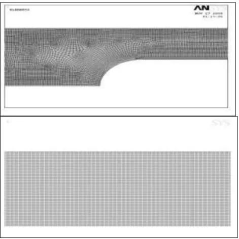
For short CNT the finite element analysis considers the two hemispherical end caps of CNT whereas the analytical result does not. The finite element mesh used in this analysis is shown in Figure 3. Two layers of elements are used through the thickness of the CNT.
Figure 3. Axisymmetric FEM models for the RVEs (TOP: short CNT, BOTTOM: long CNT at thickness 0.4 nm)
A stress contour plot of the first principal stresses in the RVE under the axial stretch is shown in Figure 4. It is seen that for short CNT the variation of effective Young’s modulus with matrix stiffness is same as that for long CNT. For specific matrix stiffness, the analytical result for short CNT is higher compared to the FEM result. The results for short CNT are shown in Table 2 and Figure 5. From the results, it can be realized that composite stiffness in case of short CNT can increase more than 3 times when the ratio
Emchanges from 1.5 to 5 GPa. The volume fraction
Figure 4. The first principal stresses under the axial stretch for short CNT (thickness 0.40 nm)
Table 2. Computed effective Young’s modulus of elasticity at varying Em for short CNT
Em (GPa)
σavg.
(GPa)
Ez, FEM
(GPa)
EzROM
(GPa) 1.5
2.5 3.5 5
0.0258 0.0428 0.0580 0.0815
2.5755 4.2775 5.7947 8.1450
2.7702 4.4147 5.9406 8.0609
Figure 5. Effect of matrix modulus (Em) on Young’s modulus (E z)
of composite for short CNT case
B. Effect of CNT thickness on effective Young’s modulus
The thickness of CNT is varied from 0.34 nm to 0.4
nm and thus the rois varied from 4.94 nm to 5 nm. The
Young’s modulus of the matrix used here is 5 GPa. It is seen that in case of both long and short CNT the effective Young’s modulus increases with CNT thickness. The results for long CNT are shown in Table 3 and Figure 6 and that for short CNT are shown in Table 3 and Figure 7. Composite stiffness can be increased by 1.16 times when CNT thickness changes from 0.34 nm to 0.40 nm in long CNT case. Composite stiffness in case of short CNT can be increased by 1.026 times when CNT thickness changes form 0.34 nm to 0.40 nm in short CNT.
Table 3. Computed effective Young’s modulus of elasticity at varying thickness of long CNT
CNT Thickness
(nm)
σavg.
(GPa)
Ez /Em,
FEM
Ez /Em,,
ROM
0.34 0.36 0.38 0.40
0.4812 0.5051 0.5310 0.5559
9.6240 10.1020 10.6210 11.1180
9.3182 9.7759 10.2336 10.6913
Figure 6. Effect of CNT thickness on Ez/Em, for long CNT case
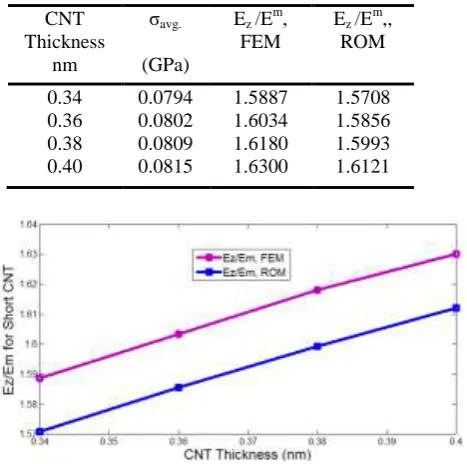
Table 4. Computed effective Young’s modulus of elasticity at varying thickens of short CNT
CNT Thickness
nm
σavg.
(GPa)
Ez /Em,
FEM
Ez /Em,,
ROM
0.34 0.36 0.38 0.40
0.0794 0.0802 0.0809 0.0815
1.5887 1.6034 1.6180 1.6300
1.5708 1.5856 1.5993 1.6121
Figure 7. Effect of CNT thickness on Ez/Em, for short CNT case
C.
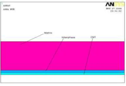
Effect of interphase volume fraction on effective Young’s modulusFigure 8. Partial view of FE area considering interphase (VF 2%) for long CNT
A material with stiffness 7 GPa and Poisson's ratio 0.30 considered as an interphase material. FEM results for both long and short CNT are enlisted in Table 5. The volume fraction of CNT is considered 0.0487 and CNT thickness is 0.4nm for both long and short CNT and the stiffness of the matrix is considered 5 GPa in this case.
Table 5. Computed effective Young’s modulus of elasticity considering interphase Volume Fraction of Interphase % . avg
, Long CNT GPa/
m zE E
,Long CNT, FEM . avg
, Short CNT GPa/
m zE E
,Short CNT, FEM 1 2 3 4 0.5561 0.5563 0.5565 0.5566 11.1220 11.1260 11.1300 11.1320 0.0813 0.0826 0.0831 0.0836 1.6260 1.6520 1.6620 1.6720
It is shown from the Table 5 that composite stiffness increases with increasing the volume fraction of interphase both in long and short CNT case. Compared to without interphase it is shown that composite stiffness increases up to 1.0012 times for long CNT and 1.026 times for short CNT when interphase volume fraction increases from 1% to 4%. Figure 9 shows the variation of effective Young’s modulus with interphase volume fraction for both long and short CNT.
Figure 9. Effect of interphase volume fraction on Ez/Em , for both Long and Short CNT case
V.
CONCLUSIONSThe material properties, Young’s modulus of the CNT-based composite is studied in this work by varying the matrix stiffness, CNT thickness and volume fraction of interphase. A 2-D axisymmetric model is used for the cylindrical RVE and this reduces computational work. It is observed that in case of both long and short CNT the effective Young’s modulus increases while the matrix stiffness varies from 1.5 GPa to 5 GPa. In both cases, the analytical estimates are very close to the FEM estimates that validate our results and claims. In this work, the CNT volume fraction for long CNT is kept 0.0487 and for short CNT it is kept 0.02147. It is also found that the effective Young’s modulus increases with CNT thickness for both long and short CNT and the analytical results are also very close to the FEM results. In all these cases the bonding between CNT and matrix is considered perfect. The effective Young’s modulus also increases as the interphase thickness increases from 1% to 4% by volume fraction.
REFERENCES
[1] S. Iijima,“Helical microtubules of graphite carbon,”Nature, vol. 32, pp. 56-58, 1991.
[2] M.S. Dresselhaus, G. Dresselhaus, and R. Saito, “Physics of carbon nanotubes. Carbon, vol. 33, pp. 883-891, 1995.
[3]M. Paradise and T. Goswami,“Carbon nanotubes-production and industrial applications,” Materials and design, vol. 28, pp. 1477- 1489, 2007.
[4] J. B. Bai and A. Allaoui, “Effect of length and the aggregate size of MWNTs on the improvement efficiency of the mechanical and electrical properties of nanocomposites – experimental investigation,” Composites Part A: Applied Science and
Manufacturing, vol. 34, pp. 689-694, 2003.
[5] E.W. Wong, P.E. Sheehan, and C.M. Lieber, (1997) “Nanobeam mechanics: elasticity, strength and toughness of nanorods and nanotubes,” Science, vol. 277, pp. 1971-1975, 1997. [6] Y.J. Liu and X.L. Chen,“Evaluations of the effective material properties of carbon nanotube-based composites using a nanoscale representative volume element. Mechanics of Materials, vol. 35, pp. 69-81, 2003.
[7] X.L. Chen and Y.J. Liu,“Square representative volume elements for evaluating the effective material properties of carbon nanotube-based composites,” Computational Materials Science, vol. 29, pp. 1-11, 2004.
[8] K. Lau, C.Gu, and D. Hui,“A critical review of nanotube/nanoclay related polymer composite materials,”
Composites Part B: Engineering, vol. 37, pp. 425-436, 2006.
[9] D. Qian, W.K. Liu, and R.S. Ruoff, “Mechanics of C60 in nanotubes,” Journal of Physical Chemistry, vol. 105, pp. 10753- 10758, 2001.
[10] D. Qian, G.J. Wagner, W.K. Liu, and M.F. Yu, (2002) “Mechanics of carbon nanotubes. Applied Mechanics Reviews, vol. 55, pp. 495–533, 2002.
[11] L.S. Schadler, S.C. Giannaris, and P.M. Ajayan, “Load transfer in carbon nanotube epoxy composites” Applied Physica
Letters, vol. 73, pp. 3842-3844, 1998.
[12] F.R. Jones, “Interphase formation and control in fiber composite materials,” Key Engineering Materials, vol. 116/117, pp. 41-60, 1996.
[13] S.A. Hayes, R. Lane, and F.R. Jones, “Fiber/matrix stress transfer through a discrete interphase. part 1: single-fiber model composite,” Composites Part A: Applied Science and
[14] N. Lopattananon, A.P. Kettle, D. Tripathi, A.J. Beck, F. Duval, R.M. France, R.D. Short, and F.R. Jones, (1999) “Interface molecular engineering of carbon fiber composites,” Composites
Part A: Applied Science and Manufacturing, vol. 30, pp. 49-57,
1999.
[15] R. Khare and S. Bose. “Carbon nanotube based composites- a review,” Journal of Minerals & Materials Characterization &
Engineering vol. 4, pp. 31-46, 2005.
[16] H. Qian, E.S. Greenhalgh, M.S.P. Shaffer, and A. Bismarck, “Carbon nanotube-based hierarchical composites : a review,”
Journal of Materials Chemistry vol. 20, pp. 4729-4956, 2010.
[17] W. Khan, R. Sharma, and P. Saini,“Carbon nanotube-based polymer composites: synthesis, properties and applications,”
Carbon Nanotubes - Current Progress of their Polymer