Effect of Stresses on the Walls of a Pressure
Vessel
D. C. Nnadi*1 C. C. Eze2, J.C Aririguzo3 and C. S. Agu4
Department of Mechanical Engineering, Michael Okpara University of Agriculture, Umudike, Nigeria
ABSTRACT
The effect of stresses on the walls of a pressure vessel was investigated. The pressure vessels are used in power generation industry for fossil and nuclear power, the petrochemical for storing and processing crude oil as well as gasoline. The research sought to increase the safety standard of the manufacturing and use of pressure vessels. Results obtained showed that the best working pressurenofn the vessel was at 9.90N/m and thicknessof 90mm.
1.0INTRODUCTION
In the Chemical, Oil and Gas Industries, fluids are transported or stored at very high pressure to meet several requirements of the company, consequently there is a need for safe storage and transportation of these fluids from one place to another [1].Among the instruments used to achieve a safe storage and transportation of these fluids (e.g. petroleum products, gases etc.) is the pressure vessel.A pressure vessel is a container designed to carry, store or receive fluids (gases or liquids) at a pressure substantially different from the ambient pressure [2]. In addition to the oil and Gas industry there are simple pressure vessels found around us such ones as gas cylinders, compressors,steam boilers and car tyres.The internal pressure is usually higher than the external pressureexerted on the walls of containing vessel. The fluid inside the vessel usually undergochanges in states as in the case of steam boilers or may combine with other reagent as in the case of chemical reactor.Fluid pressure vessels often has a combination of high pressure together with high temperature, therefore in some cases flammable fluids or highly radioactive material are produced. The pressure differential is usually dangerous, and fatal accidents have occurred in the history of pressure vessel development and operation [3].
Pressure vessel are used in a number of industries, for example, the power generation industry for fossil and nuclear power, the petrochemical industry for storing and processing crude oil as well as storing gasoline in service station, and the chemical industry [4]. It is in this class of equipment that the reaction, separation and storage of raw material occur. Similarly, pressurized
equipment is required for a wide range of industrial plant for storage and manufacturing purpose.
Pressure vessel aremade of cast iron, carbon steel, stainless steel and nonferrous alloys, they are of different shapes;spherical and cylindrical [7]. The cylindrical vessels are generally preferred due to their simplicity some examples of cylindrically shaped type include; boilers, heat exchanger and chemical reactors. Spherical vessels have an advantage also as it requires thinner walls for a given pressure and diameter than the equivalent cylinder. Therefore, they are used for large gas or liquid containers, containment buildings for nuclear plant and so on.
. Pressure Vessels are classified:(i) according to their dimensions (thick and thin shells); a pressure vessel is referred to as thin shell when the wall thickness (t) is less thand/20 of itsdiameter (d) and thick shell when the wall thickness (t)is greater than or equal to d/20 of its internal diameter (d) [5]. And(ii) According to end construction (open and closed end); a pressure vessel is referred to as open end when one of its end is not closed e.g. a simple cylinder with a piston. And closed end when the two ends are closed with dome or dish e.g. tanks.[8]
Safety is the primary consideration in pressure vessels, especially for nuclear reactor vessels, due the potential impact of a possible accident. In general however, the design is a compromise between consideration of economics and safety. Therefore the possible risks of a given failure and its consequent are balanced against the effort required for its prevention; the resulting design should achieve an adequate standard of safety at minimum cost.
and types of failures involved in pressure vessels and the categories and types of stresses and loadings for a specific vessel.
These therefore necessitates the study of the effects of stresses on pressure vessels, studies on the causes of failures of pressure vessel when it is pressurised, analysis on the safety parameters for allowable working pressure of the pressure vessel which complies to ASME VIII standard and the determination of the stress exacted on the walls of the pressure vessel at various diameters.
The objective of this research work is to increase the safety standard in manufacturing and use of pressure vessels thereby reducing causes of hazards in the workshop and improve the adherence/compliance of staff to safety measures by getting them enlightened of the effects of unsafe condition and unsafe action they take.and to reduce the trend of shattering of vessels when subjected to high pressure as a result of non-compliances to the manufactures specification or the effects of internal
pressure/temperature.
2.0 MATERIALS AND METHOD
Symbols Used;
σ
L = Longitudinal stress (axial)
σ
r = Radial stress
σ
c = Hoop or Circumferential stress
P = Pressure (Internal)
R = Radius (Outer) of the vessel
r = Radius (inner) of the vessel
δt = change in thickness
δd = change in diameter
ec = Circumferential strain
E = Young‟s Modulus
1/m = Poisson Ratio
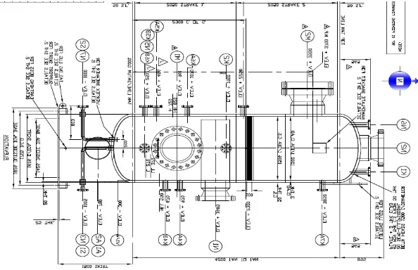
Shown below is a model pressure vessel fabricated and used for our analysis. It is an intellectual property of Energy Works LTD known as soku pressure vessel
Figure 3.1An autographic diagramof a designed pressure vessel
The material used for fabrication of the pressure vessel and consequently used as the criteria for the analysis include: stainless steel plate of 90mm thickness, flanges, nozzlesbolts and nuts. These are also the factors that affect the strength and reliability of the vessel
2.1 Stresses in Pressure Vessel
The hydrostatic pressure causes stresses in three dimensions and they are normal stresses.
Longitudinal stress (axial) σ
L
Radial stress σ
r
Hoop stress σ
Figure 2.2; Stresses exacted on the walls of a Pressure Vessel
Longitudinal Stress
Considering that the pipe ends are closed and pipe is subjected to an internal pressure „P1‟ (because it
is exposed to atmospheric pressure that is external
pressure (P
2) is zero) alone the pipe may fail as
shown in the figure below.
Figure 2.3; Longitudinal Stress
Elements resisting this type of failure would be subjected to stress, and the direction of this stress is parallel to the longitudinal direction of the pipe. Hence this stress is called longitudinal or axial stress and is usually less than the hoop stress (Engineers edge 2000)
The longitudinal stress (σ
L) can be calculated as
follows for thick shell wall (thickness is greater or equal to d/t);
σ
L =
Force acting on the end cover due to internal pressure Area of cross -section of the cylinder
σ
L = [
Pr2
𝐑𝟐−𝐫𝟐] (1)
Radial Stress
Radial stress is a stress in directions coplanar with bothperpendicular to the symmetry axis.
The radial stress for a thick-walled pipe is equal and opposite to the gauge pressure on the inside surface, and zero on the outside surface.
The radial stress is always compressive.
Figure 2.4; Radial Stresses in a Pressure Vessel
Each element of the pipe is subjected to radial stress which acts in radial direction and calculated as
σ
r = [
Pr2
𝐑𝟐−𝐫𝟐][
R2
𝐫𝟐+ 𝟏] (2)
[ 5 ] Hoop Stress
Hoop stress in a pressure vesseltends to split the vessel into two halves. The failure of the vessel in
two halves in fact is possible across any plane of axis and to the radius of the vessel.
Figure 2.5; Hoop Stress in a Pressure Vessel
Elements resisting this type of failure would be subjected to stress and direction of this stress is in both directions on every particle in the cylinder wall [6]. Hence the above stress is called Circumferential or Hoop Stress and can be calculated as
σ
c = [
Pr2
𝐑𝟐−𝐫𝟐][
R2
𝐫𝟐− 𝟏] (3)
Maximum Share Stress, Change in Diameter and Change in Thickness;
Maximum Share Stress τ
MAX= [
𝛔𝐜−(−𝛔𝐫) 𝟐 ] (4)
Change in Diameter δd= ec × d (5)
Whereec= =
1
𝐸[σc +
1
𝑚(σr − σL)] (6)
Change in Thickness δt = D ×es (7)
Where
ec=
1
𝐸[σc +
1
𝑚(σr − σL)] (8)
Determination of Stresses
In studying the stresses exerted on a thick shell pressure vessel as a result of the pressure, the change in the diameter of the Vessel as a result of pressure exerted in the inside diameter, a typical problem of a vessel made of stainless steel is used to evaluate the stresses induced by the pressure on the walls of the vessel designed for storing
Hydrocarbon/liquids/water which have the
following data. Shell thickness t
90𝑚𝑚
Internal Pressure P
9.9N/𝑚𝑚2 Tangent Length L
6,595 𝑚𝑚
Young‟s Modulus
20Gpa Poisson Ratio
0.29
Calculation of Longitudinal/Axial Stress(σ
L)
It is observed that as pressure expands the internal diameter takes a minute increase of about 0.50mm relative to the wall thickness.Since the cylinder has closed ends, to calculate the tensile longitudinal stress (assumed constant over the cross section) we apply equation (1) and assume 12 diameters with initial diameter of 1426mm.
σ
L = [
Pr2
R2−r2]
When t = 90mm, d
1 = 1426mm, r1 = 713
From d = D - 2t hence D = d + 2t D
1 = 1606mm
and R
1 = 803mm
σ
L1 =
9.900 × (713)2
(803)2−(713)2 =
36.8869N/mm2
Calculation of Radial Stress(σ
r)
σ
r = [
Pr2 R2−r2][
R2 r2− 1]
1 1
From d = D - 2t hence D = d + 2t D
1 = 1606mm
and R
1 = 803mm
σ
r1 = [
9.900 × (713)2
(803)2−(713)2] [ (803)2 (713)2− 1]
σ
r1 = 9.90045N/ mm 2
Calculation of Hoop/Circumferential Stress(σ
c)
σ
c = [
Pr2
𝐑𝟐−𝐫𝟐][
R2
𝐫𝟐+ 𝟏]
When t = 90mm, d
1 = 1426mm, r1 = 713
From d = D - 2t hence D = d + 2t D
1 = 1606mm
and R
1 = 803mm
σ
c1 = [
9.900 × (713)2
(803)2−(713)2] [ (803)2 (713)2+ 1]
σ
c1 = 83.6739N/ mm 2
Calculation for Maximum Shear Stress(τ
MAX)
τ
max= [
𝛔𝐜−(−𝛔𝐫) 𝟐 ]
At d1= 1426mm, σc1 = 83.6742N/mm and σr
1 =
9.90045N/mm
[83.6739−(−9.90045 )2 ] = 46.7872N/ mm2
Determining the Increase in the Internal Diameter(δd)
ec = =
1
𝐸[σc +
1
𝑚(σr − σL)]
At d1= 1426mm and σc1 = 83.6742, σr1 =
9.90045, σL1 = 36.8869 and 𝑚1= 0.29
ec1 = =
1
20𝑥109[83.6739 + 0.29 (9.90045 −
36.8869)] ec1= 3.7924 𝑥109
δd1 = 3.7924 𝑥109 × 1426
δd1 = 5407.9716 𝑥109
3.3.6 Determining Change in the Wall Thickness(δt)
es = =
𝟏
𝑬[𝛔𝐜 −
𝟏
𝒎(𝛔𝐫 + 𝛔𝐋)] hence, δt = D
×es
At d1 = 1606mm and σc1 = 83.6739, σr1 =
9.90045, σL1 = 36.8869 and 𝑚1= 0.29
es1 = =
1
20𝑥109[83.6742 − 0.29 (9.90045 +
36.8869)]
es1= 3.5053 𝑥109
δt1 = 3.5053𝑥109 × 1606
3.0 RESULTS AND DISCUSSION
Table 1 the ratio of thickness to diameter and the stresses
N D d t t/d P σ
L σr σc τmax δd δt
1 1426 1426 90 0.0631 9.90 36.8869 9.9005 83.6739 46.7872 5407.95 5629.80
2 1450 1450 90 0.0621 9.90 37.5446 9.9005 84.9893 47.4449 5580.51 5805.26
3 1500 1500 90 0.0600 9.90 38.9151 9.9000 87.7302 48.8151 5948.69 6180.20
4 1550 1550 90 0.0581 9.90 41.2517 9.9000 92.6408 51.2695 6475.03 6730.29
5 1600 1600 90 0.0561 9.90 41.6568 9.9018 93.2136 51.5577 6720.37 6965.28
6 1650 1650 90 0.0545 9.90 43.0280 9.9007 95.9560 52.9284 7123.80 7375.51
7 1700 1700 90 0.0529 9.90 44.3914 9.9011 99.0144 54.4577 7566.04 7828.12
8 1750 1750 90 0.0514 9.90 45.7711 9.9003 101.4421 55.6712 7965.96 8231.24
9 1800 1800 90 0.0500 9.90 47.1429 9.9000 104.1857 57.0429 8404.68 8676.68
10 1850 1850 90 0.0486 9.90 48.5148 9.9000 106.6573 58.2787 8829.96 9106.28
11 1900 1900 90 0.0474 9.90 49.8869 9.8976 109.6739 59.7857 9317.31 9602.24
Typically, the range of Stress, change in diameter and change in thicknesses at constant Pressure result for different diameters as shown in tables (1, 2, 3, 4, and 5). From the result of the study, a graph of stresses, change in diameter and change in thickness against diameter for different ranges.
Effect of Longitudinal Stress on the Vessels Diameter
Fig.1 Graph of longitudinal stress and diameter The graph above, (showing the values of the longitudinal stress at various diameter of pressure vessel) the longitudinal stress in the vessel increases as the diameter increases at a constant pressure and thickness. This increase the longitudinal stress will make the vessel to fail easily at a slightest increase in temperature.
As the pressure vessel is pressurised, the pressure increases the diameter of the vessel, this in turn reduces the thickness of the vessel. It is therefore better to reduce the diameter instead of increasing it that is the vessel should be fabricated with a lower internal diameter.
Effect of Radial Stress on the Vessel’s Diameter
The radial stress exacted on a thick shell pressure vessel is equal to the pressure applied As shown in the table above, the radial stress at any point on the vessel for different diameters of the metal of 90mm thick wall is approximately equal to the pressure applied on the vessel.
Effect of Hoop Stress on the Vessel’s Diameter
Fig 2 Graph of Internal diameter and the hoop
stress exacted in a vessel of 90mm thickness
As shown in graph 4.2 above, the hoop or circumferential stress increases as the diameter of pressure vessel is equally increased at constant pressure (9.90N/mm2) and thickness (90mm) this increase in the hoop stress will make the vessel to fail at its circumference.
Failure of vessel falls as a result of hoop stress usually have more devastating effects than longitudinal and radial stress as hoop stress is alwaystwice of the longitudinal stress that is greater than the radial stress.
This equally reviles that more consideration and care should be taken to keep the hoop stress at its minimum when designing a pressure vessel
Effect Maximum Share Stress the Vessel’s
Diameter
Fig. 3 Maximum share stress and diameter
As shown in graph 4.2 above, the Maximum share stress varies directly as the diameter of pressure vessel at constant pressure of (9.90N/mm2) and thickness (90mm). The share stress is the average of hoop stress exacted in the vessel and the radial stress.
This implies that the maximum forces tending to produce share of the vessel increases as the diameter increases. Since the thickness of the vessel is constant (no increase or decrease) and the
specification), it is therefore necessary to keep the diameter as low as possible best in order to the reduce the share stress at any point in the vessel for any thickness and diameter.
This equally reviles that more consideration and care should be taken to keep the hoop stress at its minimum when designing a pressure vessel
Effect Change in Thickness on the Vessel’s
Diameter
Fig 4 Graph of change in thickness and diameter
As the pressure vessel is pressurised, the pressure increases the diameter of the vessel, this in turn reduces the thickness of the vessel. That is at a constant pressure, increase in the diameter reduces the thickness. This thereby makes the vessel‟s material to be brittle and can burst at any slight increase in temperature. It is therefore necessary to increase the thickness as the diameter is increased vice vasa.
The Ratio of Thickness to Diameter and Maximum Shear Stress
Fig.5 Graph of maximum share stress and the ratio of thickness to internal diameter
Graph 4.5 shows that as the maximum share stress increases the ratio of share stress to diameter decreases at constant pressure. Thus as the share stress increases, the safety of the pressure vessel cannot be guaranteed as tends to make the vessel to fail.
4.0 Conclusion and Recommendation
4.1 Conclusion
This study has been able to verify the effect of stresses in the walls of a cylindrical thick shell Pressure vessel, the causes of vessel failure, and possible means of reducing the causes of vessel failures. The method of determination of stresses is based on Lame‟s equation for a vessel subjected to internal pressure only.
This study reviles that increases in the diameter at a constant thickness and pressure increases the stresses (longitudinal, radial and hoop), the maximum shear stress increases with increase in diameter while the ratio of thickness to the diameter decreases as the maximum shear stress increases Thus reduces the safety and reliability of the pressure vessel. It is therefore necessary to keep the diameter at the possible minima.
Due to the hazards associated with Pressure Vessels which is as a result of combination of high pressure with high temperature especially cases of flammable fluids or highly radioactive materials are produced.
It is Imperative that accurate inspection and check-up must be carried on the pressure vessel by QAQC and NDT qualified personnel‟s before and vessel can be satisfied ready for use.
Some of the activities carried out by Quality personnel include
Dimension check up
Ensure compliance with standard code
Ensure that welding procedure specified in the WPS are followed strictly.
Ensure that tolerance, fit up and alignments are in accordance with the approved design standards Non-destructive evaluation covers a wide group of analysis techniques used to evaluate the properties of pressure vessel material/weld without damage of the pressure vessel‟s part.
Some NDT methods include: Hydro test
Radiographic test: this the use of radioactive Isotope (x-rays or gamma rays) to examine the efficient and reliability of welded joint.
Magnetic particle inspection: this is the application of iron filings in welded joint, this adhere to any break in the welded joint. It is used to detect too small to be seen with ordinary eye.
Ultrasonic inspection: this method is used in the examination of groove weld defect which are inside the welded points. The transducer sends the ultrasound through the welded joint and the inner wall of a defect surface will send the wave bouncing back. It can also be used to measure thickness of weld, detect corrosion slag inclusion and uneven penetration.
Pneumatic test: involve the use of air produced from compressor and soap solution to determine the pressure capacity of a pressure vessel. This often detect leakages the welded point.
Other processes in this certification stage include Blasting: This involve the use of Grit and high pressure produced by the compressor to remove rust from the inside and outside surfaces of the pressure vessel.
Piping and Instrumentation: this is the assembling and connections of pipes and instrument use to convey fluids for various purposes. There are different styles of pipe connections but each style is adopted for a particular pressure vessel based on the specification in the P&ID diagram which is done with consideration of the use
4.2 RECOMMENDATION
From this work, increase in diameter has implication on the stresses exacted on a cylindrical thick shell pressure vessel. Based on the result, I recommend that in order to minimise the stresses (longitudinal, radial and hoop) at any thickness, the diameter should be minimised;
During material consideration stage, selection of a large diameter should in turn be followed by a high wall thickness. The circumferential stress should be kept at
a possible minimum by reducing the diameter of the vessel.
ASME code should be used during
fabrication of a pressure vessel while BIVP codes/standard should be used during maintenance of a pressure vessel.
Each fabricated pressure vessel should have its specification (such as design pressure, operating temperature, maintenance/check-up list and so on)tagged to it.
References
[1] Affendi b. Hussin‟2000, Design, Analysis and Fabrication
of Pressure Vessel, Department ofManufacturing
Engineering March 2008, University Technical Malaysia Melaka
[2] Bernsen S.A., F.A. Simonen and K.R. Balkey (2006). PRA and Risk-Informed Analysis, Chapter 45 Companion Guide to the ASME Boiler and Pressure Vessel Codes – Second Edition – Volume 3, ASME Press, New York, USA.
ORNL/TM-2004/245, October 2004.
[4] Dillstrom P. (2003). A Short Description of ProSACC, NURBIM Report D4/Appendix G, DNV, Stockholm. [A probabilistic fracture mechanics code for pressure vessels and piping that was developed in Sweden for commercial power plant applications].
[5] Rajput,R.K. (2012), Strength of Materials (Mechanics of Solids), S. Chand and Company
Machine Design.S Chand Publishers, New Delhi. [7] Megyesy, Eugene F. "Pressure Vessel Handbook, 14th
Edition." PV Publishing, Inc. Oklahoma.City, OK [8] G. C. Dioke,A. Offiong and D.C. Nnadi .Design of a
single phase 3-level, 4-level, 5-level Inverter-Fed
Asynchronous Motor-drive with Diode- clamped