Some Improvements on Active Queue Management
Mechanism Based on Adaptive Fuzzy Control
Nguyen Kim Quoc1,*, Vo Thanh Tu2 and Nguyen Thuc Hai3
1 2 3
College of Sciences, Hue University, Vietnam College of Sciences, Hue University, Vietnam
Ha Noi University of Science and Technology, Vietnam
Abstract
Active queue management operates at network nodes to control the number of packets in the queue of nodes, by actively receiving packets when the queue is not full, removing packets when the queue is full or notifying bottlenecks even in the embryonic period of the bottlenecks due to to-be-full queue. In recent years, scientists have used fuzzy logic to improve queue management mec hanisms. Overall, these improvements have used Mamdani fuzzy system with a fixed structure with triangular functions for input and output variables, so they do not adapt to the changing state of the network. We propose a adaptive fuzzy control (AFC) model to improve the effectiveness of active queue management mechanisms.
Keywor ds: Congestion Control, Active Queue Management, Fuzzy Logic
Received on 20 April 2015, accepted on 21 April 2015, published on 05 November 2015
Copyright © 2015 N.K. Quoc et al., licensed to EAI. This is an open access article distributed under the terms of the Creative Commons Attribution licence (http://creativecommons.org/licenses/by/3.0/), which permits unlimited use, distribution and reproduction in any medium so long as the original work is properly cited.
doi: 10.4108/eai.5-11-2015.150607
1. Introduction
By analyzing AQM mechanisms using fuzzy logic, these improvement projects of AQM mechanisms based on queue length and speed of incoming traffic, surrounding the modification of RED and REM. In these mechanisms, FEM [6] and FUZREM [31] are the two mechanisms presented in details, clearly and offering the best results. Therefore, we will analyze and assess these two mechanisms to clarify the operations of AQM mechanisms using fuzzy logic. Generally, these mechanisms apply fuzzy control using Mamdani fuzzy system of triangular functions, owning deductive fixed lawful system, input variables are the difference between the instantaneous queue length with referential queue length, taken on two consecutive times and output variables are the probability of packet marking. This makes control mechanisms rough and the adaptability low. Thus, we propose solutions to build adaptive fuzzy controller (temporarily called AFC) combined with present active queue management mechanisms to improve the performance of the active queue management mechanisms [3][4][14][18][21].
*Corresponding author. Email: [email protected]
So, the opening of the paper presents the mathematic base of fuzzy logic, next is a survey to assess the active queue management mechanisms using existing fuzzy logic. Since then, we propose the adaptive fuzzy control model to improve the active queue management mechanism in order to overcome some limitations in existing mechanisms. Based on the theoretical model, we deploy to install simulation, develop FLREM and FLRED innovative mechanisms. In particular, the FLRED mechanism improves the RED mechanism based on the queue length, the FLREM mechanism improves the REM mechanism based on the combination of the queue length with the speed of incoming traffic. The next of the paper is the evaluation on simulation of mechanisms proposed compared to traditional mechanisms and mechanisms using fuzzy control. The simulation results of AQM mechanisms show the performance of traditional mechanisms increased when applying fuzzy control, and this factor is enhanced when using the adaptive fuzzy controller - AFC for mechanisms .
2. Related Works
2.1.
Operation of RED mechanism
congestion, RED is one of the mechanisms used to control the congestion at the network node by checking the average length when the packet queue and make a decision to mark or discard the packet to the probability increases as the average length of the queue exceeds a set threshold.
When packets arrive at network nodes, RED active queue management mechanism calculate the average queue length by the formula: 𝑘̂ = (1 − 𝜔) ∗ 𝑘̂ + 𝜔 ∗ 𝑘, with is weighted queue to control the volatility of average size (0
1) and k is the current queue length
Then RED compare the average queue length with two thresholds minimum minth and maximum maxth. If the
average queue length is less than minth do not have any
packages marked (or probability marked by 0). When the average queue length greater than maxth, all incoming
packets are marked (or probability marked by 1) and in fact this package is removed. When the average queue length is between minth and maxth each incoming packet is marked
with a probability 𝑝𝑎 ∈ [0, 𝑚𝑎𝑥𝑝], is defined by the formula (1) and (2) follows:
ˆ
th
b p
th th
k min p max
max min
(1)
1 *
b a
b
p p
count p
(2)
2.2.
Operation of REM mechanism
The first idea of REM is stable input rate and link capacity of the queue, regardless of the number of users sharing links [1][11][15][19][23]. Each output queue of router installed REM mechanism and maintains a variable called 'price'. Price as a factor in evaluating congestion. Price is updated periodically or asynchronously, based on the asymmetry of the asymmetric load and the asymmetry queue size. The load is unworthy of the difference between the speed of the flow of data into and existing capacity of the link. Unworthiness of the queue size is the difference between the required target queue size with queue size of the router.
This price increase if the total weight of unworthiness is positive, and decreases in the opposite case. Total weight is positive when one input exceeds the binding capacity or there are too many packages in the queue backlog should be cleared, and negative in the opposite case. As the number of users increases, the load is not uniform among the queue size increases, boosting the price and therefore the probability of congestion marked. This will send a stronger signal congestion to the source, then the source of reduced growth. When downloading the source is too small, will not sync negative, and marked probability reduce and enhance the of load power. Until unworthiness is towards to zero, hig h efficiency and negligible decrease, so the delay in equilibrium. The queue is deleted in equilibrium if the queue set to 0.
REM clear control through updates its price, this is the first character of REM. Exactly, queue size l, price pl(t) in
stages t is updated by the formula following [1][20]:
*
( 1) ( ) ( ( ( ) ) ( ) ( ))
l l l l l l l
p t p t b t b x t c t (3)
Where, >0 and l>0 constants are small and
[z]+=max{z,0}. Here, bl(t) the average queue size of the
queue l in time t and *
0
t
b the target queue length, x(t)
average download speeds of queue l at the time of t, and cl(t)
allowed bandwidth of queue l at the time of t. The difference in load is xl(t)-cl(t) and the queue size bl(t)-bl*. The constant
l can be set up by each individual queue an d are updated
according to the performance and latency in each queue. The constant REM control response changes depending on network conditions. Parameters price will increase if the speed deviation of the load and queue size is positive and the price will decrease in the opposite case. At equilibrium, stability and p is calculated using the formula:
*
( ( ) ) ( ) ( ) 0
l b tl bl x tl c tl
(4)
This can be kept when loading the input speed equal to the speed of processing in routers (xl=cl) and the number of
packets in the queue with the desired queue size bl bl* REM's second idea is to use a total of price links along the path of the packet, this total reflects signs of congestion on the path, the total price to be embedded into the terminal to mark probability. Forms exponentially increase the probability of marking is very important in a large network. At last, the probability of marking a packet passes through multiple congested link from source to destination depends on the probabilities associated marks at all links in the path. When and only when the associated component marking probability is exponential in its price link. This led to the arrival terminal will be marked probability increases exponentially with the total price of all links in congested link in its path. This total is a true measure of congestion in the path of the packets. Since it is embedded in the terminal to mark probability, it can be easily estimated from the sources of its own packets are marked, and is used to design adaptation loads of it.
Suppose that a packet passes through the links l=1,2, …,
L have price pl(t) at time t, the marking probability ml(t)
queue l at time t is:
( )
( ) 1
p tl lm t
(5)Where, >1 is constant and marking probability at the end of the packet is [18][19][22]:
( )1
1 1 ( ) 1
l l
L p t
l l
m t
(6)Probability high marks when large sum∑ 𝑝𝑙 𝑙(𝑡). When the
marking probability at the link ml(t) small, should pl(t) small.
So, the probability is marked at the end by the above formula is proportional to the sum of the pl(t) along the way and
mark probability at end approximately:
loge
l( )l
p t
3. Fuzzy controller
3.1.
Mathematical representation of the fuzzy
approximation
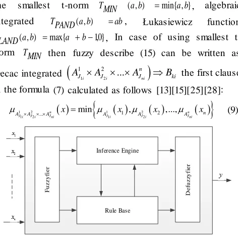
At the MISO fuzzy systems are nonlinear mapping from
input vectors x
x1,..., xn
Tn to output y(Figure1). In the theory of fuzzy sets and fuzzy logic ([4], [8]), allows dimming chemical inputs using fuzzy operators chemical transfer function data clearly the basis of fuzzy sets and fuzzy rules with the assumption including: p fuzzy rules are represented as a set of fuzzy descriptive (fuzzy Implications) after [4][7][8][12][24][25]:
1 2
1 2
: ...
i i ni
n
i AJ AJ AJ Bki
(7)
with i=1..p, notation AB or just fuzzy describe for conditions statements If A Then B and i
j
A , Bk is the fuzzy set is defined as follows :
,
i: x
j
i
j i A i i
A
x
x
,
:
k
k B
B
y
y
y
(8)
with i
,
[0,1]
kj B
A
respectively, the membershipfunctions of j and k inputs xi and output y.
The basic problem of fuzzy systems in fuzzy inference mechanism (fuzzy inference) and defuzzification methods (defuzzification) used to calculate the output of fuzzy system clearly specify when the input given on the basis of fuzzy rules have known. This fuzzy inference mechanism is built on the success of inference rules. To calculate the the first clause in the formula (7) we can use any t-norm does [30] as the smallest t-norm TMIN (a,b) min{a,b}, algebraic
integrated TPAND(a,b) ab, Łukasiewicz function
TLAND(a,b) max{a b1,0}, In case of using smallest t-norm TMIN then fuzzy describe (15) can be written as
Decac integrated
1 2
1 2
...
i i ni
n
J J J ki
A A A B the first clause in the formula (7) calculated as follows [13][15][25][28]:
1 2 1 2
1 2 ... 1 1 2 2
min , ,...,
n n
Ji Ji Jni Ji Ji Jni n
A A A x A x A x A x
(9)
F u z z y fi e r Inference Engine D e fu z zy fi e r Rule Base
Figure 1: MISO fuzzy control system
To calculate the fuzzy description of each rule or the
output of each rule can be used to describe the fuzzy operator (t-norm or t-conorm). Some fuzzy operator describe common include: Zadeh x y max{1x, min{x, y}}, Lukasiewicz x y min{1, 1xy}, Mamdani x y
min{x, y} và Larsen x y xy. Where the operator using fuzzy Mamdani describes the output of the ith rule (Ri),
denoted as
,
,
: , y
i
n
i C
C y x y x calculated as
follows:
1 2 1 2 1 2 1 2 ... ...,
,
min
,
ni J J J
i i ni n
ki Ji J i Jni
C A A A
B
A A A
x y
x y
x
y
(10)Finally, to calculate the output of fuzzy system can be used as a defuzzification method of defuzzification focal point COG (Center Of Gravity) after:
1 1 ( , ) ( , ) ( , ) i i p i C i z p C i z
C x z dz y F x
x z dz
(11)with ci is the center of
Bki
y
for to ithrule. Normallywe choose
ki B
y
symmetry across a vertical axis throughthe peak to ci is the midpoint of
Bki
y
The equation (19) is a model of Mamdani fuzzy system with COG defuzzification method and is used as the fuzzy
approximation F(x,θ) with 1,..., c T p c
.
3.2.
Fuzzy logic controller
Fuzzy logic controllers, like expert systems, can be used to model human experiences and human decision making behaviors. In FLC the input-output relationship is expressed by using a set of linguistic rules or relational expressions. The FLC basically consists of four important parts including a fuzzifier, a defuzzifier, an inference engine and a rule base. As in many fuzzy control applications, the input data are usually crisp, so a fuzzification is necessary to convert the input crisp data into a suitable set of linguistic value that is needed in inference engine. Singleton fuzzifier is the general fuzzification method used to map the crisp input to a singleton fuzzy set. In the rule base of a FLC, a set of fuzzy control rules, which characterize the dynamic behavior of system, are defined. The inference engine is used to form inferences and draw conclusions from the fuzzy control rules. Figure 1 shows the fuzzy logic controller architecture. The output of inference engine is sent to defuzzification unit. Defuzzification is a mapping from a space of fuzzy control actions into a space of crisp control actions [15][19][25].
1) Layer of Inputs : language input variable is the variable that represents the main factors affecting the operation mechanism of REM.
the input values to set the corresponding language.
3) Layer of Rules : this layer contains the basis for inference rules. Code base is a set of fuzzy rules of the form IF-THEN, for n variables in x1,..,xn, the y variable, fuzzy
rules of the form R: IF (x1 is A1).. (xi is Ai) … (xn is
An) THEN y is B. Where 𝐴𝑖 and B are fuzzy sets of linguistic variables x1, x2, .., xn and the outcome variable y.
4) Layer of Inference Engine: this layer performs the function of the total results of the nodes in the rule layer to send, through the permit OR (Max).
5) Layer of Defuzzifier: functional class implements defuzzification to obtain results, the results are calculated probability of packet marking optimization under the current state of the network. The output f(x) of this fuzzy controller with singleton fuzzifier, inference engine and center-average defuzzifier can be calculated as:
𝑓(𝑥) =
∑𝑘𝑗 =1𝑦0𝑗. ∏𝑛𝑖=1𝜇𝑗𝑖(𝑥𝑖)
∑𝑘𝑗=1∏𝑛𝑖=1𝜇𝑗𝑖(𝑥𝑖)
(12)
Where y0 is the center value of the output fuzzy set b,
𝜇 (𝑥) is the membership function for fuzzy sets. In our proposed model we use two input variables to fuzzy controller which present the congestion measures for the packet loss, queue length and the output will be the drop probability value.
3.3.
Mamdani fuzzy system
Mamdani fuzzy controller (also known as estimates Control) used control method of Mamdani is first fuzzy control method. It is used in cases where the condition clause and the clause conclusions are fuzzy values, the following general form [4][7][9]:
𝑅𝑖: 𝐼𝐹 (𝑥1 is A1 𝑗
) ∧ … ∧ (𝑥𝑚 is A𝑚
𝑗
) 𝑇𝐻𝐸𝑁 (𝑦1 is 𝐵1 𝑗
), … , (𝑦𝑛 is 𝐵𝑛 𝑗
) (13)
Where m is the number of the input signal, n is the number of output signal, j = 1... k, where k is the number of control rules. Conclusion of Mamdani fuzzy control methods are fuzzy clauses.
3.4.
Sugeno fuzzy system
Sugeno fuzzy model published by Takagi, Sugeno, Kang desire to develop a systematic approach to establish the fuzzy rules from the data set into place. Basic fuzzy Sugeno model has the form [4][7][9]::
𝐼𝐹 (𝑥1 𝑖𝑠 𝐴1 𝑗
) 𝐴𝑁𝐷 … 𝐴𝑁𝐷 (𝑥𝑛 𝑖𝑠 𝐴𝑛 𝑗
)
𝑇𝐻𝐸𝑁 𝑦 = 𝑓𝑗 = 𝑝0 𝑗
+ ∑ 𝑝𝑖𝑗𝑥𝑖 𝑛 𝑖=1
(14)
With 𝐴𝑖 the fuzzy conditions and 𝑦 = 𝑓𝑗is clearly a function of the conclusions. Usually 𝑓𝑗 polynomial of the input variables 𝑥𝑖 or any function as long as the appropriate describe the output of the fuzzy system in the domain defined by the premise of the rule.
3.5.
Problems exist AQM using fuzzy logic
In general, the mechanism of fuzzy control applications
using Mamdani fuzzy system with the function of triangular shape, with the input variable is the difference between the instantaneous queue length with reference queue length, taken on two consecutive time and the output variable is the probability of packet marking. However, these mechanisms also exist a number of the following:
First, the use of triangular membership functions to calculate simple, but it makes the controller is not smooth [36]. To overcome this drawback, we offer solutions in the form of a bell-shaped function used to represent values of fuzzy variables in the input and output of the fuzzy controller.
Second, the value of the variable probability of marking packets at the output of the fuzzy controller is shown the qualitative factors of the people participating in the control system, this value has to be some standard mechanism of the interval [0, 1]. However, in the FEM, the coefficients are adjusted by hand, there should be self-correcting mechanism in the output coefficient for adjusting the value of the packet marking probability of the system quantitatively, to be valid interest in accordance with the status of the network.
Third, the reference queue length (qref) used in themechanism is set fixed value, usually the threshold is 80% of the capacity of the system (such as buffer size). However, there are strategies to build a model to change the reference value in accordance with the state of the network. For example, when the road is clear, then set the value to low-latency queue in small, whereas the high reference value set to limit the loss.
Fourth, the parameters of the fuzzy controller (number of functions, the value of the function, the number of laws, rules weights) were fixed since the design, should not be changed to suit the situation network.
Thursday, the major cause for the AQM mechanism using fuzzy controller performance is not high due to this mechanism using Mamdani fuzzy system for their fuzzy controller. According to the researchers in the field of automatic control, the Mamdani fuzzy system does not work effectively with Sugeno fuzzy systems, especially in the control system such MISO [7] [10].To overcome this limitation of the mechanism, we propose to model AFC using fuzzy Sugeno with a bell-shaped function of the adjustment mechanism and target values self-control mechanism control output probabilities. AFC fuzzy controller built into the rest of the article.
4. Proposed adaptive fuzzy controller
4.1.
Building adaptive fuzzy controller
Figure 2. Improved model AQM mechanism by AFC
The AFC model is described as follows:
Based on the input state that Gm determine referenceoutput ym (queue length, bandwidth or a combination of both
factors) for the network. The value is set ym depending
resource capacity of the system and the status of the network and is set 𝑦𝑚 = 𝛼𝑦𝑚𝑎𝑥.
Closed-loop control system, the input value e(t), e(t-T)is the deviation of output y compared with the reference value ym will be standardized by K1 and K2 the previous
coefficients going into the fuzzy controller.
After the input data in a standardized, data will be sent to the fuzzy controller. Here, fuzzy control system components: fuzzy sets, the rule, the inference engine and the defuzzification as described in Section 3.1 will operate and value package marking probability p(t).
Based on allowed deviation between the reference value ym with output value y and the actual deviation e(t) ofthe system where the structure is adapted to adjust the output of the K for appropriate fuzzy control. So the prob ability value marked packets at the output of the AFC fuzzy controller is adapted 𝑝𝑘(𝑡) = 𝐾. 𝑝(𝑡).
4.2.
Fuzzy control of AFC
Fuzzy controller for the AFC is based on Sugeno fuzzy system is presented in Section 4.1 with the following components.
4.3.
Factor input
The value of the input variable 𝑒(𝑡) và 𝑒(𝑡 − 𝑇) should be standardized domain of appropriate values for the fuzzy and later trained by the sigmoid function. Therefore, all values must be normalized in the interval [-1, 1]. Therefore, the input coefficients K1, K2 is defined, so that −1 ≤
𝑒(𝑡) . 𝐾1≤ 1; −1 ≤ 𝑒(𝑡 − 𝑇). 𝐾2≤ 1 and is calculated using the formula (2:22)
1 /
; 1, 2 1 / ( )
m m
i
m m
y when y y
K i
y y when y y
(15)
In that 𝑦𝑚𝑎𝑥 is the maximum value of the model, 𝑦𝑚 the reference value functions. When 𝑦 < 𝑦𝑚 (output shown below the reference level) is 0 < 𝑒(𝑡) . 𝐾𝑖= (𝑦𝑚− 𝑦)/𝑦𝑚 <
1 (𝑖 = 1,2; 𝑡 = 𝑘𝑇 , 𝑘𝑇 − 𝑇).
Conversely, when 𝑦 ≥ 𝑦𝑚 (shown on the reference
output) is −1 < 𝑒(𝑡). 𝐾𝑖= (𝑦𝑚− 𝑦)/(𝑦𝑚𝑎𝑥− 𝑦𝑚) ≤ 0 (𝑖 = 1,2; 𝑡 = 𝑘𝑇, 𝑘𝑇 − 𝑇).
4.3.1.
Fuzzy input variable
To determine the inference rule system, we need to describe the linguistic variables to be loaded into the fuzzy controller to describe the object in the best way. The variable input language is set to "false queue", "false flow rate to" or "false prices" in two consecutive time is e(t) và
e(t-T).
To simplify the computation, the usual functions of triangular, trapezoidal used for language processing. However, this is not the function of the normal distribution function to the control values are not slippery. So we used the bell-shaped membership functions for the fuzzy input variables. In the fuzzy controller, we use the method with the functions of symmetric and equidistant, the sum of the value of an input language is always equal to 1.
The value of the selected language to denote the case of two input e(t) and e(t-T) corresponding to two consecutive times and fuzzy membership functions by the bell-shaped with seven domain values (numerical values of FEM domain and FUZREM) is: {NB, NM, NS, ZE, PS, PM, PB}. Meaning of dismissal following values: Negative Big (NB), Negative Medium (NM), Negative Small (NS), Zero (ZE), Small Positive (PS), Positive Medium (PM, Positive Big (PB). The function of the input linguistic variables e(t)
and e(t-T) are shown in Figure 3 as follows:
Figure 3. Membership functions of the input variables
4.3.2.
Fuzzy output variable
Similarly, we define the language value for the output variable is the probability of marking / remove packages as follows p(t): Zero (Z), Tiny (T), Very Small (VS), Small (S), Big (B), Very Big (VB), Huge (H). The value p(t) is fuzzy singleton with values representing the 7 levels in the interval [0,1] as follows:
𝑝(𝑡) = {H, VB, B, S, VS, T, Z}
= {0.000,0.167,0.333,0.500,0.667,0.834,1.000} (16)
4.3.3.
Construction fuzzy inference rules
corresponding output. The rules of the fuzzy contro ller is based on a formula (14). Do we have two inputs, each input value for the domain seven for variable languages so there will be 49 fuzzy inference system.
To facilitate the construction and building the fuzzy rules, the index for the domain associated value of the variable input language 𝐾1.e(t), 𝐾2.e(t-T) is
{NB, NM, NS, ZE, PS, PM, PB} =
{𝜇(𝑒)−3, 𝜇(𝑒)−2, 𝜇(𝑒)−1, 𝜇(𝑒)0, 𝜇(𝑒)1, 𝜇(𝑒)2, 𝜇(𝑒)3} and output linguistic variables p(t) is {H, VB, B, S, VS, T, Z} =
{𝜇(𝑝)−3, 𝜇(𝑝)−2, 𝜇(𝑝)−1, 𝜇(𝑝)0, 𝜇(𝑝)1, 𝜇(𝑝)2, 𝜇(𝑝)3}. Fuzzy system is built according to the following general form:
IF 𝐾1. 𝑒(𝑡) = 𝜇(𝑒(𝑡) )𝑖and 𝐾2. 𝑒(𝑡 − 𝑇) = 𝜇(𝑒(𝑡 − 𝑇))𝑗 THEN 𝑝(𝑡) = 𝜇(𝑝(𝑡) )𝑘
Where, 𝑖, 𝑗 = −3,3̅̅̅̅̅̅, and 𝑘 = 𝑓(𝑖, 𝑗) = 𝑖 + 𝑗, if 𝑖 + 𝑗 > 3
then 𝑓(𝑖, 𝑗) = 3 and if 𝑖 + 𝑗 < −3 then 𝑓(𝑖 , 𝑗) = −3. Example: If 𝐾1. 𝑒(𝑡) = −2 (NB) and 𝐾2. 𝑒(𝑡 − 𝑇) =
−1 (NS) then 𝑝(𝑡) = −3(𝐻).
If the reference is incorrect large negative (NB) and false negative reference before small (NS), then the probability of marking / remove packages are very large (H).
Based on this general fuzzy systems, fuzzy systems with the rules in the following Table 1
Table 1. Index systems of fuzzy rules
𝑝(𝑡) 𝐾2. 𝑒(𝑡 − 𝑇)
-3 -2 -1 0 1 2 3
𝐾1. 𝑒(𝑡)
3 0 1 2 3 3 3 3
2 -1 0 1 2 3 3 3
1 -2 -1 0 1 2 3 3
0 -3 -2 -1 0 1 2 3
-1 -3 -3 -2 -1 0 1 2
-2 -3 -3 -3 -2 -1 0 1
-3 -3 -3 -3 -3 -2 -1 0
Based on the values domain index of the linguistic variables for input and output in Table 1, build rule system as Table 2.
Table 2. Fuzzy rule system
𝑝(𝑡) 𝐾2. 𝑒(𝑡 − 𝑇)
NB NM NS ZE PS PM PB
𝐾1. 𝑒(𝑡)
PB VS T Z Z Z Z Z
PM S VS T Z Z Z Z
PS B S VS T Z Z Z
ZE VB B S VS T Z Z
NS H VB B S VS T Z
NM H H VB B S VS T
NB H H H VB B S VS
4.3.4.
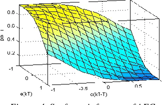
Surfaces inference
The surface of this inference is the most simplified representation of the fuzzy controller. The output is an interpolation made two inputs. Reconciling surface nonlinear control and the language rule is used, will provide hints about the operation of fuzzy control method using surface inference probability bring better marks than other approaches, so close to human reasoning and the nonlinear available. Figure 4 illustrates the curved s urface of the inference rule system is described in Table 2.
Figure 4. Surfaces inference of AFC
From fuzzy inference on the surface, we can easily calculate the probability of the area marked equilibrium, where the error on the queue length is almost zero. On the other hand, the active rule by increased ability to mark packets in areas beyond the equilibrium point where congestion began to be established.
4.3.5.
Fuzzy out variable
To control the decision was final, the output fuzzy sets must be converted into an output value clearly through the defuzzifier allowed. Here, the fuzzy method are central domain of fuzzy output after combined and are shown in formula:
(a) ( )
( )
c k
c
y y dy p
y dy
(b) 1
1
( )
( )
m
j c j j
k m
c j j
y y
p
y
(17)
In particular 𝜇𝑐(𝑦) = 𝑚𝑎𝑥 (𝜇1(𝑦), 𝜇2(𝑦), … , 𝜇𝑁(𝑦) ) is the dependence of y in fuzzy combined C and N is the number of inference rules. Limits of integration allows the formula (17a) corresponds to space medicine and the probability value marking / removal which co ntains y. To reduce the computational process we discretize space Y
into m values and core values obtained as formula (17b)
4.4.
Building sample model
maximum capacity 𝑦𝑚𝑎𝑥 (queue length, link bandwidth) in sample model to establish reference values 𝑦𝑚 corresponding.
This parameter can be set so as to obtain the average delay variation and low latency. For the purpose of keeping instantaneous queue length at a fixed rate, control the flux does not change. Fuzzy control algorithm allows tighter control, avoiding losses and the volatility is not acceptable around the reference point. This contrasts with the traditional AQM algorithms, control the macroscopic behavior of the queue length and packet flow to, they often result in slow response and fluctuations in queue length / store instantaneous load, leading to large latency variability
4.5.
Determine the input and output variables
To work properly, the system should s et the range of values for the input variables to suit the system. The range of values can be determined by testing with different input values for the control system to determine the extent of variation of error in a sampling interval. We choose the value of the error 𝑒(𝑡) and the rate of change of error based on the value added at the time of the error 𝑒(𝑡 − 𝑇) as input on the fuzzy controller. That is, the input is the deviation of the instantaneous output value (y) compared with the reference output value (ym) at two consecutive
time is (t) and (t-T). The expression e(t)
ymy(t) determines the current time and errors e(t- T)
ymy(t- T) was determined time error after a delay time T
(in cycles taken previous sample). Similarly, we need to consider the probability of s election marker / discard the packet 𝑝(𝑡) as the output of the fuzzy controller.
4.6.
Adaptive mechanism
Adaptive mechanism to adjust the output of the K values that mark the appropriate probabilities. When the output value exceeds the reference value, it is necessary to increase K to the probability marks and vice versa. Reduced gradient method applied to the adaptive correction coefficient K output of the fuzzy controller. The process of adjustment is performed according to main structures are referred to as adaptive fuzzy controller according to sample model.
Objects TCP/ IP has transfer function G, sample model with transfer function Gm, the fuzzy controller with transfer
function F. Need to find a rule correction coefficient K so that the difference between the actual value y and the reference value 𝑦𝑚 toward 0 (ε →0). Based on the model in Figure 2, the controller output ratio are defined as follows::
1 m
KFG
y y
KFG
(18)
2
1
(1 )
m y
y KFG KFG
K K KFG K KFG K
(19)
with 1
m y KFG
, 𝑦 ⟶ 𝑦𝑚 then KFG/(1+KFG)1. Therefore, we have:
K K
and K values were
calculated by the formula:
𝐾(𝑡 + 1) = 𝐾(𝑡) − 𝜀(𝑦𝑚− 𝑦(𝑡)) (20) Based on the formula (2:26), the output value exceeds the reference level (𝑦(𝑡) > 𝑦𝑚), the increased value of the coefficient K to increase the value of the packet marking probability. Conversely, when the output values below the reference (𝑦(𝑡) < 𝑦𝑚), the reduced value of the coefficient K to reduce the value of the packet marking probability. Upon reaching steady state, the output value of the reference value (𝑦(𝑡) = 𝑦𝑚) is kept constant 𝐾 value.
5. Improve RED mechanisms by AFC
According to the analysis and evaluation of the traditional AQM mechanisms, as well as analysis and evaluation of the AQM mechanism that uses fuzzy logic, then the improvements AQM mechanisms based on the way long queues around the amendment RED. Therefore, in the construction of improved mechanisms AQM mechanism by AFC adaptive fuzzy control, we continue to choose the improvements represent RED mechanisms based on queue length. AFC Model for FLRED mechanism is based on AFC general model for improving AQM mechanisms is presented in Section 4.1 as follows
5.1.
Fuzzy input variables for FLRED
Using a general improvement model as shown in Figure 2 with T is the sampling period. With Qe(t), Qe(t-T) is misleading the immediate queue length compared to the reference queue TQL in the cycle of sampling and sampling in the previous cycle. This deviation is normalized values in the interval [-1, 1] before putting them into the fuzzy controller by K1 and K2 to the
coefficient determined by the formula (15). The value of the selected language to denote the case of two input
K1.Qe(t), K2.Qe(t-T) was constructed as in Section 4.3.
Context describes how to express the value of linguistic variables as follows:
Statement “deviation queues are positive big (PB)” describes situations where the queue immediate below it than the reference value TQL.
Statement “deviation queues are positive big and deviation queue before is negative small” describes a situation where the queue while the lower than the reference value TQL and it tends to go away in the direction down compared queue with reference values.5.2.
Fuzzy output variables for FLRED
in the buffer zone.
5.3.
Building fuzzy inference rules for FLRED
Set fuzzy inference rules for FLRED are based on the set of values of the input variables Qe(t), Qe(t-T) and output variables p(t) has been built. The rules of the fuzzy controller is based on a formula (14). The system has two inputs, each input has seven linguistic variable value so be 49 fuzzy inference system. Rule form: if (deviation queue is Qe(t)) and (deviation queue before the Qe(t-T)), then the probability of packet marking removal is p(t).
Table 3. Fuzzy rule system of FLRED
𝑝(𝑡) 𝑄𝑒(𝑡 − 𝑇)
NB NM NS ZE PS PM PB
𝑄𝑒(𝑡)
PB VS T Z Z Z Z Z
PM S VS T Z Z Z Z
PS B S VS T Z Z Z
ZE VB B S VS T Z Z
NS H VB B S VS T Z
NM H H VB B S VS T
NB H H H VB B S VS
6. Improve REM mechanisms by AFC
REM mechanism is typical mechanism for AQM mechanisms based on queue length and flow rate to. Therefore, improvement in the AQM mechanism by AFC adaptive fuzzy control, we also choose to improve REM represents AQM mechanisms based on queue length and flow rate to. AFC adaptive fuzzy controller model for the mechanism FLREM builds on AFC general model for improving AQM mechanisms is presented in Section 4.1. Based on this model, the fuzzy controller's AFC FLREM built as follows.
6.1.
Fuzzy input variables for FLREM
AFC for FLREM also based on variable rates (Pr) measure
of congestion as REM algorithm. Therefore, we use two inputs, one for the sample at the current time Pr (t) and a time to form in the previous cycle Pr (t -T). Based on these two input values, the fuzzy controller determines the value of the packet marking probability represents the output of the fuzzy system.
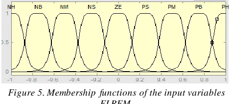
To improve the accuracy we increase the number of membership functions for input and output of the fuzzy system is 9, this will make some inference rules become 81 rules. The downside of the calculation of the price mechanism is the magnitude of the price REM always positive, this is not the actual queue length and flow rate to be much smaller than the reference queue length and bandwidth transmission.
The value of the selected input language to denote the case corresponding to two consecutive times and fuzzy membership functions by a bell-shaped domain nine values: 𝑃𝑟(𝑡) = {𝑁𝐻 , 𝑁𝐵, 𝑁𝑀, 𝑁𝑆, 𝑍𝐸, 𝑃𝑆, 𝑃𝑀 , 𝑃𝐵, 𝑃𝐻 }
and 𝑃𝑟(𝑡 − 𝑇) = {𝑁𝐻, 𝑁𝐵, 𝑁𝑀, 𝑁𝑆, 𝑍𝐸 , 𝑃𝑆, 𝑃𝑀, 𝑃𝐵, 𝑃𝐻 }. In particular: Negative Huge (NH), Negative Big (NB), Negative Medium (NM), Negative Small (NS), Zero (ZE), Positive Small (PS), Positive Medium (PM), Positive Big (PB), Positive Huge (PH).
Figure 5. Membership functions of the input variables FLREM
6.2.
Fuzzy output variables for FLREM
The value of language in the output variable is the singleton value represents the probability nine ascending remove packages from the interval [0,1], is defined as follows:
𝑝(𝑡) = {𝑍 , 𝑇, 𝑉𝑆 , 𝑀𝑆, 𝑆, 𝐵 , 𝑀𝐵 , 𝑉𝐵 , 𝐻}
𝑝(𝑡) = {0,0.125 ,0.25,0.375,0.5,0.635 ,0.75,0.875,1}
In particular, Zero (Z), Tiny (T), Very Small (VS), Medium Small (MS), Small (S), Big (B), Medium Big (MB), Very Big (VB), and Huge (H).
6.3.
Building inference rules for FLREM
Inference system for fuzzy controller consists of a set of If -then rules according to general rules in the form of formula (14). To facilitate the build fuzzy rules, the index for the domain associated values of the input linguistic variables
e(t), e(t-T) is {𝑁𝐻 , 𝑁𝐵, 𝑁𝑀 , 𝑁𝑆 , 𝑍𝐸 , 𝑃𝑆 , 𝑃𝑀 , 𝑃𝐵, 𝑃𝐻} =
{𝜇(𝑒)−4, 𝜇(𝑒)−3, 𝜇(𝑒)−2, 𝜇(𝑒)−1, 𝜇(𝑒)0, 𝜇(𝑒)1, 𝜇(𝑒)2, 𝜇(𝑒)3, 𝜇(𝑒)4}
, the output linguistic variable packet marking probability
p(t) is
{𝐻, 𝑉𝐵, 𝑀𝐵, 𝐵, 𝑆, 𝑀𝑆, 𝑉𝑆, 𝑇, 𝑍} =
{𝜇(𝑝)−4, 𝜇(𝑝)−3, 𝜇(𝑝)−2, 𝜇(𝑝)−1, 𝜇(𝑝)0, 𝜇(𝑝)1, 𝜇(𝑝)2, 𝜇(𝑝)3, 𝜇(𝑝)4}. Fuzzy system is built according to the following general form:
If 𝑒(𝑡) = 𝜇(𝑒(𝑡))𝑖và 𝑒(𝑡 − 𝑇) = 𝜇(𝑒(𝑡 − 𝑇))𝑗 Then
𝑝(𝑡) = 𝜇(𝑝(𝑡))𝑘
In particular: 𝑖, 𝑗 = −4,4̅̅̅̅̅̅, and 𝑘 = 𝑓(𝑖, 𝑗) = 𝑖 + 𝑗, if
𝑖 + 𝑗 > 4 then 𝑓(𝑖, 𝑗) = 4 and if 𝑖 + 𝑗 < −4 then 𝑓(𝑖, 𝑗) = −4.
Based on generalized fuzzy systems, building rules in the following Table 4:
Table 4. Index systems of fuzzy rules for FLREM
p(t) Pr(t-T)
-4 -3 -2 -1 0 1 2 3 4
Pr(t)
4 0 1 2 3 4 4 4 4 4
3 -1 0 1 2 3 4 4 4 4
2 -2 -1 0 1 2 3 4 4 4
0 -4 -3 -2 -1 0 1 2 3 4
-1 -4 -4 -3 -2 -1 0 1 2 3
-2 -4 -4 -4 -3 -2 -1 0 1 2
-3 -4 -4 -4 -4 -3 -2 -1 0 1
-4 -4 -4 -4 -4 -4 -3 -2 -1 0
Based on the domain index values of the linguistic variables for input and output in Table 4, build system for FLREM rules as Table 5. System rules for the fuzzy controller is made up of the control rule of the form:
Table 5. Fuzzy rule system of FLREM
p(t) e(t-T)
NH NB NM NS ZE PS PM PB PH
e(t)
PH S MS VS T Z Z Z Z Z
PB B S MS VS T Z Z Z Z
PM MB B S MS VS T Z Z Z
PS VB MB B S MS VS T Z Z
ZE H VB MB B S MS VS T Z
NS H H VB MB B S MS VS T
NM H H H VB MB B S MS VS
NB H H H H VB MB B S MS
NH H H H H H VB MB B S
7. Simulation and evaluation
Simulation AQM mechanisms are implemented in NS2 [20] software, this software is the most widely used, the research community is trusted and recognized. To objectively evaluate the AQM mechanism, the mechanisms is installed on the same network environment simulation process and are evaluated based on the following criteria: control the queue length and the ability to respond to network changes.
To evaluate, compare the performance of AQM mechanisms must be installed simulation mechanisms in a network model, similar to other network environments, such as the number of nodes, network diagrams, of the connections, applications, bandwidth and latency on each connection. At the same time all the simulation results for AQM mechanisms have processes are described in section 7.1.
The performance of AQM mechanisms will be analyzed and evaluated based on the same general criteria system, is presented in Section 7.2, such as transmission efficiency, packet loss rate in knots bottleneck, the average queuing delay and delay variation.
7.1.
Installing simulation
For the purpose of evaluating the effectiveness of the AQM mechanism using fuzzy controllers AFC, we choose to compare with the original AQM mechanism represents the group (such as RED, REM) and AQM mechanisms
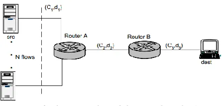
using fuzzy control (such as FEM and FUZZEM) for representing primitive. Therefore, the network model to simulate the mechanism in our model was used to simulate the RED, REM, FEM, FUZREM mechanisms. This model is shown in Figure 6. [1][6][28][29][30][31].
Figure 6. The network model to simulate the AQM
In the model, using the communication protocol TCP / NewReno with congestion window is 240 packets, each packet size of 1000 bytes. Buffer size of all queues is 500 packets. Queue of the bottleneck link is placed between the router-router-A and B, respectively installing AQM algorithms queue manager at bottlenecks, all other links placed queue management mechanism passive. Reference queue length for the mechanism to be set to 200 packets (40% buffer size). Sampling distance is 0.1 seconds, the time taken for the article simulation mechanisms is 100 seconds
7.2.
Evaluation for AQM mechanisms
7.2.1.
Control the queue of AQM mechanisms
The objective of the first simulation scenario is evaluated control queue length of AQM mechanisms in real time. For this purpose, set the number of connections in the source N = 60, the bandwidth and latency of the connection is: (C1, d1) = (15Mbps, 40ms), (C2, d2) = (15Mbps, 5ms ), and (C3, D3) = (30Mbps, 5ms). For the RED queue, simulation set reference queue length 200 package and set two threshold s
minth and maxth corresponding 30% and 70% of the queue length. Congestion notification Mechanism of RED has been made possible by actively setting maxp is 1. Queue reference for FLRED mechanism is set in turn is 100 packages, 200 packages and 300 packages.
Figure 7. Control the queue of RED, FEM and FLRED
When the simulation REM mechanism and the mechanisms to improve REM have used fuzzy controller (FUZREM, FLREM), results in Figure 8, shows that the mechanism controlling REM queue is unstable, whereas the FUZREM and FLREM mechanisms keep the immediate queue length at network nodes is relatively stab le. However, due FLREM nine bell membership function as fuzzy input values so be increased precision makes it possible queue stability better than FUZREM.
Figure 8. Control the queue of REM, FUZREM and FLREM
7.2.2.
Ability to respond of AQM mechanisms
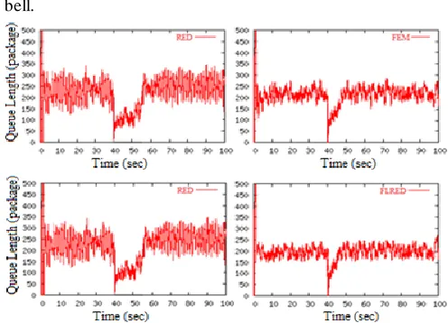
Simulation test the ability to respond of AQM mechanisms when the characteristics of of TCP change through changing the number of connections from 60 to 100 and the access time to the network by stopping the flow in half at time t = 40 seconds and recover in time t = 70 seconds.
Figure 9 and Figure 10 shows, the more reduced the number of connections in the 40th second, the immediate queue length of the mechanism immediately dropped. When increasing the number of TCP flows to 100, the number of packets to the queue and thus increase efficiency queue will increase, leading to delay and delay variation in the queue increases. However, the FEM and FLRED mechanisms, FUZREM and FLREM maintain the queue length fluctuated queue reference value.
Ability to respond the queue management mechanism based on queue length is shown in Figure 9, again shows the adaptation of FEM and FLRED mechanisms when using fuzzy control and the ability to restoration of the status queue FLRED mechanism high when fuzzy system with
bell.
Figure 9,. Ability to respond of RED, FEM and FLRED
Similarly, Figure 10 represents ability to respond the queue management mechanism based on queue length and flow rate to, FLREM have a shorter recovery time than FUZREM.
Figure 10. Ability to respond of REM, FUZREM, FLREM
8. Conclusions
fuzzy controller supports to enhance the management performance of the active queue management mechanisms
References
[1] Athuraliya Sanjeewa, Steven H. Low, Victor H. Li and Qinghe Yin, “REM Active Queue Management”, IEEE Network, 2001
[2] Arash Dana and Ahmad Malekloo, “Performance Comparison between Active and Passive Queue M anagement”, IJCSI International Journal of Computer Science Issues, Vol. 7 Issue 3 No 5, 2010.
[3] Bartek Peter Wydrowski, Techniques in Internet Congestion Control, Electrical and Electronic Engineering Department The University of M elbourne, 2003.
[4] Bart Kosko (1997), Fuzzy Engineering, Prentice Hall, USA. [5] Braden B., Clark D., Crowcroft J., Davie B., Deering S.,
Estrin D., Floyd S., Jacobson V., M inshall G., Partridge C., Peterson L., Ramakrishnan K. K., Shenker S., and Wrocruleski J., (1998), “Recommendations on queue management and congestion avoidance in the internet.” Internet Draf
[6] C. Chrysostomou, A. Pitsillides, G. Hadjipollas, M . Polycarpou, A. Sekercioglu (2004), Fuzzy logic control for active queue management in TCP/IP Networks. 12th IEEE M editerranean Conference on Control and Automation Kusadasi, Aydin, Turkey, (IEEE M ED'04), pp. 2-8
[7] C. V. Hollot, V. M isra, D. Towsley, and W. Gong (2002). Analysis and design of controllers for AQM routers supporting TCP flows. IEEE Trans. on Aut omat. Control, 47:945–959, jun 2002
[8] George J. Klir, Ute St. Clair, Bo Yuan (1997), Fuzzy Set Theory: Foundations and Applications, Prentice Hall, New Jersey, USA.
[9] G.F.Ali Ahammed, Reshma Banu, “Analyzing the Performance of Active Queue M anagement Algorithms”, International journal of Computer Networks & Communications (IJCNC), Vol.2 No.2, 2010
[10] G.Thiruchelvi and J.Raja, “A Survey On Active Queue Management Mechanisms”, IJCSNS International Journal of Computer Science and Network Security, Vol.8 No.12, 2008 [11] Hugang Han, Chun-Yi Su, and Yury Stepanenko (2001),
“Adaptive Control of a Class of Nonlinear Systems with Nonlinearly Parameterized Fuzzy Approximators", IEEE Transactions on Fuzzy Systems, Vol. 9, No. 2, pp.315– 323. [12] I. K. Tabash, M . A. A. M amun and A. Negi “A Fuzzy Logic
Based Network Congestion Control Using Active Queue Management Techniques”, J. Sci. Res. 2 (2), 273-284, 2010 [13] Jang-Hyun Park, Seong-Hwan Kim, Chae-Joo M oon (2006),
“Adaptive Fuzzy Controller for the Nonlinear System with Unknown Sign of the Input Gain", International Journal of Control, Automation, and Systems, Vol. 4, No. 2, pp. 178– 186.
[14] Jasem, H.N., Z.A. Zukarnain, M . Othman and S. Subramaniam (2011), Efficiency and fairness of new-additive increase multiplicative decrease congestion avoidance and control algorithm. J. Applied Sci., 11: 438-449
[15] Jeffrey T. Spooner, M angredi M aggiore, Raúl Ordónez, Kelvin M . Passino (2002), Stable Adaptive Control and Estimation for Nonlinear Systems: Neural and Fuzzy Approximator Techniques, Wiley Interscience, USA. [16] Jyh-Shing Roger Jang (1993), “Adaptive-Network-Based
Fuzzy Inference System”, IEEE Transactions on Systems, M an and Cybernetics, vol. 23(3), pp.665–685.
[17] Jyh-Shing Roger Jang, Chuen-Tsai Sun, Eiji M izutani (1996), Neuro-Fuzzy and Soft Computing: A Computational Approach to Learning and M achine Intelligence, Prentice Hall, USA.
[18] Karl J. Åström, Björn Wittenmark (1995), Adaptive Control, 2nd Edition, Addison-Wesley Publishing, USA.
[19] K.Chitra and G.Padamavathi, “Classification and Performance of AQM -Based Schemes for Congestion Avoidance”, (IJCSIS) International Journal of Computer Science and Information Security, Vol.8 No.1, 2010
[20] Kevin Fall and Kannan, The ns M anual, A Collaboraten between researchers at UC Berkeley, LBL, USC/ISI, and Xerox PARC, 2010.
[21] Long Le, Kevin Jeffay, F. Donelson Smith, “A Loss and Queuing-Delay Controller for Router Buffer M anagement”, Proceedings of the 26th IEEE International Conference on Distributed Computing Systems (ICDCS’06), 2006
[22] Nguyen Kim Quoc, Vo Thanh Tu, “Improving service quality in Internet routers”, Proceedings of the National Workshop on the 14th - Some selected issues of information technology and communications (@), Can Tho, pp. 322-342, 2011
[23] Nguyen Kim Quoc, Vo Thanh Tu, “Performance evaluation of a number of mechanisms active queue management based on queue size and transduced”, Scientific Journal of Hue University, Volume 74A, Number 5, pp. 109-119, 2012 [24] Nguyen Kim Quoc, Vo Thanh Tu, Nguyen Thuc Hai,
“Proposed mechanisms active queue management on high-speed network environment”, Proceedings of the 6th National Conference - Basic research and application of information technology (FAIR), Thua Thien Hue, pp. 108-115, 2013 [25] Nguyen Kim Quoc, Vo Thanh Tu, Nguyen Thuc Hai, “Fuzzy
Logic Control for SFB Active Queue M anagement Mechanism”, ICCASA 2013, Springer, Vol. 128, No. 3, pp. 97-104, 2013
[26] Nguyen Kim Quoc, Vo Thanh Tu, Nguyen Thuc Hai (2014), "Improving control mechanism at routers in TCP/IP networks”, Scientific Journal of EAI Transactions on Context-Aware Systems and Applications, Vol. 1, ISSN 2409-0026, pp. 52-66
[27] Robert Fullér (1995), Neural Fuzzy Systems, Ǻbo Akademi University.
[28] S. H. Low, F. Paganini, and J. C. Doyle (2002). Internet congestion control. IEEE Control Systems M agazine, Feb 2002
[29] V. Santhi and A. M . Natarajan, “Active Queue M anagement Algorithm for TCP Networks Congestion Control”, European Journal of Scientific Research ISSN 1450-216X, Vol.54 No.2, pp.245-257, 201
[30] V. M isra, W. Gong, and D. Towsley (1999), Stochastic differential equation modeling and analysis of TCP windowsize behavior. Technical report, University of M assachusetts, October 1999
[31] V. M isra, W. Gong, and D Towsley. Fluid-based analysis of a network of AQM routers supporting TCP flows with an application to RED. In SIGCOM M , pages 151–160, August 2000