PARTIAL SUBSTITUTION OF DIESEL
IN ENGINE-GENERATOR SETS WITH
WOOD BASED PRODUCER GAS
L. KUMARARAJADepartment of Mechanical Engineering, Pondicherry Engineering College, Puducherry-605 014, India
Ph. No. 9486008622; e-mail: [email protected]
R. SETHUMADHAVAN Institute for Energy Studies, Anna University,
Chennai-600 025, India e-mail: [email protected]
ABSTRACT
Electrical power generation by Diesel engine + electrical Generator (DG) sets consumes precious fossil fuels. In the present work, performance of two different DG sets of 3 kW and 100 kW ratings are compared when they were additionally supplied with wood derived Producer Gas (PG) generated in a gasifier. The PG was cleaned and cooled before it was supplied to the DG sets. The salient feature of 3 kW system is that the PG does not come into direct contact with water during cleaning and cooling, whereas it does so in 100 kW system. In the experiments, both DG sets were operated in fully diesel and dual fuel (PG + diesel) modes. Diesel Consumption Rate, Diesel Replacement Percentage, Specific Diesel Consumption, Electrical Conversion Efficiency were calculated for the DG sets. Because of certain improved features and operating conditions, the 100 kW DG set could be operated more efficiently than the 3 kW DG set. Hence, electrical power generation by DG set using PG + diesel can be achieved more economically at higher power ratings.
Keywords: Biomass gasifier, Diesel engine-electrical Generator set, producer gas.
1. Introduction
Electrical power generation by Diesel engine + electrical Generator (DG) set is one of the methods resorted to by industries and commerce when State Electricity Board’s power supply is disrupted. The cost of electricity generated by this method is as high as Rs.16/kWh. This method has certain shortcomings especially those associated with the fuels used in DG sets. They are:
• The costs of liquid fuels like High Speed Diesel, Light Diesel Oil, Furnace Oil, etc., used in DG sets are high. Large chunks of these fuels are distilled from imported crude oil (130 MMt/year in India).
• The costs of gaseous fuels like Liquefied Natural Gas, Compressed Natural Gas, etc., which can also be used in DG sets, are also high. Moreover, a large portion of India’s total gas consumption is only imported. • As these liquid and gaseous fuels are fossil fuels, their reserves are finite.
• Fluctuations in oil and gas prices affect very much the cost of products and services derived from them. • Fuel supply shortages and non-availability are also faced sometimes.
• Air pollution and green-house gas emissions occur due to the use of fossil fuels in engines.
of diesel substitution was found to be 70% [6]. For a 4.5 kW diesel engine, when operated at 80% load, a diesel replacement rate of 68% was reported [7].
In the present work, a complete performance analysis of a 3 kW gasifier + DG system developed in the lab and a general performance testing of a 100 kW gasifier + DG system established in an institution were done under PG + diesel operation. In the former, PG was generated in a 5 kg/h capacity gasifier but in the latter, it was generated in an 80 kg/h capacity gasifier. In both the gasifiers, wood pieces were used as feedstock. The comparison of performances of 3 kW and 100 kW DG sets has been done to find out whether all performance parameters change in the same pattern or not.
2. Methodology
2.1. Description of 3 kW system
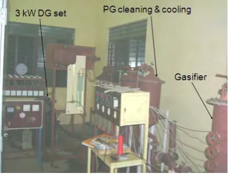
The 3 kW gasifier + DG system used for conducting a complete analysis consists of a gasification system and a 3 kW DG set. The gasification system consists of gasifier, air blower, cyclone separator, dust filter, gas cooler, adsorber, and associated instruments. The DG set consists of a diesel engine, PG-air mixer, electrical generator, resistance load bank, and associated instruments. The photographic view of the system is shown in fig. 1. The motorized blower supplies air to the gasifier. The gasifier is a packed bed, downdraft and throat type. The engine suction also helps the air flow through the gasifier. A valve regulates air supply from the motorized blower. Air enters the gasifier through air inlet pipe at the top. The wood pieces are fed through the feeding port, which is also provided at the top of gasifier. The gasifier is lined inside with refractory cement to withstand high temperature. The ash accumulated in the ash chamber during operation of the gasifier is removed through an ash port.
Fig. 1. Experimental gasifier-engine-generator system
The PG exiting the gasifier is passed to a cyclone separator to remove coarse dust particles. Then it is sent to a dust filter for filtering out finer particles from PG. After the PG is cleaned, it enters a gas cooler. The cooled PG is then passed to an adsorber for final tar removal. The dust particles and (or) condensate segregated from PG are collected directly below each component by means of gas tight dust collectors. The PG does not come into direct contact with water anywhere in the system but it is dry cleaned in the various components mentioned above. Due to which, there is no generation of contaminated effluent water in the gasification system and the question of its safe disposal does not arise.
Table 1. Specifications of 3 kW gasifier + DG system
Type of gasifier Packed bed, downdraft, throat type Max. wood feed rate 5 kg/h
Diesel engine Electrical Generator
Type Vertical, 4 stroke, direct injection, water cooled
Type Direct coupled to engine, 1 - φ, A.C., 50 Hz Compression
ratio
18.5 :1 Rated O/P 3.5 kVA
Efficiency 90% Rated O/P 3.7 kW, 1500 rpm Voltage 230 V
Bore diameter 84.5 mm Current 15 A
Stroke 112 mm Speed 1500 rpm
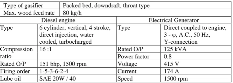
2.2. Description of 100 kW system
The 100 kW gasifier + DG system used for conducting a general test consists of a gasification system and a 100 kW DG set. The bigger system contains all the basic components of smaller system but with certain improved features. In bigger system, PG is wet cleaned and cooled by direct contact with water in several stages before supplying it to DG set to ensure thorough cleaning and cooling. The contaminated water must be discharged out of the system once in every 20 hours of operation. The 3-phase electrical power generated by the system is supplied to electrical sub-station of the institution. The major specifications of 100 kW gasifier + DG system are given in Table 2.
Table 2. Specifications of 100 kW gasifier + DG system
Type of gasifier Packed bed, downdraft, throat type Max. wood feed rate 80 kg/h
Diesel engine Electrical Generator
Type 6 cylinder, vertical, 4 stroke, direct injection, water cooled, turbocharged
Type Direct coupled to engine, 3 - φ, A.C., 50 Hz, Y-connection Compression
ratio
16 :1 Rated O/P 125 kVA
Power factor 0.8 Rated O/P 151 bhp, 1500 rpm Voltage 415 V
Firing order 1-5-3-6-2-4 Current 174 A
Lube oil SAE 20W / 40 Speed 1500 rpm
2.3. Experiments on 3 kW system
First, an elaborate experiment was conducted on 3 kW gasifier + DG system. Initially, the DG set was tested in fully diesel mode. The experiment was conducted from no load to maximum load. For every load condition, (i) diesel consumption rate, (ii) engine airflow rate, (iii) speed, (iv) voltage, (v) current, and (vi) electrical power were measured. Next, the DG set was tested in dual fuel (PG + diesel) mode. For that purpose, the gasifier was started and operated by supplying air from the blower. The PG was passed through cleaning and cooling train and was flared at the exit of adsorber for about 10 minutes to bring the gasification system to steady state condition. In the meantime, the DG set was started in fully diesel mode and once its operation became stable, the PG was admitted gradually to the engine through the PG-air mixer. For every load condition, (i) diesel consumption rate, (ii) engine air flow rate, (iii) PG flow rate, (iv) speed, (v) voltage, (vi) current and (vii) electrical power were measured in the DG set.
After the test, the PG flow to DG set was cut off, followed by diesel. The gasifier was then stopped and was cooled. The residual feed stock left in the gasifier was cleared out. The dust particles and (or) condensate segregated from PG were removed from gas tight dust collectors.
2.4. Tests on 100 kW system
3. Results and Discussion 3.1 Performance of 3 kW system
From the various measurements, the important performance parameters of the DG set were calculated. As PG has distinct physical and chemical properties with respect to diesel, its usage in diesel engine has resulted in variations in the entire DG set operating parameters.
3.1.1. Diesel Consumption Rate (DCR)
The DCR of 3 kW DG set, which is the quantity of diesel consumed per unit time, was calculated for both fully diesel operation and dual fuel operation at various loads. The DCR varied between 0.45 l/h and 1.23 l/h in fully diesel operation. In dual fuel mode, the DCR got reduced and it varied between 0.17 l/h and 0.75 l/h. The DCR at various electrical loads are shown in fig. 2for both fully diesel and dual fuel. The decrease in DCR in dual fuel mode is a result of the partial substitution of diesel by producer gas. Consequently, the extent of substitution or replacement of diesel becomes a parameter of interest.
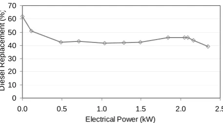
Diesel Replacement Percentage in the DG set during dual fuel operation has been evaluated at various loads and it is shown in fig. 3. At no load condition, a higher diesel replacement was achieved. Since PG flow rate remained same, at higher loads the thermal energy released by its combustion was insufficient to take up the increased load. Hence, the additional load was borne by more diesel combustion resulting in reduced Diesel Replacement Percentage at higher loads.
Fig. 2. Diesel Consumption Rates at various electrical loads
Fig. 3. Diesel Replacement Percentage in dual fuel mode
3.1.2. Specific Diesel Consumption (SDC)
SDC is defined as the amount of diesel required for a unit electrical energy output. Fig. 4 shows SDC in fully diesel and dual fuel modes of operation at all electrical loads. In dual fuel mode, SDC was lesser due to the supply of PG.
0.0 0.2 0.4 0.6 0.8 1.0 1.2 1.4
0.0 0.5 1.0 1.5 2.0 2.5 3.0
Electrical Power (kW)
D
ie
s
el
C
on
s
um
pt
io
n R
at
e
(l
/h
)
Fully diesel mode Dual fuel mode
0 10 20 30 40 50 60 70
0.0 0.5 1.0 1.5 2.0 2.5
Electrical Power (kW)
D
ies
el
R
e
pl
ac
em
ent
(
%
Fig. 4. Specific Diesel Consumption at various electrical loads
3.1.3. Electrical conversion efficiency
It is defined as the ratio of electrical power output to thermal power input by combustion of fuel in the engine. From fig. 5, it is clear that there is substantial decrease in the conversion efficiency when DG set was run in dual fuel mode. It can be improved by (i) certain modifications in engine design like valve timing and injection timing adjustments when PG is used as one of the fuels and (ii) increasing the calorific value of PG by removing inert gases present in it.
Fig. 5. Electrical Conversion Efficiency at various electrical loads
3.2. Performance of 100 kW system
The performance of 100 kW gasifier + DG system was better when compared to that of 3 kW gasifier + DG system. It was due to the use of 6-cylinder, turbocharged, diesel engine coupled with high efficiency, 3 phase electrical generator. Furthermore, thoroughly cleaned and cooled PG was supplied to drive the DG set.
3.2.1. Diesel Consumption Rate (DCR)
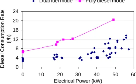
The plot of DCR vs. electrical power of the 100 kW DG set is shown in fig. 6 for both fully diesel and dual fuel modes of operation. As the engine rating was 151 bhp, its DCR was higher when compared to that of 3 kW DG set. Diesel Replacement Percentage in dual fuel operation of the DG set at various loads is shown in fig.7. It was hovering between 60 % and 70% throughout the test period as against 40% and 63% diesel replacement of 3 kW system.
0 1 2 3 4 5
0.0 0.5 1.0 1.5 2.0 2.5 3.0
Electrical Power (kW)
S pec if ic D ies el C on s um p ti o n (l /k W h )
Fully diesel mode Dual fuel mode
0 5 10 15 20 25
0.0 0.5 1.0 1.5 2.0 2.5 3.0
Electrical Power (kW)
E le c tr ic al C onv er s io n E ffi c ie n c y ( % )
Fully diesel mode Dual fuel mode
4 8 12 16 20 24 D ies el C ons um pt ion R at e (l /h )
Fig. 7. Diesel Replacement Percentage in dual fuel mode for 100 kW DG set
3.2.2. Specific Diesel Consumption (SDC)
The SDC of 100 kW system in fully diesel and dual fuel modes of operation are shown in fig. 8 at various electrical loads. As expected, SDC was lesser in dual fuel mode due to the supply of PG than that in fully diesel mode. A comparison of figs. 4 and 8, indicate that the SDC of 100 kW system is just 50% of SDC of 3 kW system in dual fuel mode.
Fig. 8. SDC of 100 kW DG set at various electrical loads
3.3. Comparison between 3 kW and 100 kW DG sets
The performance tests on two different DG sets were conducted and the important results are shown in Table 3. It is evident that the performance of 100 kW DG set has been better than that of 3 kW DG set.
Table 3. Comparison of results between 3 kW and 100 kW DG sets
Parameters 3 kW DG set 100 kW DG set
Diesel Replacement (%) 40 – 63% 60 – 70%
SDC in fully diesel mode at max. load (l/kWh) 0.5 0.42 SDC in dual fuel mode at max. load (l/kWh) 0.3 0.15
The advanced features of the 100 kW DG set like (i) suction blowers to draw the PG through the system, (ii) elaborate cleaning and cooling system with the help of water, (iii) turbo-charging of the engine with PG + air mixture at a higher pressure, etc. are responsible for its better performance. However, the auxiliary power consumed by the suction blowers and the generation of contaminated effluent water after cleaning and cooling of PG are the factors of concern. In the case of 3 kW DG set, even though the performance parameters are less favourable, there was no generation of contaminated water as PG was only cleaned and cooled by water indirectly.
4. Conclusions
Two DG sets of 3 kW and 100 kW ratings were analysed for their performance in fully diesel and dual fuel modes. For operating in dual fuel mode, wood pieces were gasified in downdraft biomass gasifiers and the PG was cleaned and cooled before supplying it to the engines. Both the DG sets showed similar performance with respect to DCR, Diesel Replacement Percentage, SDC and probably Electrical Conversion Efficiency also.
0 10 20 30 40 50 60 70 80
0 10 20 30 40 50 60
Electrical Power (kW)
D
ies
el
R
e
pl
ac
em
e
nt
(
%
)
0.00 0.10 0.20 0.30 0.40 0.50 0.60 0.70
0 10 20 30 40 50 60
Electrical Power (kW)
S
p
ec
if
ic
D
ies
el
C
ons
um
p
ti
on
(
l/
k
W
h
)
DCR in dual fuel operation was comparatively lower to that in fully diesel operation for both DG sets under all electrical loads.
The values of Diesel Replacement Percentages were also significant in both the DG sets. However, Diesel Replacement Percentage was higher in 100 kW DG set than in 3 kW DG set.
The SDC in dual fuel mode was lower than that in fully diesel mode for both the DG sets. Again, SDC of 100 kW DG set was lesser than that of 3 kW DG set at all electrical loads.
On the basis of above factors, it may be expected that Electrical Conversion Efficiency of a higher rating DG set would be more than that of a lower rating DG set at any load. Electrical power generation of 100 kW and above using DG sets in dual fuel mode (PG + diesel) has been proved to be economically beneficial. Thus, biomass gasifier based electrical power generation is an attractive option for both decentralized and captive power generation.
Acknowledgement
The first author thanks with gratitude the authorities of Pondicherry Engineering College, Puducherry, for the extensionof facilities to conduct this research.
References
[1] Wander, P. R., Altafini, C. R., and Barreto, R. M., “Assessment of small sawdust gasification unit,” Biomass & Bioenergy, Vol. 27, 2004, pp. 467-476.
[2] Sridhar, G., Sridhar, H. V., Dasappa, S., Paul, P. J., Rajan, N. K. S., Shrinivasa, U., and Mukunda, H. S. “Technology for gasifiying pulverized bio-fuels including agricultural residues,” Energy for Sustainable Development, Vol. 3, July 1996, pp. 9-18.
[3] Bhattacharya, S. C., San Shwe Hla, and Hoang-Luang Pham, “A study on a multi-stage hybrid gasifier-engine system,” Biomass and Bioenergy, Vol. 21, 2001, pp. 445-460.
[4] Singh, R. N., Singh, S. P., and Pathak, B. S., “Performance of Renewable fuel based CI engine,” Agricultutural Engineering International: The CIGR E-journal. Manuscript EE 0014 Vol. IX April 2007.
[5] Uma, R., Kandpal, T. C., and Kishore, V. V. N., “Emission characteristics of an electricity generation system in diesel alone and dual fuel modes,” Biomass and Bioenergy, Vol. 27, 2004, pp. 195-203.
[6] Ramadass, A. S., Jayaraj, S., and Muralidharan, C, “Power generation using coir pith and wood derived producer gas in diesel engines”,Fuel Processing Technology, Vol. 87, October 2006, pp. 849-853.