SIMULATION AND COMPARISON OF
SINGLE PHASE MULTI HIGH LEVEL
INVERTER FOR DIFFERENT LOADS
V V DURGA PRASAD REDDY
P G Scholar
B V C Engineering College, Odalarevu Andhra Pradesh, India
Prof J V G RAMA RAO
Department of EEE
B V C Engineering College, Odalarevu Andhra Pradesh, India
Abstract -Multi-level inverters have tremendous applications in the power industry. They present a new set of features that are well suited for use in reactive power compensation. They typically synthesized voltage waveform reduces harmonic content. It may be easier to produce a high-power, high-voltage inverter with the multilevel structure and also voltage stresses are controlled. Increasing the number of voltage levels in the inverter without requiring higher ratings on individual devices can increase the power ratings. The unique feature of the multilevel inverters is to provide high switching frequencies with low switching losses. This paper gives an insight into SPWM Two level inverter, diode clamped, flying capacitor, cascaded H-Bridge multilevel inverters. Detailed analysis of these inverters has been carried out and compared to know how the voltage stresses and switching losses reduced. In this paper work the simulation of various multilevel inverters using MATLABSIMULINK is done and the waveforms are obtained.
Index Terms – SPWM, H-Bridge, diode clamped, flying capacitor multilevel inverters. 1.Introduction
An Inverter converts DC input Voltage into Ac Output Voltage of variable magnitude and frequency [11]. The basic Bridge Inverters suffers many of the disadvantages from following drawbacks. They have high ripple content in the output. The series parallel operation of the switching devices for high power and high voltage applications is a difficult task. Switching devices for higher ratings are difficult to fabricate. Harmonic content is high.
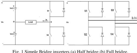
2. Simple Bridge Inverters
Two level inverter is the simplest topology, which is used to produce a two level square wave output waveform.
Fig. 1 Simple Bridge inverters (a) Half bridge (b) Full bridge.
A center tapped voltage source supply is needed in such a topology. It may be possible to use a simple supply with two well matched capacitors in series to provide the center tap. The full bridge topology is used to synthesize a three level square wave Output waveform
Table I Load Voltage with Corresponding Conducting Switches
Load Voltage with corresponding conducting switches
Half Bridge inverter Full Bridge inverter
Conducting Switches
Output Voltage Vao
Conducting Switches
Load Voltage Vab
S1 +Vs/2 S1 , S4 +Vs
S2 -Vs/2 S2, S3 -Vs
S1, S2 or S3, S4 0
3. Multilevel Inverters
Generally, harmonics may be divided into two types:1) Voltage harmonics and 2) Current harmonics[2]. Current harmonics are usually generated by harmonics contained in voltage supply and depend on the type of load such as resistive load, capacitive load and inductive load. Load harmonics can cause the over heating of the magnetic cores of transformer and motors. On the other hand, source harmonics are mainly generated by power supply with non-sinusoidal voltage waveform [1].
The Multilevel Voltage Source Inverter is recently applied in many industrial applications as AC power supplies, static VAR compensators, drive systems, etc. One of the significant advantages of multilevel configuration is the harmonic reduction in the output waveform without increasing switching frequency or decreasing the inverter power output. As the number of levels reach infinity, the output THD approaches zero.
Types of Multilevel Inverters
There are several ways to achieve multilevel inverters. The main topologies are 1) Diode clamped inverters
2) Flying capacitors inverter 3) The cascade inverter
3.1 Diode clamped inverters
An m-level diode clamped inverter typically consists of (m-1) capacitors on the dc bus and produces m levels of phase voltages. An m-level inverters leg requires (m-1) capacitors, 2(m-1) switching devices and (m-1) (m-2) clamping diodes.
Principle of Operation
Table 2 Load Voltages with Corresponding Conducting Switches for Diode Clamped 5-Level Inverter
Features
1) High Voltage rating required for blocking diodes 2) Unequal device rating
3) Capacitor voltage unbalance
The main disadvantage is Excessive clamping diodes are required when the number of levels is high.
3.2. Flying capacitors inverter
Fig.3 illustrates the fundamental building block of a single-phase full bridge flying-capacitor inverter. Assuming that each capacitor has the same voltage rating, the series connection of capacitors indicates the voltage level between the clamping points [5,6]. The voltage level defined in the flying-capacitor converter is similar to that of the diode-clamped type converter. The phase voltage of an m-level converter has m levels including the reference level, and the line voltage has (2m-1) levels.
Fig. 2 Diode Clamped Multilevel Inverter Fig. 3 Flying capacitors inverter
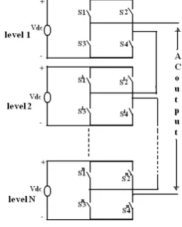
3.3 The cascade inverter
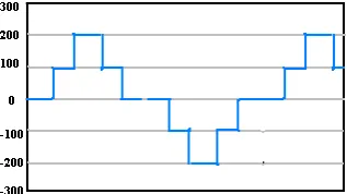
Fig.4 shows the power circuit for one phase of multi level inverter. The resulting voltage ranges from +Vdc to -Vdc and the staircase are nearly sinusoidal, even without filtering [8].
Va0 Sa1 Sa2 Sa3 Sa4 Sa1’ Sa2’ Sa3’ Sa4’
4Vdc ON ON ON ON OFF OFF OFF OFF 3Vdc OFF ON ON ON ON OFF OFF OFF
2Vdc OFF OFF ON ON ON ON OFF OFF Vdc OFF OFF OFF ON ON ON ON OFF
Applications
1) Reactive power compensator 2) Back-to Back intertie
3) Utility Compatible Adjustable Speed Drives
4. Sinusoidal PWM Inverter
A Single phase PWM inverter consists of a PWM generator, a universal 2-arm bridge and a dc source as shown in Fig 6. In this PWM generator triangular carrier wave is compared with sinusoidal modulating wave of frequency 50 Hz. A single phase SPWM inverter is simulated for different values of carrier frequency and their output waveforms have been plotted [2,3].
Fig 6 Single phase SPWM inverter
Table 3 Comparison of SPWM Inverter
Carrier frequency
3rd
harmonic content
5th
harmonic content
7th
harmonic content
9th harmonic
content
100 0.649 0.1686 0.1641 0.2144
150 0.1774 0.4245 0.2894 0.3175
250 0.0155 0.0174 0.1719 0.3615
400 0.0014 0.0018 0.0016 0.0019
500 0.0011 0.0012 0.0015 0.0014
5. Multilevel Inverter Simulation
Load harmonics can cause the over heating of the magnetic cores of transformer and motors. On the other hand, source harmonics are mainly generated by power supply with non-sinusoidal voltage waveform. The Multilevel Voltage Source Inverter was introduced as a solution to increase the converter output voltage above the voltage limits of classical semiconductors [4]. As the number of levels are increased , the synthesized output waveform has more steps which produce a staircase wave that approaches the desired waveform. Here the proposed system mentioned one of the multilevel inverter i.e., diode clamped; flying capacitor type and cascade type five level multilevel inverter. The SIMULINK diagrams are shown below:
Table 4 Comparison between Three Different Five Level Inverter Topologies
Multilevel inverter Diode
clamped
Flying
Capacitor H-Bridge
Main controlled
switches 8 8 8
Auxiliary controlled
switches 0 0 0
Diodes 20 8 8
Capacitors 4 10 2
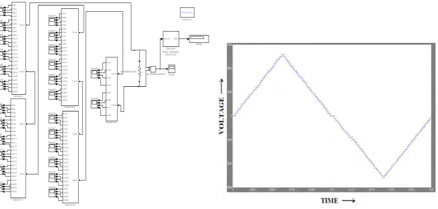
From the above table 4, the numbers of switching devices are reduced greater in H-bridge inverter using auxiliary controlled switch. When the switching devices are reduced the switching losses also reduced then the efficiency of the inverter is improved. In this paper, he proposed model simulated different levels of inverters and compared to other level inverters. Here a simulated upto 53-level. The below simulink diagrams and results shows the different high level (like 35 and 53) inverters outputs.
Fig.8 simulink diagram for Cascade H-bridge type ‘35’ level inverter Fig 9. Output waveform for 35 level inverter
Fig.10 simulink diagram for Cascade H-bridge type ‘53’ level inverter Fig 11. Output waveform for 53 level inverter
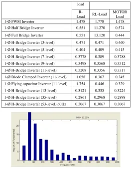
6. Simulation Results Discussion
From the above simulation results the total harmonic distortion (THD) is determined and tabulated below for various multi level inverters with conventional inverters also.
load
R-Load RL-Load
MOTOR Load
1-Ø PWM Inverter 1.478 1.778 1.478
1-Ø Half Bridge Inverter 0.551 11.270 0.574
1-Ø Full Bridge Inverter 0.551 13.120 0.444
1-Ø H-Bridge Inverter (3-level) 0.471 0.471 0.460
1-Ø H-Bridge Inverter (5-level) 0.404 0.409 0.415
1-Ø H-Bridge Inverter (7-level) 0.3778 0.389 0.3788
1-Ø H-Bridge Inverter (9-level) 0.3498 0.3568 0.3512
1-Ø H-Bridge Inverter (11-level) 0.3208 0.3356 0.3317
1-Ø Diode Clamped Inverter (11-level) 1.058 0.367 0.345
1-Ø Flying capacitor Inverter (11-level) 1.754 0.446 0.329
1-Ø H-Bridge Inverter (13-level) 0.3121 0.335 0.3224
1-Ø H-Bridge Inverter (35-level) 0.2861 0.2968 0.2898
1-Ø H-Bridge Inverter (53-level),60Hz 0.3067 0.3067 0.3067
Fig 12. THD for 53 level inverter
7. Conclusion
In this paper the advantages and applications of multilevel inverters are mentioned and a detailed description of different multilevel inverter topologies is presented and also concluded that controlling of voltage magnitude of inverter by PWM technique is most efficient when compared with other techniques. A brief Comparison of different multilevel inverter topologies is given and we observe that new simplified multilevel inverter requires fewer number of components to synthesize the given stair case voltage waveform which in turn makes it cost effective and less complex. The conventional inverter eliminates the 3rd harmonic content and the high level 35 & 53-level inverters eliminate the 5th harmonic in the output voltage.
From the simulation results, concluded that the non linear loads have reduced total harmonic distortion (THD) in multi level inverters as compared to other conventional inverters. Then the reduced harmonic distortion reduces the switching losses for higher frequency applications. Then the power transfer capability is increased for non linear loads
Acknowledgement
V V Durga Prasad Reddy received his B. Tech degree in Electrical and Electronics Engineering from B V C Institute of science and technology, Batlapalem, Amalapuram in 2008, the M.TECH. degree in POWER ELECTRONICS from B.V.C. Engineering college, Odalarevu, in 2012. At present, He is engaged in “Simulation and Comparison of Single Phase Multi High Level Inverter For Different Loads”.
High voltage testing, Electro-magnetic field computations, HVDC Transmission systems , Power converters , Wavelets . He has published research papers in national and international conferences
References
[1] J. Rodrigues, J.S. Lai, and F. Z. Peng, “Multilevel inverters: a survey of topologies, controls and applications,” IEEE trans. Ind.
Electron., vol. 49, no. 4, pp. 724-738, Aug 2002.
[2] L. M. Tolbert and T. G. Habetler, “Noval multilevel inverter carrier based PWM-method” IEEE trans. Ind. Appl.,vol. 35, no.5, pp.
1098-1107, sep./oct.1999.
[3] G. Carrara, S. Gardella, M. Marchesoni, R. salutary, and G. Sciutto, “A new multilevel PWM method: a theoretical analysis,” IEEE
trans. Power electron.,vol. 7, no.3, pp. 497-505, Jul.1992.
[4] J. W. Kolar H. Ertl and F. C. Zach, “Influence of the modulation method on the conduction and switching losses in the multilevel
inverter system,” IEEE trans. Ind. Appl.,vol. 27, no.6, pp. 1057-1063, Nov/Dec.1991.
[5] J. N. Chiasson, L. M. Tolbert, K. J. McKenzie, Z. Du, “A New Approach to Solving the HarmonicElimination Equations for a
Multilevel Converter,” IEEE Industry Applications Society Annual Meeting,October 12-16, 2003, Salt Lake City, Utah, pp. 640-645.
[6] L. M. Tolbert, “New Multilevel Carrier-Based Pulse Width Modulation Techniques Applied to a Diode-Clamped Converter for Use as
a Universal Power Conditioner,” Ph.D. Dissertation, Georgia Institute of Technology, 1999, pp. 76-103.
[7] Klabunde, Y. Zhao, and T. A. Lipo, “Current control of a 3 level rectifier/inverter drive system,” in Conference Record 1994 IEEE IAS
Annual Meeting, 1994, pp. 2348–2356.
[8] W. Menzies, P. Steimer, and J. K. Steinke, “Five-level GTO inverters for large induction motor drives,” IEEE Transactions on
Industry Applications, vol. 30, no. 4, pp. 938–944, July 1994.
[9] J. Vassallo, P. W. Wheeler, and J. C. Clare, “Optimal waveform generation for utility-connected multilevel converters,” in European
Power Electronics Conference, September 2003.
[10] T. Kato, “Sequential homotopy-based computation of multiple solutions for selected harmonic elimination in PWM inverters,” IEEE
Transactions on Circuits and Systems - 1: Fundamental Theory and Applications, vol. 46, no. 5, pp. 586–593, May 1999.