Design of a Heavy Medium Separator
OKPALA, ALEXANDER NWACHUKWU, PhD
DEPARTMENT OF MECHANICAL ENGINEERING,
FACULTY OF ENGINEERING, NIGER DELTA UNIVERSITY,
WILBERFORCE ISLAND, BAYELS A STATE, NIGERIA.
ABSTRACT
The design of a laboratory size heavy medium separator was carried out. This was done sequel to the need for a locally available and affordable laboratory heavy medium separator for metallurgy students in developing economies. The separator was successfully designed and proper material selection achieved. The separator has since been fabricated and put to effective use.
Key Word; separator, heavy medium, comminution, minerals, gravity, float, sink
1.0 INTRODUCTION
The design of the heavy metal separator is based on the principle mixture of comminuted materials with different specific gravity is charged into a vessel containing any suitable liquid; the material whose specific gravity is greater than that of the liquid will sink while those with specific gravity is less than that of the liquid will float. Hence it is imperative that if the vessel is rotating, due to the whirling action impacted on the mixture, minerals with higher specific gravity than the liquid would move to the walls of the containing vessel while those of lower specific gravity would segregate to the centre portion of the containing vessel and fall out through openings on the side walls and the central outlet of the containing vessel respectively.
2.0 SCOPE OF DESIGN
This design work was done using components that are readily available to ensure its workability. For instance, the maximum length that would be handled by the wood drilling machine available is 430mm; therefore the length of the separator (shaft) selected to be 430mm. the motor available for the separator has a power rating of 1Hp (0.746Kw) and a speed of 1440rpm.
The separator is specifically designed to concentrate a maximum of 5kg of minerals with specific gravity less than or equal to that of iron ore (5.2 - 5.3).
3.0 DETERMINATION OF THE LOAD TO BE CARRIED BY SHAFT
For a mineral with specific gravity (S.G.) of 5.3, its density = 5.3 x 1000kg/m3
From Volume
5kg of the mineral will occupy a volume of
0.000943m .
But it is given that for effective separation, the volumetric ratio of water to ore should be about 3:1 [Kelly and Spottiswood (1982)].
Therefore for 5kg of ore occupying a volume of 0.000943m3, the water occupies a volume of 0.000943 x 3 = 0.00283m3
From mass = volume x Density,
Mass of water required to separate 5kg of ore
= 0.00283 x 1000 = 2.83kg
Mass of slurry = mass of ore + mass of water
= 5kg + 2.83kg
= 7.83 ≈ 8.0kg (to allow for over loading)
This mass is to be distributed over a length of 430mm; therefore this gives a uniformly distributed load of
8.0
0.43Kg/m 18.6Kg/m 186N/m
For the purpose of power transmission to the shaft that would carry the separator, a pulley weighing 1.773kg with a sheave diameter of 160mm was selected for trial design.
Figure 1: Free Body Diagram of the conceptual arrangement of the component parts
3.1 Determination of the Support (Bearing) Reactions
+∑MB = 0
17.73 (0.05) – 79.98 (0.265) + RE (0.53) = 0 and RE = 38.32N
+∑F= 0
‐ 17.73 + RB – 79.98 + RE = 0
RB = 79.98 + 17.73 – 38.32 = 59.39N
E
186 N/m
17.73 N
RB RE
B
A C D F
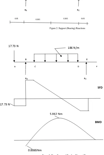
Figure 2: Support (Bearing) Reactions
Figure 3: Shear Force and Bending Moment Diagrams
17.73 N 79.98 N
0.265
RB RE
0.265 0.05 0.05
E
186 N/m
17.73 N
RB RE
B
A C D F
17.73 N
5.862 Nm
0.8865Nm
BMD
3.2 Determination of the maximum Bending Moment
From the SPD it is seen that the point of zero shear force (i.e. point of maximum bending moment) falls in the region between C and D. Equating the shear force equation for this region to zero, we obtain;
Fx= -17.73 + 59.39 – 186 (X-0.1) = 0
X . . 0.324m from A
Substituting this value of X into the bending moment equation for this region (between C and D),
M 17.73 0.324 59.39 0.324 – 0.05 – 186 . – .
Mmax = 5.862 Nm.
4.0 DESIGN OF SHAFT
Since the motor available has a power rating of 1Hp (0.746kw) speed of 1440rpm and a driving sheave (pulley) diameter of 80mm. the speed of the shaft could be calculated since the sheave diameter of the driven (pulley) to be attached to the shaft is known to be 160mm from the relation
n1D1 = n2D2
Where n1 and n2 are the motor and the shaft speeds respectively
D1 and D2 are the motor and pulley attached to the shaft, sheave diameter respectively.
Shaft Speed n2
720 rpm
Also, since a factor of 0.1 is allowed for losses in power for transmission from motor to shaft [Cherkassky (1977)], the power rating of the shaft in kw
= 0.746 – 0.746 x 0.1
=0.6714kw
The torsional moment acting on the shaft
M [Hall et al(1980)]
Where P = shaft power rating in kw
V = shaft speed in rpm
M . 8.905
The shaft diameter (hollow) is derived from the formula
d π [Hall et al(1980)]
Where Ss = Maximum shear stress (allowable)
Mb = Mmax = bending moment in Nm
Mt = Torsional moment in Nm
K = di/do
Kt = combined shock and fatigue factor applied to torsional moment
But, Mb = 5.862 NM
Mt = 8.905NM
K = 0.6 (chosen from table) Kb = 2.0 (chosen from table)
Kt = 2.55(chosen from table)
Ss = 1.65 x 10⁶N/m2 for shaft material [Iroko type of hardwood: Tyler(1980)]
Therefore,
d . . . . ..
d3 = 9.0626 x 10⁻⁵m3 and Shaft diameter d, = 0.0449m ≈ 45mm.
4.1 Determination of the diameter of the Cylindrical Separator attached to the shaft
Taking a fillet radius r, of 3mm and a stress concentration factor due to bending, K= 2. The ratio 0.067
From stress concentration factor graph [Spotts (1988)], these two values gives a corresponding D/d ratio =2.
Where D = diameter of cylindrical separator
D = diameter of shaft
D = 2d = 2 x 45mm = 90mm.
4.2 Determination of the Critical speed of shaft
The fundamental critical speed for a shaft on two supports is as follows:
f
π
⋯
⋯ cycles/sec
Where W1, W2, etc the weights of the rotating body
Y1, Y2 etc represents the static deflection of the weight
g=gravitational constant = 386m/sec [Spotts (1988)]
4.3 Determination of Static Deflections Due to Weights
Figure 4: Free body diagram of Support Reactions in imperial unit
Y l -b x
78.90lb 355.911lb
10.43in
RB RE
10.43in 1.97in 1.97in
I π π . 0.4625in .
The modulus of elasticity E, for iroko type of wood
E=10300 N/mm2=70,967,000psi [Tyler (1980)]
At B due to 355.911lb
Y . . . .. 24.8 -22.83 6.53552 x 10
Total deflection at A = 6.53552 x 10⁻⁵ + 7.52 x 10-4 = 8.1758 x 10⁻⁴ in
At E due to 78.90lb
Y . . . . . 24.8 -10.43 1.97 1.668 x 10 in
At E due to 355.911lb
Y . . . . . 24.8 -10.43 10.43 3.151 x 10 in
f π . .. . . . . . cycles/sec.
f
π
.
. 55.359 cycles/sec
Therefore critical speed of the shaft is
ncr = 55.359 x 60 = 3322rpm
Since the shaft is to operate at 720rpm as earlier calculated, this speed is well below the critical speed; therefore vibration problem resulting from shaft rotation is not anticipated.
5.0 BELT DESIGN
Power rating of motor = 1Hp
Speed of motor n = 1440rpm
Based on a driving sheave of diameter 80mm (3.15in) and a belt speed v, of
v π π . 1187.5ft/min,
the rated horse power per belt of 1.31 is interpolated from table of Hp rating of standard V belt contained in Shingley (1989).
The contact angle for the small sheave (pulley)
θ π 2 sin .
Where D = diameter of large pulley = 160mm
d = diameter of smaller pulley = 80mm
Therefore, θ π 2 sin 2.884 rad 163 Pitch or effective length of the V belt is
L 2c 1.57 D d [Shingley (1989)]
L 2 x 270 1.57 160 80 922.73mm 36.63in.
Since the belt is A section type, a factor of 1.3 as in table is added to give
Lp = 36.33 + 1.3 = 37.63in.
From standard pitch length table, the closest to this length is 38in. therefore A 38 belt is selected.
From table, a belt of length 38in has a belt length correction factor of 0.90.
From graph, the contact angle corrected horse power per belt is
H = 0.95 x 0.90 x1.31 = 1.12Hp and so, the number of belt required is
N . 0.89 1. One A38 belt will therefore be required.
A V-belt was selected because it has an improved grip and a better traction than ordinary flat belts. In addition V-belts require lighter tension and exert smaller pressure on the shaft and bearing.
6.0 DETERMINATION OF BEARING LIFE
For the bearings in positions B and E in figure 2, the bore of 45mm was selected as this corresponds to the calculated shaft diameters. Due to the nature of the loading expected, the single row, light series ball bearings were selected.
The life of a ball bearing is given by
L x hours, [Redford(1981)]
Where C = Basic load rating
n = Shaft speed (rpm)
P = Radial load on bearing
For bearing on position B [fig ], the radial load, PB = 59.39N and the shaft speed n=720rpm. C = 24KN for a
bearing of 45mm bore [Redford(1981)]
Therefore life of bearing in position B,
L . x 1.528 x 10 hours.
For bearing on position E [figure 2 ], the radial load, PB = 38.32N and the shaft speed n=720rpm. C = 24KN for
a bearing of 45mm bore [Redford (1981)]
Therefore life of bearing in position E,
For a bearing of 45mm bore, the outside diameter is 75mm and the width 25mm [Spotts(1988)]. Hence this is the dimension of the selected bearing. The lives of both bearings are well above that recommended for a machine that is to be continually operated. Therefore, the bearings are appropriate.
7.0 SEPARATOR HOUSING
The housing of the separator has a length of 530mm corresponding to the distance between the two bearing supports while the cross section is to have a dimension of 250mm x 250mm.
8.0 FABRICATION
The separator was fabricated with strict adherence to design and specifications. The working drawing of the separator is presented in figure. The bill of materials is also presented in figure 5.
9.0 TESTING OF THE SEPARATOR
In testing the separator, a mixture of reddish brown haematite with specific gravity of 5.3 and white calcite with specific gravity of 2.7 and comminuted to a particle size of about 1.5mm. The separating medium used is a suspension of magnetic ferrosilicon (Fe Si) in water [90% -325mesh] giving a specific gravity of about 3.5.
On charging the mixture of ores and operating the separator for five minutes, the ores separated were sorted manually by the aid of colour difference and the product showed a recovery of about 56%.
10.0 REFERENCES
[1] Cherkassky, V.M. (1977), Pumps, Fans and Compressors, Mir Publishers Moscow, PP 78-79.
[2] Hall, A.S.Jr, Holowenko, A.R. and Laughlin, H.G. (1980), Schaum’s Outline Series, Theory and Problems of Machine Design, Mc Graw-Hill Book Company, New York.
[3] Kelly, E.G. and Spottiswood, D.J. (1982), Introduction to Mineral Processing, Wiley Interscience Publication, New York [4] Redford, G.O. (1981), Mechanical Engineering Design, the Macmillan Press Ltd, Hong Kong.
[5] Shingley J.E. and Mischke, C.R. (1989), Mechanical Engineering Design, 5th Edition, Mc-graw hill Publishing Company, New York. [6] Spotts, M.F., (1988), Design of Machine elements, 6th Edition, Prentice –Hall of India Private Ltd, New Delhi.