MULTIOBJECTIVE OPTIMAL DESIGN
OF THREE-PHASE INDUCTION
GENERATOR USING SIMULATED
ANNEALING TECHNIQUE
R.Kannan, Dr.S.Subramanian, Dr.R.Bhuvaneswari
Department of Electrical Engineering, Annamalai University, Tamil Nadu, India E-Mail: [email protected]
ABSTRACT
Self-excited induction generators are growing in popularity due to their advantages over the conventional synchronous generators. In this paper, the task of finding optimal design of a three-phase self-excited induction generator has been formulated as a multi criterion optimization problem. Criterial functions in the example are the active material cost and capacitance required for excitation under full load conditions to maintain rated voltage. Simulated Annealing technique is used as a tool to solve the problem. The obtained results prove the effectiveness of a multi objective approach since it allows us to find a good compromise among the proposed goals, and above all it represents an efficacious tool for the designer.
Keywords: Active material cost, capacitance required, induction generator, multi objective optimization, optimal
design, and Simulated Annealing technique.
1. Introduction
The induction generator (IG) is realized by driving the rotor shaft of the induction motor while the stator is connected to the grid. In remote areas without access to the electric grid, self-excited induction generators (SEIG) are used. In SEIG, voltage builds up once sufficient excitation capacitance is connected across the generator terminals and the shaft is rotated above the synchronous speed. The externally connected capacitive reactance provides the required reactive energy to furnish voltage in the air gap and compensate for the machine windings and load reactive power requirements Factors that affect the regulation of the generated voltage [1], [2] and [3] are the value of the excitation capacitance, machine magnetizing characteristics and the windings ohmic and reactive components. If the excitation capacitance is small, the generator will fail in building up the voltage. If it is large, the generator will be operating at a higher voltage level than its rating. In many schemes, the required size of the excitation capacitor doubles for low power factor loads [4], [5] therefore, exposing the windings to over voltage stress. When proper excitation capacitance size is connected, the generated voltage decreases with increasing load for a balanced three-phase R-L load, irrespective of the power factor.
A computer design package was developed [21] in order to investigate the best way to obtain design of a self-excited induction generator (SEIG) by minimizing the rotor resistance and increasing the flux density until the magnetic circuit of the generator saturates. Several authors have presented methods to predict the minimum and maximum capacitance required to initiate voltage build up in a three-phase induction generator under no load and full load conditions [22]-[25] . Steady state performance analysis of a capacitor excited induction generator is compared with commercially designed line excited induction generator operating as SEIG [26]. Steady state analysis using an iterative method for determination of per unit frequency was performed [27]. Hooke-Jeeves method was adopted for performance analysis of a three-phase SEIG with a single capacitance [28]. A Simulated Annealing like approach was suggested for solving voltage regulation optimization problem [29].
The design optimization of a SEIG was formulated as a non-linear multivariable programming problem with a set of nine independent variables and nine constraints with seven different objective functions [30] using Rosenbrock's method in conjunction with SUMT technique. It was observed that when the design of induction generator was optimized with active material cost as the objective function, capacitance required to maintain rated voltage under full load conditions was the highest. Similarly with capacitance required as the objective function, the design obtained resulted in a machine with maximum active material cost. This necessitates the need for multi objective optimization which simultaneously minimizes the active material cost and capacitance required, thereby reducing the overall cost of the machine.
An efficient and reliable particle swarm based approach [31] has been applied for the optimal design of three phase induction motor. The proposed approach employs a particle swarm optimization technique to obtain the optimal design parameters for induction motor. The optimization of induction generator to minimizing the active material cost using clonal selection technique and the results were compared with [32] conventional design has been reported
Simulated annealing (SA) algorithm outweighs other optimization techniques in several aspects. SA algorithm is a global optimization method that distinguishes between different local optima. SA is a stochastic technique derived from statistical mechanics [33] for solving combinatorial optimization problems. SA was applied for optimal design of a three-phase induction motor [34]. SA was also used for solving a multi objective optimization problem for three-phase induction motor with annual material cost and annual losses cost as two objectives [35]. This paper presents a novel multi objective optimal design of three phase self-excited induction generator using SA technique for minimizing both active material cost and capacitance required under full load conditions as two objectives.
2. MULTI OBJECTIVE DESIGN-OPTIMIZATION OF INDUCTION GENERATOR -PROBLEM FORMULATION
Most practical problems require the simultaneous optimization of multiple, often competing, objectives (or criteria). In applications of optimization techniques, the solution to such problems is usually computed by combining the objectives into a single one, according to some utility function [36]. To solve the multi objective problems, the weighting method is used. In case of a two objective problem, objectives f, and f2 can be weighted
using weighting values, w1 and w2 respectively so that: [37]
Minimize f [f1,f2] = f (w1,w2) = w1 f1 + w2f2 =
2 1 i i if
w
(1)Where, fl = active material cost and f2 =capacitance required. Hence equation (1) is transformed into
f(w) =
2 1 i i i
f
w
(2)Since wi reflects the importance of objectives, all-functions should be made dimensionless a priori. Hence
equation (2) is transformed to the form
f(w) = i i 2
1 i
i
f
c
w
where ci are constant multipliers [38] The objective function can be divided by a positive number
without altering the solution. After dividing equation (2) by w1, w2/w1 can be redefined as w. Then eqn. (2) can be
Minimize: f(w) = wf1c1+ (1-w)f2c2 (3)
Where w= [0, ]. Since it is difficult to realize according to the w in the total range, objective function is reformed for covering the total range. The final objective function is represented by:
Minimize f(w) = wf1(x) c1+ (1-w) f2 (x) c2 (4)
Where w = [0,1] and x is a set of design variables and a convex set. Equation (4) is rewritten in case of a fixed w:
f(w) = U[f1, f2] (5)
Subject to gj(X) ≥ 0, j = l, 2....m, and xli xixui, i=1, 2...., n where f (w) is the function to be minimized and is
known as the objective function, gi are called the constraint function and xli and xui are the lower and upper bounds
on the independent variables. It is to be noted that the constraints are all of inequality type. The independent design variables chosen are
Stator stack length to pore pitch ratio x1
Average air gap flux density (Tesla) x2 Ampere conductors per meter x3 Stator winding current density A/mm2 x4
Rotor winding current density A/mm2 x5
Stator core depth (m) x6
The remaining parameters can be expressed in terms of these variables or may be treated as fixed for a particular design. The constraints chosen are
1) Full load efficiency 2) Full load power factor 3) Full load slip
4) Full load stator temperature rise (°C) 5) Full load rotor temperature rise (°C)
The algorithm for finding the best compromise solution is as follows. .
Step 1: Set i=0, j=o and w=0. Solve (3) to find x0
Step 2: Increase w by specified value: wi+1 = wi +
.
If w=1, then go to step 4.Step 3: Compare U
i i
f
f
1,
2 with U
1i1,
2i1
f
f
. If U
i i
f
f
1,
2
U
1i1,
2i1
f
f
, j=i+1, increase i by 1 and go to step 2. If U
i i
f
f
1,
2
U
1i1,
2i1
f
f
, j=i+1, increase i by 1 and go to step 4.Step 4: If j=0, stop. x0 is the best compromise solution. If j
1 the best compromise solution lies in betweenwj-1 and wj+1.
Step 5: If
min, stop. Else reduce
and repeat from step 1 between wj-1 and wj+1. The solution thatminimizes U over the interval is the best compromise solution.
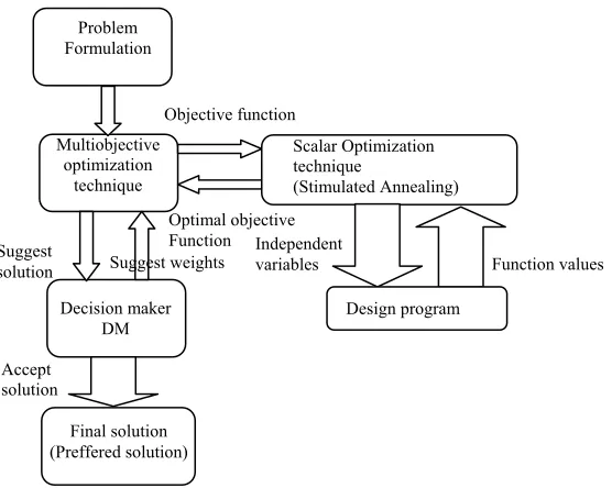
Fig. 1. Flowchart of multiobjective optimization of three phase self-excited induction generator Problem
Formulation
Multiobjective optimization
technique
Decision maker DM
Final solution (Preffered solution)
Scalar Optimization technique
(Stimulated Annealing)
Design program
Function values Optimal objective
Function Independent variables
Suggest weights Suggest
solution
Accept solution
Start
Read rating, set of independent variables (x1) and
constraints with bounds. Set initial temperature as t 0
Formulate the objective function
Calculate the value of objective function f1 = f(x1)
i = 1
Perform a cycle of random moves, each along one coordinate direction compute xi+ = xi + x, and calculate the value of
objective function (finew) also calculate f=finew-fi
Accept or reject each point using metropolis criterion
Is number of cycles >=nmax
Adjust step size, reset number of cycles to 0.
Is number of step adjustments>=nmax
Reduce temperature, reset number of adjustments to 0, set current point as optimum
Is temperature low? Yes Stop
Fig.2 Flowchart for optimization using SA technique No
No
Yes No
SIMULATEDANNEALINGTECHNIQUE
Simulated annealing is a combinatorial optimization technique based on random evaluation of the objective function in such a way that transition out of local optima are possible. Although the method usually requires a large number of function evaluations to find the optimum solution, it will find the global optimum with a high probability even for ill-conditioned functions with numerous local optima [39]. The simulated annealing method resembles the actual cooling process of molten metals through annealing [40]. The algorithm is as follows:
Step 1: Set initial temperature t=t1 and randomly choose an initial solution x.
Step 2: Generate a solution from the neighborhood of the current solution x. Let this solution be y
Step 3: If (f(y) >f(x))replace x by y, else replace x by y according to the Boltzmann criterion i.e., if exp (f(y) - f(x))/t < p replace x by y, where f(x) and f(y) are the values of the objective function for solutions x, y respectively; t, the temperature coefficient and p a random number uniformly distributed between 0 and I.
Step 4: Decrease the temperature.
Step 5: If stop criteria is met, then STOP. Else go to Step 2.
The stopping criteria is usually selected as a low temperature at which stage, no more improvement in the objective function value can be expected. The flowchart of SA algorithm is shown in Fig. 2.
3. IMPLEMENTATION OF SIMULATED ANNEALING TECHNIQUE TO MULTIOBJECTIVE OPTIMIZATIONOFINDUCTIONGENERATOR
The proposed approach is implemented for the optimal design of a sample induction machine [30] operating as induction generator whose ratings are given in appendix. In the case of a self-excited cage induction generator, the full load power factor, efficiency at unity power factor load and full load slip are different from those of induction motor, therefore, for the computation of these constraints the equivalent circuit of the machine and analytical technique [14] and [15] are considered. The machine parameters such as rotor and stator resistance, leakage and magnetizing reactance are computed at the design stage. The same method as stated in literature [14] is used to compute the capacitance required by machine at no load and full load. The performance indices such as voltage regulation, frequency regulation, efficiency, temperature rise, frill load power factor and full load slip are calculated as per technique used in [14].
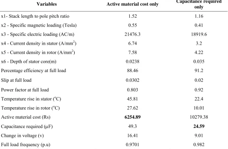
The constraints in optimization procedure are included by random search method [39]. The dimensions of the motor minimizing the two objectives (active material cost and capacitance required) separately using scalar optimization (SA) are shown in table I. By observing the variations in design parameters, it is evident that the geometry of the generator minimizing the material cost is not coincident with the geometry minimizing the capacitance required. The weighting multiobjective optimization technique is applied to optimize the design of the generator. The priorities of objective functions are represented by weights. Different weight values are given for each objective function. Table II gives different sets of Weights. The results of applying the multiobjective optimization approach to optimize the design of three phase self-excited induction generator are shown in table III.
4. RESULTSAND DISCUSSION
Variables Active material cost only Capacitance required only
x1- Stack length to pole pitch ratio 1.52 1.16
x2 - Specific magnetic loading (Tesla) 0.55 0.41
x3 - Specific electric loading (AC/m) 21476.3 18919.6
x4 - Current density in stator (A/mm2) 6.74 3.2
x5 - Current density in rotor (A/mm2) 7.58 4.22
x6 - Depth of stator core(m) 0.0238 0.035
Percentage efficiency at full load 88.46 91.2
Slip at full load 0.0302 0.02
Power factor at full load 0.803 0.92
Temperature rise in stator (oC) 45.81 22.4
Temperature rise in rotor (oC) 27.62 10.01
Active material cost (Rs) 6254.89 10279.38
Capacitance required (F) 49.3 24.59
Change in voltage (v) 16.41 9.01
Full load frequency (p.u) 0.9701 0.982
Generally the non-inferior solutions have the relation of tradeoff each other. The boundary values w1= 0 and w2= 1 give
the condition for minimum capacitance required, whereas W1=l and w2=0 give the condition of minimum active
material cost. When Wi is varied from 0 to 1 forcing w2 to vary from 1 to 0
Simultaneously, it is seen that the active material cost decreases continuously, but the capacitance required increases continuously. It is seen from the result of the algorithm explained in section 2, that the best compromise solution is determined when w is 0.533. Thus the active material cost has reduced from
Fig.3. Non inferior solutions
Rs. 7947.74 in the case of initial design to Rs 6752.9 and the capacitance required has reduced from
45.57
F to
35.8
F.
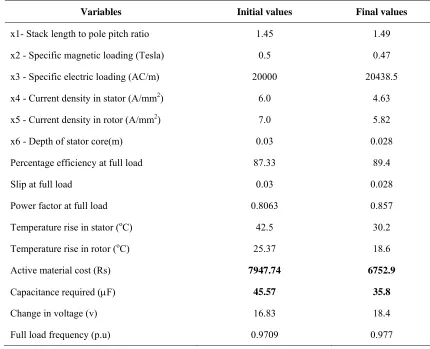
Table III shows the comparison between the initial model and optimized model.When the machine is designed with respect to minimizing both objective functions, the reduction in cost is about 15% of initial design. The capacitance required has also reduced by nearly 22%. The power factor and efficiency are improved than those obtained initially. Also the machine will have a better frequency regulation. However, the design of the machine comes out with poor voltage regulation. Hence a control device is necessary for voltage regulation.
The increase in power factor is due to the decrease of magnetizing current resulting from reduction in the value of air gap flux density. The increase in efficiency noticed is due to the large reduction in losses resulting from the redaction in the value of air gap flux density and stator current density moreover the reduction in losses will lead to a lower temperature rise.
W1 0.0 0.1 0.2 0.3 0.4 0.5 0.6 0.7 0.8 0.9 1.0
W2 1.0 0.9 0.8 0.7 0.6 0.5 0.4 0.3 0.2 0.1 0.0
TABLE III. COMPARISON OF INITIAL VALUES TO OPTIMAL VALUES ALGORITHM OBJECTIVE FUNCTION
Variables Initial values Final values
x1- Stack length to pole pitch ratio 1.45 1.49
x2 - Specific magnetic loading (Tesla) 0.5 0.47
x3 - Specific electric loading (AC/m) 20000 20438.5
x4 - Current density in stator (A/mm2) 6.0 4.63
x5 - Current density in rotor (A/mm2) 7.0 5.82
x6 - Depth of stator core(m) 0.03 0.028
Percentage efficiency at full load 87.33 89.4
Slip at full load 0.03 0.028
Power factor at full load 0.8063 0.857
Temperature rise in stator (oC) 42.5 30.2
Temperature rise in rotor (oC) 25.37 18.6
Active material cost (Rs) 7947.74 6752.9
Capacitance required (F) 45.57 35.8
Change in voltage (v) 16.83 18.4
Full load frequency (p.u) 0.9709 0.977
5. CONCLUSIONS
A package has been built and implemented to find the optimum design of a three phase sell-excited induction generator. These designs are achieved by defining a vector of independent variables and a vector of objective functions which should be minimized. The design problem is represented as a multiobjective optimization problem. The problem is solved by giving weights which reflect the priority of objective functions, and the Simulated Annealing technique is used as a tool to solve the problem. Through the results from the sample generator design, it is found that the proposed method is useful for multiobjective design of an induction generator. The obtained results are satisfactory and point out the effectiveness of a multiobjective approach since it allows us to find a good compromise among the proposed goals, and above all it represents an efficacious tool for the designer.
APPENDIX
Sample machine
ACKNOWLEDGMENT
The authors express their gratitude to the authorities of Annamalai University, Chidambaram, for permitting to do this work and for providing all the facilities.
6. REFERENCES
[1] T.F Chan, "Capacitance requirement of self excited induction generators", IEEE Trans. Energy Conversion, 8 (2), 1993, pp 304-311. [2] A L Alolah and M A Alkanhal, "Optimization-based steady state analysis of three-phase self-excited induction generator", IEEE Trans,
on 'ft Energy Conversion, 15(1), 2000, pp 61-65.
[3] E Suarez and G Bortolotto, "Voltage-frequency control of a self excited induction generator", IEEE Trans. Energy Conversion, 14 (3), 1999, pp 394 -401.
[4] A.K Al-Jabri, A.I. Alolah, "Capacitance requirements for isolated self-excited induction generator", IEEE Proc. 137 (Pt. B) (3), 1990, pp
154-159.
[5] S.S Murthy and B.Singh, "Capacitive VAR controller for induction generators for autonomous power generation", IEEE 96 International
Conference on Power Electronics, Drives and Energy Systems for Industrial Growth, India, vol. 95, 1996, pp. 679-686.
[6] J Arillage and D.B Watson. "Static power conversion from self excited
induction generator", proc IEEE, 10. 1978, pp 745-756.
[7] M.B Brennen and A.Abbondanti, "Static exciters for induction generators", IEEE Trans, on Industry Applications, 13, 1977, pp.
422-428.
[8] A.K Tandon, S.S Murthy and G.J Berg, "Steady state analysis of capacitor self-excited induction generator", IEEE Trans, on Power
Apparatus and Systems, PAS-103. 1983, pp 612-619.
[9] F.P Demello, J.W Feltes, L.N Hennett and F.C White, "Application of induction generators in power systems", IEEE Transactions on
Power apparatus and Systems, PAS-101, 1982, pp 3385-3993.
[10] S.S Murthy, OP Malik and A.K Tandon, "Analysis of self-excited induction generators" , Proc.IEE, 129: pt C: no 6, 1982, pp 260-265.
[11] A.K Al Jabri and A.I. Alohh, "Limits on the performance of three-phase self-excited induction generators", IEEE Trans, on Energy
Conversion, 5(2), 1990, pp 350-356.
[12] N.H Malik and A.H Al-Bahrani, "Influence of terminal capacitor on the performance characteristics of a self-excited indue ion generator",
IEE Proc. 137: ptC: 2, 1990, pp 168-173.
[13] S.S Murthy, B.P Singh, C Nagmani and K.V.V Satya Narayana, "Studies on the use of conventional induction motor as self-excited induction generators", IEEE Trans, on Energy Conversion, 3 (4), 1988, pp 842-848.
[14] S.P Singh. B Singh and MP Jain, "Performance characteristics and optimum utilization of induction generator", IEEE Trans, on Energy
Conversion. 5 (5), 1990, pp 679-685.
[15] S.P Singh, B Singh and MP Jain, "Steady state analysis of self-excited induction generator with ac-dc conversion scheme for small scale generation", Electric Power System Research, 2, 1991, pp 95-104.
[16] A.H Al-Bahrani and N.H Malik, " Steady state analysis and performance characteristics of three-phase induction generator self - excited with single capacitor", IEEE Trans, on Energy Conversion, 5 (4), 1990. pp 725-732.
[17] V.A Balagurov., A.A Ketsaris and A.N Ledovskii, "Optimal design of asynchronous generators for minimum weight",
Electrotekhnica 50(5), 1979, pp 37-40.
[18] ML Kostyrev, N.V Motovilov and A.A Druzhkov, "Algorithm fordesigning asynchronous generators with rectifier excitation for independent objects", Electrotekhnica, 57(7), 1986, pp 32-35.
[19] S.I Kitsis, "Features of the design and calculation of submersible asynchronous self-excited generators", Electrotekhnica, 57(11) 1986, pp. 36-37.
[20] S.S Murthy, H.S. Nagaraj and A. Kuriyan, "Design-based computational procedure for performance prediction and analysis, of self-excited induction generators using motor design package" IEE Proc., 135, Pt. B, No. 1, 1988, pp 8-16.
[21] J Faiz. A.A Dadgari. S Horning and A.Keyhani. "Design of three phase self-excited induction generator", IEEE Trans, on Energy
Conversion, 10 (3), 1990, pp 516-523.
[22] Wang Li and Ching-Huei Lee, "A novel analysis on the performance of an isolated self-excited induction generator", IEEE Transactions on
Energy Conversion 12(2), 1997, pp 109-117,
[23] C.Chakraborty S.N Bhadra and Ajit K. Chattopadhyay, "Excitation requirements for standalone three-phase induction generator", IEEE
Transactions on Energy Conversion, 13(4), 1998, pp 358-365.
[24] R. J Harrington and F.M.M Bassiouny, "New approach to determine the critical capacitance for self-excited induction generator", IEEE
Transactions on Energy Conversion, 13(3), 1998, pp 244-249.
[25] T. F Chan, and Loi Lei Lai, "Capacitance requirements of a three phase induction generator self-excited with a single capacitance and supplying a single-phase load", IEEE Trans, on Energy Conversion, 17(1), 2002, pp 90-94.
[26] S.P Singh, B Singh and M.P. Jain, "Comparative study on the performance of a commercially designed induction generator with induction motors operating as self excited induction generator", IEE Proc, pt C, 140(5), 1993, pp 374-380.
[27] T.F. Chan, "Analysis of self-excited induction generators using an iterative method", IEEE Transactions on Energy Conversion, 10(3), 1995. pp 503-507.
[28] T F Chan, “Performance Analysis of a three-phase induction generator self- excited with a single capacitance", IEEE Transactions on
Energy Conversion, 14(4), 1999, pp 894-900.
[29] R.Kannan, R.Bhuvaneswari, S.Subramanian, “Optimal design of three phase induction motor using particle swarm optimization”, Iranian Journal of Electrical and Computer Engineering, 2007, vol: 6, no: 2, PP 105-111.
[30] R.Kannan, R.Bhuvaneswari, S.Subramanian, “Optimal design of three phase induction generator using CLONAL selection algorithm”, International Journal of Electronic and Electrical Engineering, 2009, vol: 6, no: 4, PP 36-47.
[31] S.P Singh, Sanjay K Jain and J.Sharma, Voltage regulation optimization of compensated self-excited induction generator with dynamic load", IEEE Trans. on Energy Conversion, 9(4), 2004, pp 724- 732.
[32] S.P Singh, B Singh and M.P. Jain, "Optimization of self-excited cage induction generator design", Journal of Institute of Engineers (Electrical) India,76, 1995, pp 18-22.
[33] S. Kirkpatrick, CD Gelatt, and M.P.Vecchi, "Optimization by simulated annealing". Science, Vol 220, no 4598, 1983. pp
671-680.
[34] S.Subramanian and R.Bhuvaneswari, "Optimization of three phase induction motor design using simulated annealing algorithm", Electric
Power Components and Systems, vol 32, no 9, 2005.
[35] S.Subramanian and R.Bhuvaneswari, "Multiobjective optimal design of three-phase induction motor using simulated annealing technique",
The International Journal for Computation and Mathematics in Electrical Engineering, vol 24(4), 2005.
[36] H.V Kalankesh, Sharifian and M.R. Feyzi, "Multiobjective optimization of induction motor slot design using finite element method1”,
Proceedings of Australian Universities Power Engineering Conference-AUPEC 2003, Christchurch, New Zealand, 2003.
[37] MX Kim, C.G Lee and H.K Jung, "Multi objective optimal design of three phase induction motor using improved evolution strategy", IEEE
Transactions on Magnetics, 34(5), 1998, pp 2980-2983.
[38] A. Osyczka, Multicriterion Optimization in Engineering with FORTRAN Programs, Ellis Howard Limited, England, 1984.
[39] S.S. Rao, Engineering Optimization - Theory and Practice, New Age International (P) Ltd, New Delhi, Third Edition, 1996, pp 811-814.
[40] K Deb, Optimization for Engineering Design, PHI Pvt. Ltd, New, Delhi, 1998.pp 320-325.
About the authors
R.Kannan is working as a Senior Lecturer in the Department of Electrical Engineering, Annamalai
University. He received his BE (Electrical) (2000) degree and ME (power system) (2005) degree from Annamalai University. He is doing PhD work in design analysis of electrical machines.
R.Kannan is the corresponding author and can be contacted at: [email protected]
S.Subramanian is working as a Professor in the Department of Electrical Engineering, Annamalai
University. He received his BE (Electrical) and ME (power system) (distinction) degree in the year 1989 and 1990 from Madurai Kamaraj University. He received his PhD in the area of power system economics during the year 2001 from Annamalai University. He has guided 20 BE projects, 20 ME projects and 5 PhD projects. He is guiding seven students towards PhD program. He visited Singapore and Malaysia for technical paper presentation. He published 80 research articles in various referred international journals, national journals, international conferences and national conferences. He is review committee member for various journals. He acted as a Chair Person for various national level conferences. He is a member in Institution of Engineers, System Society of India, and India Society for Technical Education and Indian Science Congress Association. He is a doctoral committee member for various universities. His area of interest includes power system operation and control, design analysis of electrical machines, power system state estimation and power system voltage stability studies. His biography has been included in MARQUIS who is who in the world, MARQUIS who is who in Engineering and International Biographical Centre (IBC) UK. [email protected]. He is a Senior Member IEEE.
R.Bhuvaneswari is working as an Assistant professor in the Department of Electrical Engineering,