Volume-6 Issue-1
International Journal of Intellectual Advancements and
Research in Engineering Computations
Boiler fans protections and interlocks using
microcontroller in 210mw MTPS
V.Parameshwari
1, S.Raghul
2, K.Sanjay
3, K.S.Sarika
4, S.Santhosh
5,
1Assistant professor, Department of Electronics and Communication Engineering,
2345UG students, Department of Electronics and Communication Engineering,
Nandha Engineering College(Autonomous), Erode-52, Tamil Nadu, India.
1
[email protected],
2
[email protected],
3[email protected],
4[email protected],
5
[email protected]
Abstract— The proposed system is an attempt to find out the boiler fan damages and failures that takes place during the operating process. The boiler fans are mainly used to maintain the pressure inside the boiler to make combustion process efficient. In order to protect boiler draft fans there are certain temperature limits allocated to the motor and fans of the boiler. If it exceed the allocated value automatically the motor gets tripped. To protect the boiler fans there is a need to perform interlocking mechanism. Whenever there is a damage in any one of the three boiler fans such as PA fan, ID fan and FD fan immediately the remaining fans are shutdown using interlocking mechanism.
Index Terms—boiler fans, motors, temperature, interlocking, monitoring and functioning.
I.INTRODUCTION
The purpose of boiler in thermal power plants is to covert water into steam with the help of heat energy generated by the combustion of fuels like coal, wood, oil or natural gas. There are many types of boilers developed in order to meet variety of duties. Boiler systems use several types of fans to maintain air flow, recirculate air and remove exhaust gases. Based on the boiler size and air flow requirement different fans are used with varied capabilities. Predominantly, draft fans play an important role in thermal power plants because they regulate the air pressure inside boiler system. Draft fans are broadly divided into two types – Forced Draft (FD Fan) and Induced Draft (ID Fan). Apart from the draft fans, there are also other
basic types of process fans used in power plants. They are primary air fans and flue gas recirculation fans. Draft Fans. The primary difference between a forced draft and induced draft is, FD fan forces outside air into the heating system whereas ID fan draws flue gases from the system out into the atmosphere. Both FD fan & ID fan operate in such a way that it balances the air system in the boiler to make the combustion process efficient.
II.LITERATURE SURVEY
1. Development and Application of boiler combustion air Flow control algorithm for coal-fired power plant
This paper is written for developing combustion air control algorithm of coal-fired power plant by the steps of design, coding, tests to power plant. The control algorithm was coded to the control programs of distributed control systems
2.
The research on the draught fan system of the power plant boiler based on fuzzy adaptive PID control3.
Control Strategy for Main Steam Pressure of Combustion System of Pulverized Coal BoilerIn this paper, a well-performed coal-fed plan is spresented for the direct blow pulverized coal-fired boiler according to the conditions of fan mills. The main steam pressure can be controlled.
4
.
Energy Saving in Electric Drive of Boiler Blow FanThis paper is to calculate instantaneous values of power components that are consumed from power source. It reduces the power consumption.
5.
Research on Stability Criterion of Furnace Flame Combustion Based on Image ProcessingThe paper proposes and analyzes the stability criterion of furnace flame combustion. Furnace flame combustion is stable.
III.PROPOSED SYSTEM
The purpose of the boiler fan protection and interlocks is to bring the boiler at an ideal temperature by making combustion process efficient and preventing the damages and failures of fans by performing interlocking mechanism using microcontroller.
A.BLOCK DIAGRAM
Figure III. A. Block diagram of boiler fan protection and interlocks.
Description
The parameters such as motor bearing DR/NDR temperature , motor winding temperature , fan bearing DR/NDR, initial conditions, trip conditions and indications unit are taken here. Logic switches are used for initial and trip conditions. In this system arduino mega 2560 microcontroller For real time value monitoring we have used LCD display. Optocoupler is used to trip 230V motor. Temperature sensor is the major source of our project. Temperature sensor unit and logic switches are coupled in arduino. The output is given to LCD, LED and Optocoupler to obtain the result.
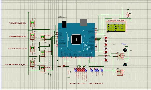
B.CIRCUIT DIAGRAM
Figure III.B.Circuit diagram of boiler fan protection and interlocks
Description
The circuit diagram consist of one arduino mega 2560, 7 temperature sensors( LM35), 16x2 LCD display, 2 optocouplers, 2 motors, 5 led’s and 10 logic switches. In this logic switch is used to check the status and startup conditions of the boiler fans.LED lights are used to indicate the trip level. Temperature sensors are used to detect the boiler fan temperature. The temperature is given as the input to the microcontroller. The optocoupler is used for the switching between the motors.LCD is used to display the real time values of the temperature of the boiler fans.
bearing drivable end temperature-very high, u4 is used to detect the motor bearing non drivable end temperature-very high, u5 is used to detect the fan bearing drivable end temperature-high, u6 is used to detect the fan bearing non- drivable end temperature-high, u7 is used to detect the motor winding temperature.
There are two conditions for logic switches. They are initial and trip conditions.The1st switch in initial conditions is used for checking the FDF-A-FAN, the 2nd switch is for CNTL-STATUS MAN, 3rdswitch is for NO-TRIP-COND, 4th switch is for TD/FD OPTR PERMIT.5th switch is for FDF-A-VANE MIN POS, 6thswitch is for FDF-A-DISCH-DMPR-CLSD. The 1stswitch in trip conditions is used for checking ID-A-RUN, 2ndswitch is A-ID-A-RUN, 3rd switch is for FD-A-STOP, 4th switch is for ID-STOP.
The LED light is used to indicate when the temperature exceeds the limits.LCD display the real time values for the boiler fan temperature. Optocoupler acts as a switch to trip the motors.
Operating Procedure
Transformer 12V AC supply is connected to the circuit.
Step-1
Switch ON the Transformer primary supply (230V AC). The LCD displays the project parameters like boiler fans temperature, motor bearing temperature, initial startup conditions and trip conditions.
Step-2
The logic switches for initial conditions are used to check the permissions and indicate whether the system is ready or not to proceed further operation.
Step-3
The temperature sensors give the real time value of boiler fan and motor temperature. LED are used to indicate whether the temperature exceeds the certain limits.
Step-4
If the temperature are very high and above the limit then the optocouplers are used to trip the motors.
Step-5
For manual trip of motors separate switches are given. So the manual trip operation are performed.
C.DETAILS OF HARDWARE
BOILER FANS:
ID FANS
ID fan is basically mentioned here for Induced draft fan and ID fan is always located between dust collector and chimney. ID fan will take the hot flue gases from furnace via dust collector (dust separation system or Fume Extraction system) and will deliver to chimney. ID fan will handle the flue gases i.e. hot air.
ID fan will produce the pressure lower than the atmospheric pressure in the system or we may say that ID fan will produce the negative pressure in the furnace to remove the flue gases from furnace via electrostatic precipitators and to push the flue gases to chimney.
FD FANS
FD fan, which is mentioned here for forced draft fan, is used basically for providing the required quantity of hot air to the furnace for smooth and uniform combustion of fuel. FD fan will produce the positive pressure inside the system i.e. furnace.
PROTEUS SOFTWARE
PROTEUS
Proteus is software for microprocessor simulation, schematic capture, and printed circuit board (PCB) design. It is developed by Labcenter Electronics. PROTUES combines advanced schematic capture, mixed mode SPICE simulation, PCB layout and auto routing to make a complete electronic design system. The PROTUES product range also includes our revolutionary VSM technology, which allows you to simulate micro-controller based design, complete with all the surrounding electronic.
PROTEUS FEATURES
ISIS Schematic Capture an easy to use yet and extremely powerful tool.
PROSPICE Mixed mode SPICE
Simulation industry standard SPICE3F5 simulator upgradeable to our unique virtual system modeling technology.
ARES PCB Layout.
Modern Graphical User Interface standardized across all modules.
Technical Support direct form the author.
Rated best overall products.
SYSTEM COMPONENTS
ISIS Schematic Capture - a tool for entering designs.
PROSPICE Mixed mode SPICE simulation - industry standard SPICE3F5 simulator combined with a digital simulator.
ARES PCB Layout - PCB design system with automatic component placer, rip-up and retry auto-router and interactive design rule checking.
VSM - Virtual System Modelling lets simulate embedded software for popular micro-controllers alongside hardware design.
System Benefits Integrated package with common user interface and fully context sensitive help.
Proteus is an ambitious approach with a potential to touch many aspects of healthcare. Several prototype software tools developed have validated the core features
ARDUINO
The Arduino Mega 2560 is a microcontroller board based on the ATmega2560. It has 54 digital input/output pins (of which 15 can be used as PWM outputs), 16 analog inputs, 4 UARTs (hardware serial ports), a 16 MHz crystal oscillator, a USB connection, a power jack, an ICSP header, and a reset button. It contains everything needed to support the microcontroller; simply connect it to a computer with a USB cable or power it with an AC-to-DC adapter or battery to get started.The Mega 2560 board is compatible with most shields designed forthe UNO
IV.RESULTS AND DISCUSSIONS
1. SIMULATION RESULT
Figure IV.1 simulation output
The following results are observed from this
Quick response where the time taken to process is very low
Automatic shutdown of the fans are easily initiated
Handling of the proposed system is simple and effective
Easy to analyze and simulate the parameters.
V. MERITS & DEMERITS A. MERITS
Easy to monitor the bearing temperature of both fans and motor.
Can be easy to identify the defective or high temperature of any bearing or winding of motor.
Motors RPM can be linearly controlled.
To minimize the blow down of Boiler fan.
B.DEMERITS
Only one divisions of both the fans are performed.
This system is not applicable for entire fans operation
This system is difficult to operate under industrial conditions
VI. CONCLUSION
down. In the proposed system interlocking mechanism must be performed, so that if one fan gets damaged , the remaining fans will be forced to shut down. Now it is easy to figure out and eliminate the damages in fans and the replacement of fan is avoided.
VII. REFERENCES
[1] Geon Pyo Lim, Green energy laboratory KEPCO Research Institute Dae-jeon City, Republic of Korea ,Heung-Ho Lee,Department of electrical engineering Chung-Nam university Dae-jeon City, Republic of Korea“Development and Application of boiler combustion air Flow control algorithm for coal-fired power plant”, IEEE 8th Conference on Industrial Electronics and Applications(ICIEA),pp 662-667,2013.
[2] RongPanxiang, Li Chao and Han Leng School of Automation, Harbin University of Science and Technology, Harbin China,”The research on the draught fan system of the power plant boiler based on fuzzy adaptive PID control”,The 6th International Forum on Strategic Technology,pp 979-982,2011.
[3] Jinjie Huang, Guangming Cheng, Xiaolin Chi, Yujie Zhang, Department of Automation Harbin University of Science and Technology Harbin, China,”Control Strategy for Main Steam Pressure of Combustion System of Pulverized Coal Boiler”,Intemational Conference on Measurement, Information and Control (MIC),pp 805-808,2012.
[4] Ivan Georgievich Slepnev , Igor Aleksandrovich Chernyshev , Alexander Yurievich Chernyshyov , National Research Tomsk Polytechnic University TPU Tomsk , Russia , ”Energy Saving in Electric Drive of Boiler Blow Fan”, 2017.
[5] Rongbao Chen , Wuting Fan , Jingci Bian , Fanhui Meng , Institute of Electrical Engineering and Automation Hefei University of Technology Hefei , China , ”Research on Stability Criterion of Furnace Flame Combustion Based on Image Processing”, International Conference on Control Engineering and Communication Technology,pp568-572,2012.
[6] ZhuoXu-sheng噛 , Yang Fan , Qin Shi-hong , Zheng Sheng School of Electrical and Information Engineering , Wuhan Institute of Technology, Wuhan 430073, Hubei Province, China .Series Cascade Control of Coal-Fired Drum Boiler, 2011.
[7] Chen Hai-ping , Wang Bing-li , Shi Wei-zhu , MaQiang , TanChao , Fanzhi-qiang Department of Thermal Engineering North China Electric Power University Baoding , 071003 ,Description of Exergy Transfer in the Power Plant Boiler’s Heat Transfer Process , 2009
[8] Rongbao ChenWuting FanJingci Bian Fanhui Meng Institute of Electrical Engineering and Automation Hefei University of Technology Hefei , China Research on Stability Criterion of Furnace Flame Combustion Based on Image Processing , 2012.
[9] Jeffery Isper , The Application of Adjustable-Frequency Controllers to Forced-Draft Fans for Improved Reliability and Energy Savings , 1988.
[10] Aipeng Jiang 1, Weiwei Lin1, Qiang Ding1, Zhifeng Liu2, Jiafeng Fan2, Shao Bing1 1) School of automation, Hangzhou Dianzi University, Hangzhou, 310018 (E-mail: [email protected]) 2) ZouchengBoda Electric Power Automation Engineering Co., Ltd. Zoucheng, 273500, Shandong, China,Research on combustion control and heat efficiency’s online computing of slime fluidized bed boiler,2012.
[11] Mr. Rajashekar P. Mandi and Dr. S. Seetharamu Energy Conservation & Development Division, Central Power Research Institute, Bangalore, India, Dr. Udaykumar R. Yaragatti Dept. of Electrical & Electronic Engineeri National Institute of Technology, Surathkal, India,Enhancing energy efficiency of auxiliary power system in a 210 MW coal fired power plant through energy efficiency ,2010.
[12] Jeffery D. Rozner, Paul W. Myers, member, IEEE, and Carl J. Robb, Associate,The Application of Adjustable Frequency Controllers to Forced Draft Fans for Improved Reliability and Energy Savings,1985.