Volume-7 Issue-1
International Journal of Intellectual Advancements
and Research in Engineering Computations
An embedded based electric shock prevention system using IOT
S.R.Manthra Laxmi
1, C.Ruban Surya
1, A.Samsudhin
1, V.Sandhiya
1, Mrs.S.Nandhini
2 1UG Students, Department of ECE, Department of ECE, Nandha Engineering College (Autonomous),
Erode-52, Tamil Nadu
2
Assisstant Professor, Department of ECE, Nandha Engineering College (Autonomous), Erode-52, Tamil
Nadu
ABSTRACT
A electric shock is of both magnitude and duration of touch voltages that preeminent to protect persons against electric shock hazards, such as those caused by basic insulation failure in equipment/appliances, or direct contact with live parts. The paper considers the effect of the composite waveforms on the threshold of ventricular fibrillation. The new idea, intelligent system of electrical safety enables for selective disconnection of supply only when the real hazard of fibrillation occurs. In this system, as soon as the high current is detected, the system gets tripped before the load gets grounded. The detected shock will be sent to the cloud by using IOT for further prevention. By using this intelligent system both the effective protection against electric shock and high reliability of supply are achieved.
INTRODUCTION
A device providing for discharging static electricity between a person and a grounded object to prevent un pleasant static shock to the person includes an insulated housing supporting a first contact arranged for manual engagement, a second contact for contacting the grounded object and a conductor of high resistance there between for allowing transmission of current at a rate which is sufficiently low to avoid shock. An electric shock preventer provides electrical shock protection for human, which consist of shock sensing element and transceiver module. This electric effect can lead to even death.
A current sensing circuit includes a power transistor, a sensing transistor configured to copy a current flowing through the power transistor at a predetermined ratio, a current sensing resistor configured to detect a voltage from the current copied by the sensing transistor, an input resistor
a cross self- biasing cascade block configured to adjust currents at both ends of the input resistor, and a common gate transistor and a reference resistor configured to convert a current output of the input resistor to a final sense voltage.
The fundamental rule of protection against electric shock is that hazardous live parts must not be accessible, and accessible conductive parts must not be hazardous live, neither under normal conditions nor under single fault conditions. Protection under normal condition is provided by basic protective provisions (protection against the direct contact in the fourth edition), and protection under single fault conditions is provided by fault protective provisions (protection against the indirect contact). The following protective measures are generally permitted: protection by automatic disconnection of supply, double or reinforced insulation, electrical separation, and extra low voltage (safety extra low voltage and protective extra low voltage) [1-5].
methods for detection of unsafe electrical conditions with respect to the grounding of electrically operated mining equipment. It also includes a discussion of prototype instruments which effectively monitor the condition of the grounding safety devices currently in use on
conditions as soon as they appear.The objective of the system is to describe methods for detection of unsafe electrical conditions with respect to the grounding of electrically operated mining equipment.
PROPOSED METHOD
In Existing system, the Miniature circuit Breaker will trip off the whole circuit if any leakage occurs irrespective of current rating. But in the proposed method, the range of voltage passing through the conductor is measured through potential sensor and the circuit will compare the value using comparator and will send the information to the receiver.
According to the rate of voltage passed to the conductor, the microcontroller will pass the information and the relay will trip off the circuit. The place where the accident happens will be traced through GPS and the information will be uploaded to the server using IOT. The main advantage of the proposed method towards the existing system is the tripping time which is less than 30milliseconds.
BLOCK DIADRAM
Transmitter block
Figure.1Transmitter
CIRCUIT AND CONNECTION
The PIC microcontroller is made to connect with the comparator which is accordingly made in contact with a potential sensor which can measure the voltage that received in a human body. The zigbee module is made contact with the 16f877a microcontroller to send the information to trip off the current. The potential sensor is already in contact with the human body and checks whether the current passing is getting high, if it gets high
Receiver block
Figure.2 Receiver
WORKING PLAN
Potential sensor:
Potential sensor is a combination of resistor and capacitor that detects the current and analysis the current variation. The resistor resists the current flow and capacitor loads the current slowly. It senses the voltage in the human body and compares with the external current flow. The current flow over flows then the signal passed to comparator.
Comparator
The comparator compares one analogue voltage level with another analogue voltage level, or some preset reference voltage, VREF and produces an
output signal based on this voltage comparison. In other words, the op-amp voltage comparator compares the magnitudes of two voltage inputs and determines which is the largest of the two. The preset value exceeds then the signal sent to the controller in [A].
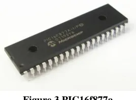
Pic microcontroller
PIC is a Peripheral Interface Microcontroller which was developed in the year 1993 by the General Instruments Microcontrollers. It is controlled by software and programmed in such a way that it performs different tasks and controls a generation line. PIC microcontrollers are used in different new applications such as smart phones, audio accessories and advanced medical
The PIC microcontroller PIC16f877a is one of the most renowned microcontrollers in the industry. This controller is very convenient to use, the coding or programming of this controller is also easier. One of the main advantages is that it
because it uses FLASH memory technology. It has a total number of 40 pins and there are 33 pins for input and output. PIC16F877A is used in many pic microcontroller projects. PIC16F877A also have many applications in digital electronics circuits.
Figure.3 PIC16f877a
PIC16f877a finds its applications in a huge number of devices. An EEPROM is also featured in it which makes it possible to store some of the information permanently like transmitter codes and receiver frequencies and some other related data. The cost of this controller is low and its handling is also easy. It is flexible and can be used in areas where microcontrollers have never been used before as in coprocessor applications and timer functions etc.
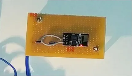
Zigbee module
The zigbee module connected with the PIC16F877A controller when the high current is detected. Zigbee module gets the signal and then it transmits to the receiver module. The receiver module detects the signal from the transmitter module and the controller on receiver side detects that high voltage and current is passing in a human body. The controller gets the signal and passes it to the relay driver.
Figure. 4 Zigbee Module
Relay driver
The relay receives the signal from the controller and trips the current and voltage flow from electricity board. Relays which allow a low-power circuit to switch a relatively high current on
Figure. 5 Relay Driver
IOT module
IoTmodule which is kind of built-in-sensors with the ability to collect and transfer data over a network without manual intervention. The signal
sent from the controller which helps in decisions making process of sending the data to the cloud to save the data.
Figure. 6 IOT Module
DRAWBACKS OF EXISTING
METHODS
Expense
While inexpensive options exist, low-cost MCBs offer limited protection against short circuits. Applications where short circuits currents may exceed 1,000 amps require more expensive breakers. Miniature circuit breakers that protect above 1,000 amps tend to cost more than other types of circuit breakers.
Vulnerability to Heat
Miniature circuit breakers show high susceptibility to changes in temperature within
their operating environment. As temperature rises in the surrounding environment or via heat from electrical current, it affects the bending of the metal strip within, [6, 7] diminishing the breaker's current capacity. Miniature circuit breakers designed to compensate somewhat for this disadvantage can reduce the effects that temperature changes have, but this boosts the cost of the already-expensive MCB.
Slow Tripping
current. Type D breakers react to surges of 10 to 20 times the normal load. Type B miniature circuit breakers react more quickly, between three and 4.5 times the normal full load current, but only prove useful in environments with little risk of surges, such as in incandescent lighting circuits.
Aging and Wear
The metal strips within miniature circuit breakers wear as they age, and this may cause the breaker's reaction time to slow. This delay will diminish the breaker's ability to trip in a timely
electronics to damage from surges and overloads.
Advantage of proposed system
Workers in building construction can use this application where as they will be using driller machine and more electrical appliances for construction.
It can be used in automobile industries.
It helps the people who works in the industries, where they use more electricity and more electrical equipments.
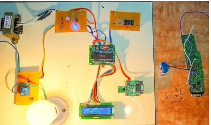
OUTPUT
Figure .7 Output
CONCLUSION
The protection practice against electric shock points to solve the contact “collision” by the active measure of automatic disconnection limiting the time duration. Analyzing the components of electric hazard as waves evolving in time, the fault opens a time window of risk, and the protection has to close it. In electrical installations, safe protection is conventionally guaranteed if the colliding time makes permissible the prospected touch voltage or at least assumes a value as low as possible (additional protection). In fact, as a
minimal objective, the protection has to limit fault exposure persistence in a conventional time (probable protection).
In this proposed system, the electric shock is completely prevented by tripping off the circuit before the human body get affected by the electric shock. The information about the hazard is uploaded to the cloud through IOT which helps in preventing the further hazards that can be managed by the admin. In future, this system can be implemented over the industries where the electric hazard rate is large.
REFERENCES
[1]. M.Mitolo and T.J.Bajzek., “Measuring the Electrical Safety in Low-voltage Distribution Systems”, IEEE Transactions on Industry Applications, 2018.
[3]. Stanislaw Crzapp and DariuszSwisulski., “Lab VIEW-based Intelligent System Of Protection against Electric Shock for Photovoltaic Installations”, IEEE Transactions on Education, 2017.
[4]. Lloyd B.Gordon, Laura Cartelli and Nicole Graham, “A Complete Electrical Shock Hazard Clasification System and its Applications”, IEEE Transactions on Industry Applications, 2016.
[5]. DaleepMohla, Craig M.Wellman and Kevin J.Lippert, “Prevention Through Design: Reducing Risks Near service and main disconnects”, IEEE Transactions on Industry Applications, 2015.
[6]. Trevor W. Dawson, KrysCaputa, Maria A. Stuchly, and R. Kavet, “Electric Fields in the Human Body Resulting From 60-Hz Contact Currents”, IEEE Transactions of Biomedical Engineering, 48(9), 2001.