Vincent et al. World Journal of Engineering Research and Technology
PERFORMANCE ANALYSIS OF A 1.5 KW PHOTOVOLTAIC POWER
SYSTEM
Vincent N. Ogar*1, Sampson A. Bendor2 and Akpama E. James3
1
Department of Electrical/Electronic Engineering, Cross River University of Technology,
Nigeria.
2
Department of Electrical/Electronic Engineering, Cross River University of Technology,
Nigeria.
3
Department of Electrical/Electronic Engineering, Cross River University of Technology,
Nigeria.
Article Received on 09/06/2017 Article Revised on 29/06/2017 Article Accepted on 20/07/2017
ABSTRACT
Due to the rising fuel costs resulting from the deregulation of the
downstream oil sector in Nigeria, increasing concerns for global
climatic change, and a growing worldwide demand for electricity,
utilizing renewable energy sources such as solar power becomes a
necessity rather than a luxury. Despite the large quantity of energy
absorbed by the earth from the sun yearly, only a fraction of that is
captured for electrical power production. Solar powered systems can generate electricity
using photovoltaic (PV) panels. PV systems can range from utility scale systems (about
14MW) solar arrays 4KW roof-top home systems to small wattage solar backpack for
charging portable electronics. This project explores solar PV systems for residential
buildings, using three offices as a case study. The design and implementation was based on
1.5KW inverter with two 200Ah deep cycle batteries, 20Amp charge regulator and four
80Watts solar panels.
KEYWORDS: Photovoltaic Cell, Charge Controller, Inverter, Battery, Load and Energy Demand.
*Corresponding Author Vincent N. Ogar
Department of
Electrical/Electronic
Engineering, Cross River
University of Technology,
Nigeria.
World Journal of Engineering Research and Technology
WJERT
INTRODUCTION
Sunlight is made up of tiny packets called photons.[1] Every hour enough of this energy reaches the world to meet the world's energy demand for the whole world. Photovoltaic
panels consists of many solar cells, these are made of materials like silicon, one of the most
common elements on earth. The individual cell is designed with a positive and a negative
layer to create an electric field, just like in a battery. As photons are absorbed in the cell, their
energy causes electrons to become free, the electrons move toward the bottom of the cell, and
exit through the connecting wire. The flow of photons is what we call electricity. By
combining solar cells and photovoltaic panels, we can produce just the right amount of
electricity to perform a specific job, no matter how large or small.[2]
Solar energy is the energy derived from the sun through the form of solar radiation.[3] Solar technologies are broadly characterized as either passive solar or active solar depending on the
way they capture, convert and distribute solar energy. Photovoltaic is a combination of two words “Photo” from Greek root meaning, light and “Voltaic” from volt which is the unit used
to measure Electric potentials at a given point.[2] Solar technologies tap directly into the power of the sun to produce solar energy which is converted into solar electricity using
Photovoltaic (PV) Cell technology.[1] Active solar techniques include the use of photovoltaic panels and solar thermal collectors to harness the energy. Passive solar techniques include
orienting a building to the Sun, selecting materials with favorable thermal mass or light
dispersing properties, and designing spaces that naturally circulate air. Photovoltaic (PV)
cells convert sunlight directly to electricity. They work any time the sun is shining, but more
electricity is produced when the sunlight is very strong and strikes the PV cells directly. The
basic building block of PV technology is the solar cell. Solar power in rural areas is a viable
alternative for providing electricity for telecommunications, telemetry, water pumping,
lighting, television, DC refrigeration and other low power non- heating applications. Heating
appliances such as kettles, toasters, stoves, geysers and heaters are consuming too much
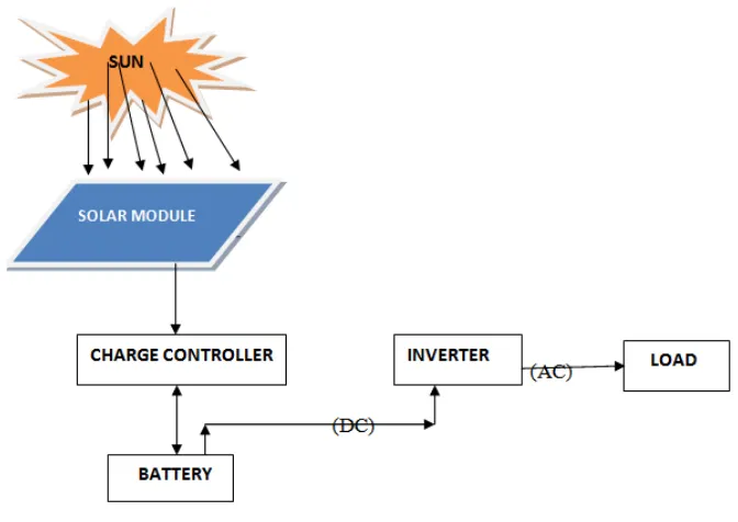
energy and therefore cannot be used on a solar system.[4] The basic components for this solar energy system are; solar cell, solar panel, inverter, battery, charge controller, wiring, and connected loads. The photovoltaic modules normally have a manufacturer’s power output
warrantee of 20 to 25 years. The only maintenance on a solar module is to clean the glass on
a regular base. The regulator has a 1 year warrantee, but can be damaged if the instructions
expected lifetime is between 3-4 years. Most of the solar batteries available are semi sealed
batteries and are low maintenance or maintenance Structural features.
Fig. 1.0: Block diagram of the system.
2.0REVIEW OF RENEWABLE ENERGY
Renewable energy is energy which comes from natural resources such as sunlight, wind, rain,
tides, and geothermal heat, which are renewable (naturally replenished).[5] Renewable energy is derived from natural processes that are replenished constantly.[4] In its various forms, it derives directly from the sun, or from heat generated deep within the earth. Included in the
definition is electricity and heat generated from solar, wind, ocean, hydropower, biomass,
geothermal resources, and biofuels and hydrogen derived from renewable resources.[5] Renewable energy is a form of energy that can be produced without depleting natural
resources such has fossil fuels and wood. It does not rely on the burning of a fossil fuel to
create electricity. This type of energy is sustainable as it is derived from sources that do not
run out. Renewable energy is that form energy obtained from sources that are essentially
inexhaustible, unlimited and rapidly replenished or naturally renewable such as wind, water,
sun, wave, refuse, biofuels etc.[6] It has brought about the need for technology innovation as a means to addressing climate change challenges that is, by reducing the rate and volume of
green house gases (GHGs) emissions/concentration in the atmosphere and saves the ozone
layer from on-going depletion, which eventual collapse would spell catastrophe to the world.
skilled manpower, especially in the developing nations where technology advancement is a
desideratum.[5] Renewable energy has the following advantages.[5]
It is highly sustainable as it is derived from sources that are inexhaustible. It does not emit
any greenhouse gases or toxic waste making the world a cleaner and safer place. It is highly
cost effective as fuel does not need to be brought to sustain the electricity plant. It is also cost
effective as less labor is needed to operate a renewable energy station and they require less
maintenance. They may bring economical benefits to remote communities, as many
renewable energy plants are situated away from large cities.
Renewable energy generators such as solar power can be applied to existing buildings
making them more environmentally friendly and energy efficient. Some forms of renewable
energy such as geothermal steam plants take up less area than larger conventional power
plants and can be run day and night.
Hydroelectric power stations can be controlled to produce more power at peak times and be
inactive during lulls in power usage. Biomass energy helps cut down on the amount of
rubbish that is transported to landfills. In most cases if an individual has a renewable energy
source, such as solar power, attached to their home or business they can sell any excess
power back to the grid reduce the overall amount of homes or businesses being powered by
fossil fuel plants. Renewable energy replaces conventional fuels in four distinct areas: power
generation, hot water/ space heating, transport fuels, and rural (off-grid) energy services.[5]
Procedure for Result presentation
To effectively design the photovoltaic system, certain factors were considered. These factors
include.
(a) Total load and energy demand.
The total load and energy demand enable us to determine the capacity or sizes of the
following equipments:
ii Size of the inverter.
ii Size of battery bank.
iii Size of the solar panel.
iv Size of the charge controller.
3.0 Determination of total load and energy demand
There are four issues that arose in the design of the system.
That the load on the system is not constant over the period of the day.
The daily load varies over the year.
The energy available from the sun source may vary from time to time during the day.
The available energy radiant from the sun source varies from day to day during the year.
If the system is based on photovoltaic module, that a comparison should be made between.
The actual energy demand and the available energy from the sun.
In all cases, the first step in system sizing is to estimate the load placed on the system and to
examine the actual requirements from the system.
This is done by establishing an AC and DC load assessment sheets. But since the project is
aimed at the use of AC, the AC load assessment shall be considered.
Load Assessment Procedure
It is imperative that the assessment process captures the following,
PRPA * N = TPRPA (Watts)………..1
Where PRPA is Power Rating per Appliance.
N is Number of each appliance to be powered.
NOTE: N is not constant.
TPRPA * T = E (Whr)……….2
Where E is Energy in Watt-hour (Whr).
TPRPA is the total power rating per appliance
T is back-up hour.
NOTE: T = 8 hours.
Size of the Inverter
Inverters are rated in Kilo Volt Amps (KVA). The total estimated load above, when
converted to its KVA equivalent was calculated as 1.1438KVA. From this value, a 1.2KVA
inverter would be required to satisfy the load requirement.
I decided to design a 1.5KVA inverter to enable the system cope with the surge start-up of
some equipment such as the television sets and computer monitor, to compensate for power
Due to the complex circuitry involved in the design, and the possibility of voltage drops
across each circuit component, inverters above 915Watts must be supplied with DC voltages
at 24 Volts and above.[7] The more power required, the more the DC Voltage demand
Furthermore, inverters have DC input voltages such as; 6volts, 12volts, 24volts, and 48volts.
My decision to use a 24volts inverter is to enable more power to be transferred from the low
voltage to the high voltage side of the transformer in the inverter and to ensure a stable and
pure sinusoidal waveform of the AC output voltage.
Size of the Battery Bank
Batteries are normally 12 volts, rated in Ampere Hours. Since the inverter requires a 24 volts
dc input, our battery bank would therefore be a combination of two 12 volts batteries
connected in series. To determine the amp hour capacity of the battery bank, the total energy
demand and the total back-up hours need to be considered.
) (0.707 )…….……….3
Where; 1.1 is the battery bank constant.
) (0.707 ) = 305 0.78
= 391.0.2 Ah at 24Volts.
An approximately 400Ah at 24Volts battery would therefore be required for the system. My
decision to use a 400Ah battery at the same voltage is to increase back-up time. I would
therefore require two 12 Volts, 200Ah batteries connected in series.
Size of the Solar Panel
Since the system is designed to work independently i.e. as standalone, the energy required
from the panels would just be that sufficient to charge the battery.
Since the combined battery voltage is 24 volts. The solar panel would also have to supply
approximately the same voltage. Solar panels are designed to give an output voltage of 12
volts per panel, therefore four panels, wired in series and parallel was used to produce 24
volts sufficient to charge the battery. This configuration was used to increase the current.
Another consideration for selecting the solar panel is the battery charging current. The solar
panel(s) must also provide the necessary charging current for the battery bank. Deep cycle
would have to be rated at 10Amps or even higher to compensate for losses that may arise due
to uneven distribution of the radiant energy on the panels.
Size of the Charge Controller
Charge controllers regulate the charge entering the battery from the solar panels. They also
ensure that the batteries are not over charged and that they are not over drained during use.
Solar regulators often short circuit the solar panel input when regulating. This however does
not damage the panels but implies that the solar regulator must be sized to handle about 125%
of the rated short circuit current of the solar panel.
Since the system voltage for the DC section is 24 Volts, a 24 volt charge controller would be
required. The current rating of the regulator is determined below;
Ireg = (Isc * 2) * 1.25 ………...……….4
Where, Ireg = current rating of the regulator; Isc = short circuit current of the solar panel.
Given that the short circuit rating of the panels used in this project is 7.4 Amps. We must
recall that the panels are wired in series/parallel, so the output current remains the same
Therefore; Ireg = (7.4 * 2) * 1.25
= 14.8 * 1.25
= 18.5 Amps.
A 20Amp charge controller would therefore be required.
4.0 RESULTS AND DISCUSSION
4.1. Testing/PV characteristics During a Rainy Day.
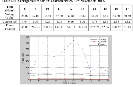
To know the characteristic of a PV, hourly readings was taken for 10hours, values for
Voltage and Current using Voltmeter and Ammeter connected in parallel with the solar array
was gotten. The values of Power were gotten from calculation using the formula:
P = IV………1
Where, P = Power,
I = Current and
V = Voltage.
The table below shows the values of Voltage, Current and Power at different time of the day.
Table 4.0: Average values for PV characteristics. 19th November, 2016. Time
(Hour) 8 9 10 11 12 13 14 15 16 17
Voltage
(Volts) 28.07 39.03 38.83 37.80 37.80 38.60 38.70 32.7 33.80 30.60
Current (A) 1.64 5.30 7.24 4.73 6.46 8.31 6.78 1.86 2.88 1.82
Power
(Watts) 45.05 206.75 208.25 182.31 249.14 321.98 262.69 62.56 100.27 61.43
Fig. 4.0: Graph of Current, Voltage and Power against Time.
Therefore, the essence of the PV test, result and graph is to show the sensitivity,
performance and reliability of the PV system and how it can work effectively using the test of
every hour of the day.
Fig. 4.1: Graph of System Size against Cost.
The plotted graph (SYSTEM SIZE VS COST) above shows that the size of the solar module
5.0. CONCLUSION
Although initial cost for this kind of design seems high, the long run benefits tremendously
outweigh its possible alternatives.
The system has the ability of sustaining itself for a period of 25 to 30 years if operated as
recommended. At a certain time, the system begins to save money and in turn generates
income if connected to the grid. We have also learnt how the various components of this
system function together and can eventually take up any PV contract anywhere without fear
of failure. This photovoltaic system is therefore a great investment.
REFERENCES
1. J. Perlin. From Space To Earth (The Story Of Solar Electricity). Harvard University
Press: London, 1999.
2. G. John. Photovoltaic: Solar Electricity and Solar Cells in Theory and Practice. Internet:
http://www.solarserver.com, Oct, 2011; 21.
3. Solar Energy Technologies and Applications, CANREN:
www.canren.gc.ca/techappl/index.asp? caid=5&pgid=121, Sept. 4th, 2011 [4] K. Gil, “How do Photovoltaics Work?” Science News, 2004; 1(1): 4.
4. K. Gil “How do Photovoltaics Work?” Science News, 2004; 1(1): 4.
5. “Renewable Energy”. Internet: www.en.wikipedia.org/wiki/renewable_energy, Sept,
2011; 4.
6. “Renewable Energy advantages”. Internet:
http://www.wanttoknowit.com/advantages_of_ renewable energy, Sept, 2011; 4.
7. B. Bedford, et al. Principles of Inverter Circuits. John Wiley & Sons, Inc.: New York,