(UDC: 621.874:681.515.8)
Reduction of the drive acceleration of bridge cranes through judicious
choice of the load trajectory moving
V. S. Shcherbakov1, M. S. Korytov2*, E. O. Volf3
1
Siberian State Automobile and Highway academy (SibADI), prospect Mira 5, Omsk, Russia [email protected]
2
Siberian State Automobile and Highway academy (SibADI), prospect Mira 5, Omsk, Russia [email protected]
3
Siberian State Automobile and Highway academy (SibADI), prospect Mira 5, Omsk, Russia [email protected]
*Corresponding author
Abstract
The article dwells upon the results of study influence shape of path of load’s motion which given with using the sigmoidal functions of traversing single obstacle on the arc with suppression of load’s oscillations to the acceleration of the bridge crane's drive. The possibility of a simultaneous significant reduction of the maximum speed, maximum and average values of acceleration, absolute error of the load position and the full work of the drive of one of the controlled axes of the overhead crane by changing the sigmoidal functions parameters that are produced changes in curvature of the arc for a fixed traveling time.
Keywords: bridge crane, PID-regulation, sigmoid functions, acceleration of suspension drive, load, oscillation suppression.
1. Introduction
For the bridge crane (BC) which have a flexible rope suspension of the load, a serious problem are uncontrolled load oscillations at movement, which significantly reduces the accuracy and the efficiency of implementing works. Optimization of the trajectory of transferring point of load suspension located on the load trolley BC, which is reduced optimization of the process controlling the bridge and trolley’s drive mechanisms is one of the possible ways to solve this problem (Blackburn et al. 2010; Denisenko 2007). There was proposed to use proportional-integral-differential (PID) independently control by two controlled coordinates of the bridge and load trolley (Denisenko 2007; Koritov et al. 2004).
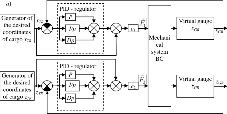
Implementation of smoothed path of motion specified type without high-frequency oscillations (wobble) of both the cargo and the point of suspension - possible with using PID-regulation, and at relatively low values of acceleration developed by the point of suspension.
Fig. 1. Diagram of connections of model of mechanical subsystem of the bridge crane with PID-regulators
The conducted preliminary studies allowed to the conclusion of those using sigmoid functions for setting required time dependencies of the horizontal coordinates of a cargo at traversing (load bypass) single obstacle of a "wall" type, can significantly reduce or eliminate high-frequency oscillations not only of linear coordinate of cargo and of suspension, but the oscillations of velocities and accelerations of the suspension point in comparison with other methods of setting required trajectory of load movement (for example, using trigonometric sinusoidal time or coordinate functions or using consistent integration of graded jerk’s functions). At the same time, there is a significant decrease of the absolute values of acceleration of the suspension point, which become comparable with accelerations of load at the required ideal smooth trajectory.
2. Fundamental relations
A series of computational experiments on a simulation model was conducted for study complex BC dynamic system’s performance with PID regulators. As an example given the results of modeling the process of load bypass of a single obstacle of a "wall" type on a levelled trajectory assigned by horizontal coordinates X0, Z0 space in a fixed Cartesian coordinate system O0X0Y0Z0
by logistic sigmoid time functions of the form (Shcherbakov et al. 2015; Tolochko, Bazhutin 2010):
(
)
(
a( )t c)
x
ТRt,a,c l e
X = 1+ − ⋅ − ; (1)
(
, , , ,) (
)
(
(
1 1( 1))
(
1 2( 2))
)
2 2 1 1
c t a c
t a sx
x
ТRt a c a c s k e e
Z = ⋅ + − ⋅ − ⋅ + − ⋅ − ; (2)
const
=
ТR
Y , (3)
Generator of the desired coordinates of cargo zТR Generator of the desired coordinates
of cargo xТR Mechani
cal system
BC c1
P
I/p
Dp
PID - regulator
c2
P
I/p
Dp
PID - regulator
Virtual gauge xGR
Virtual gauge zGR
xGR
zGR
zТR
xТR
where t - time; XTR, ZTR - the required coordinates of load in the horizontal plane at time moment t; YTR - the required constant vertical coordinate of cargo; a, c, a1, c1, a2, c2 -
parameters of sigmoid functions; lx - the length of the movement along the axis X0 between
starting and ending points of the required load trajectory (this points have zero coordinate Z = 0); sx - value of maximum arc’s displacement of the required trajectory of load along the axis Z0
(laterally to avoid obstacles); ksx - the correction coefficient of maximum value of the lateral displacement,
( )
(
1 1)
(
2( 2))
1
1 a c c a c c
sx e e
k = + − ⋅ − ⋅ + − ⋅ − . (4)
Function (2) is the product of two sigmoid functions of the type (1) - increasing and decreasing with different time of inflection’s points. The parameters c, c1, c2 set the time of
inflection’s points of sigmoid functions, and parameters a, a1, a2 - the rate of change (the rate of
growth or decline is determined by the sign) of functions [8].
It has been hypothesized that a slight change in the shape of load’s path of motion when it bypass a single obstacle by changing the relevant parameters of sigmoidal functions while maintaining a constant value of the travelling time may cause a significant decrease in the mean values of velocities and accelerations of the suspension point. I.e. open the reserves to reduce the requirements for the dynamic characteristics of the BC’s drive through using of sigmoidal functions of specifying load’s path of motion with PID-regulators, which provide reduction of high-frequency load’s oscillations (Shcherbakov et al. 2015).
During a series of considered experiments, for changing the trajectory shape there was varied the parameter kud - accepted coefficient of relative distance from each other of two multiplied simple sigmoid functions in terms (2).
The conditional time of moving suspension point of the load TP, which, according to the results of the research, is entered in the limits TP = 1,33333∙TGR, takes a fixed value TP = 30 s, where TGR - conditional time of the load’s movement.
At using threshold value of the sigmoid function P = 0,999, at achievement of which a given load’s movement was considered complete, the parameters of the sigmoid function (1) were determined by Shcherbakov et al. 2015
(
1 1) (
2)
ln /P / T /
a= − − GR ; c=2⋅TGR/2,. (5)
where TGR=0,75∙TP.
Parameters of function (2) were initialized by the following dependencies (Shcherbakov et al. 2015)
GR ud GR
ud T c c k T
k c c a a a
a1= , 2=− , 1= − ⋅ , 2= + ⋅ . (6)
Proportional coefficient, integral and differential constants of PID-regulators of controlling drives of the bridge and trolley’s movement in this task were possessed the values: P = 20; I = 5; D = 5 correspondently (Shcherbakov et al. 2015).
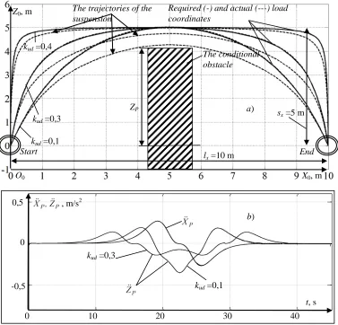
kud parameter was varied from 0,1 to 0,4, which caused a corresponding change of shaped and curvature of predetermined load path of motion (Shcherbakov et al. 2015). In the Fig. 2, as an example shows implementation of two realizations the assignments a desired trajectory (1) - (6) for the values kud = 0,1, kud = 0,3 and kud = 0,4. With kudincrease of 0,1 to 0,3 the maximum acceleration by the trolley coordinates ZP reduced about 2 times, when accelerations of the
additional restrictions when bypass a single obstacle of a "wall" type in the absence of other obstacles in the workspace. When kud increases the trajectory curve of the suspension point path of motion more away from the axis of fixed coordinate system O0X0, that allows doing the
bypass by the load of a single obstacle of a "wall" type largest size with a lower acceleration (in the direction of the axis O0Z0). Fig. 2 shows that becomes possible an increase in the thickness
of the "wall" (its size on axis O0X0).
Fig. 2. Diagrams of Cartesian coordinates of the load center’s point and the suspension point (a) and acceleration of the suspension point (b) at realization of traversing single obstacle with the
use of PID-regulation (example)
BC parameters and its working process have the following values: the load cable length 12 m; the magnitude of the required movement of the load along the axis O0X0 - 10 m; the magnitude
of lateral displacement for obstacles’ bypass along the axis O0Z0 - 5 m; the mass of the bridge -
3500 kg; the mass of the load trolley - 1250 kg; load weight - 100 kg; the presented coefficients of decrement by the angular coordinates of deviations of the load cable from the vertical in two mutually perpendicular planes - 100 N∙m∙s/rad (Shcherbakov et al. 2015).
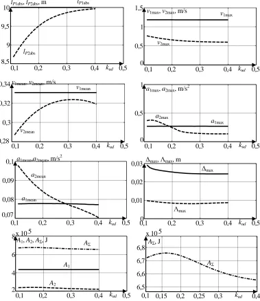
On Fig. 3 shows graphs of some parameters that characterize the BC’s working process depending on the value of the coefficient kud. As an example there are presented obtained during
0 10 20 30 40
-0,5 0 0,5
t, s , m/s2
kud =0,3
kud =0,1 Z0, m
X0, m
kud =0,3
kud =0,1
O0
The trajectories of the suspension
Required (-) and actual (---) load coordinates
End Start
kud =0,4
The conditional obstacle
а)
b) ZP
sx =5 m
the described series of computational experiments: the absolute movements of the bridge and load trolley correspondingly (at the realization of the specified trajectory) lP1abs, lP2abs, m; the
maximum velocities of the bridge and load trolley ’s movements v1max, v2max, m / s; the average
velocities of the bridge and load trolley’s movements v1mean, v2mean, m / s; the maximum
accelerations of the bridge and load trolley’s movements a1max, a2max, m/s2; the average
accelerations of the bridge and load trolley ’s movements a1mean, a2mean, m / s2; the maximum
absolute error of the trajectory’s realization Δmax; the average absolute error of realization of the
trajectory Λmax, m; the work, implemented by the drive of the bridge A1, J; the work,
implemented by the drive of the load trolley cart A2, J; the total work of the drives AΣ, J.
Fig. 3. The indices for assessing the working process of the bridge crane depending on parameter of setting the sigmoidal function kud, which determines the shape of an arc given
trajectory (example)
0,1 0,2 0,3 0,4 0,5
8,5 9 9,5 10
kud lP1abs, lP2abs, m lP1abs
lP2abs
0,1 0,2 0,3 0,4 0,5
0 0,5 1 1,5
kud v1max, v2max, m/s v
1max
v2max
0,1 0,2 0,3 0,4 0,5
0,3 0,32 0,34
kud v1mean
v2mean
0,28
v1mean, v2mean, m/s
0,1 0,2 0,3 0,4 0,5
0 0,5 1
kud a1max, a2max, m/s2
a1max
a2max
0,1 0,2 0,3 0,4 0,5
0,08 0,09 0,1
kud a1mean,a2mean, m/s2
a1mean
a2mean
0,07
0,1 0 0,2 0,3 0,4 0,5
0,01 0,02 0,03
kud
Δmax, Λmax, m
Δmax
Λmax
0,1 0,2 0,3 0,4 0,5
2 4 6 8 x 10 5
kud A1, A2, AΣ, J
A2
A1
AΣ
0,15 0,2 0,25 0,3 0,4
6,5 6,6 6,7 6,8
x 10 5
kud 0,1
The measuring sensors, in the form of additional information outlets embedded in blocks of mechanical joints SimMechanics Second Generation measuring movements and velocities by the individual degrees of joints’ freedom were used during the working process for giving the values of the above parameters (Shcherbakov et al. 2015).
3. Conclusions
Analysis of the dependences shown in Fig. 3 allows us to conclude that increasing in the coefficient kud, approximating the shape of the desired path to the rectangular, makes it possible to reduce the requirement imposed on speed of the bridge and load trolley’s drives. The maximum and average values of acceleration, maximum speed, total work performed by the drives reduces of 3 to 50 % during simultaneous increasing the accuracy of load’s movements. On the 18 % reduced the maximum absolute error of the trajectory’s realization Δmax. At the
same time, the average velocity movement of the trolleys suspension point v2mean slightly (on 14
%) increases.
The regression dependence of all indicators of evaluates the overhead crane workflows that shown in Fig. 3 on the value of the coefficient kud in the studied range from 0,1 to 0,4 were obtained:
m; 10
1 =
lPabs
m; 5708 6 122 26 9992 71 3365 77 7706
18 4 3 2
2 = , k + , k , k + , k + ,
lP abs − ⋅ ud ⋅ ud − ⋅ ud ⋅ ud
m/s; 1802 1 03901 0 25014 0 65178 0 60016
0 4 3 2
max
1 = , k + , k , k + , k +,
v − ⋅ ud ⋅ ud − ⋅ ud ⋅ ud
m/s; 01893 1 10898 3 83320 7 70079 6 17528
0 4 3 2
max
2 = , k , k + , k , k +,
v − ⋅ ud − ⋅ ud ⋅ ud − ⋅ ud
m/s; 33099 0
1 = ,
vmean m/s; 21466 0 92362 0 86223 2 21564 4 00416
3 4 3 2
2 = , k + , k , k + , k + ,
vmean − ⋅ ud ⋅ ud − ⋅ ud ⋅ ud
; m/s 26549
0 2
max
1 = ,
a ; m/s 36915 0 6402 16 348 123 463 343 418
328 4 3 2 2
max
2 = , k + , k , k + , k ,
a − ⋅ ud ⋅ ud − ⋅ ud ⋅ ud−
; m/s 07744 0 00049 0 02237 0 10116 0 0940
0 4 3 2 2
1mean= , k , k + , k + , k + ,
a ⋅ ud − ⋅ ud ⋅ ud ⋅ ud
; m/s 12801 0 34147 0 59559 0 39144 0 62085
1 4 3 2 2
2mean= , k + , k + , k , k + ,
a − ⋅ ud ⋅ ud ⋅ ud − ⋅ ud
m; 04632 0 27596 0 35664 1 04095 3 58032 2
Δ 4 3 2
max= , ⋅kud − , ⋅kud +, ⋅kud − , ⋅kud+ ,
m; 01071 0 00647 0 22702 0 88317 0 96905 0
Λ 4 3 2
max=− , ⋅kud + , ⋅kud − , ⋅kud + , ⋅kud+ ,
J; 69 434808 1 , A = J; 59 171413 06 1141005 4 6292665 92 13359483 83
9980142 4 3 2
2= , k + , k , k + , k + ,
A − ⋅ ud ⋅ ud − ⋅ ud ⋅ ud
. , + k , + k , k , + k , =
The most significant (up to 50 %) reduced the required maximum acceleration of the trolley BC a2max, when changing the shape of the desired path of elliptical to the rectangular,
which opens the possibility of using the more economy drive in this case for the load trolley.
Besides, approach of the set trajectory to rectangular (in consider experiment the limit of increase in kud making 0,4) allowed to increase the sizes of a conditional obstacle both along an axis of O0X0, and along an axis of O0Z0. At the same time the further increase in kud led to
gradual increase of an average error of realization of a trajectory Λmax at stabilization of values
of a2max. Proceeding from it, the methodology of a choice of a reference trajectory of moving of
cargo for detour of an individual obstacle consisted in maximization of value of factor of kud
(kud→max) at performance of the set restriction on Λmax. Parameters of overall dimensions lx
and sx of the required trajectory was thus determined by technology of work, in particular, lx – coordinates of initial and final points of moving of cargo. sx are offered to be accept equal to the size of an obstacle of ZP along an axis of O0Z0 with addition of the amendment on an error of
realization who are expedient for set within 0,5 … 1 m:
) 1 5 , 0
( …
+ = P
x Z
s (8)
The original contribution of authors consisted in working out of mathematical model of BC with PID-regulators (see. Fig. 1). For the first time it is offered to use PID-regulators for synthesis of an optimum trajectory of movement of a point of the suspension of cargo without rocking in a mode of real time. Also the idea of use for the task of a reference trajectory of movement of cargo on the flexible suspension of sigmoid function (moving of the bridge) and products two sigmoid of functions (moving of the cargo cart) are original.
Have a certain novelty the findings that the form of the set trajectory for detour by cargo of the individual obstacle, set in the factor kud, allowed to significantly reduces the maximum acceleration of the BC suspension point.
These relationships can be used for multi-criteria optimization of BCs workflow with the application of the above particular criteria of accuracy, speed drive, the size of the obstacles, etc.
Извод
Смањење убрзања мотора код мосних дизалица правилним избором
криве оптерећења током кретања
V. S. Shcherbakov1, M. S. Korytov2*, E. O. Volf3
1
Siberian State Automobile and Highway academy (SibADI), prospect Mira 5, Omsk, Russia [email protected]
2
Siberian State Automobile and Highway academy (SibADI), prospect Mira 5, Omsk, Russia [email protected]
3
Siberian State Automobile and Highway academy (SibADI), prospect Mira 5, Omsk, Russia [email protected]
*главни аутор
Резиме
путање са пригушењем осцилација оптерећења променом убрзања погона мосне дизалице. Могућим истовременим смањењем максималне брзине, максималне и средње вредности убрзања, апсолутне грешке позиционирања терета и укупног рада по једној од контролисаних оса мосне дизалице променом сигмоидних параметара функције мења се крива оптерећења током фиксног времена кретања.
Кључне речи: мосна дизалица, ПИД регулација, сигмоидне функције, убрзање
пригушења мотора, пригушење осцилација.
References
Blackburn D, Singhose W, Kitchen J, Patrangenaru V, Lawrence J (2010). Command Shaping for Nonlinear Crane Dynamics, Journal of Vibration and Control, 16, 477-501.
Denisenko VV (2007). Varieties of PID-regulators, Automation in the industry, 6, 45-50. Korytov MS, Glushets VA, Zyryanova SA (2004). Modeling of labor movements of automatic
crane using SimMechanics and Virtual Reality Toolbox, Exponenta Pro. Mathematics in applications, 3-4, 94-102.
Korytov MS, Zyryanova SA (2004). Modeling of the automatic crane’s dynamic system using packet burst «SIMMECHANICS» of the system MATLAB, Omsk Scientific Bulletin, 4, 88-90.
Mitchell, TM (1997). Machine Learning, WCB/McGraw-Hill.
Shcherbakov VS, Korytov MS, Kotkin SV (2012). Automation system of modeling wrecker luffing cranes: monograph, SibADI, Omsk.
Shcherbakov VS, Korytov MS, Volf EO (2014). A method for increasing the accuracy of the trajectory of object’s movement by luffing crane using compensation of its unmanaged spatial oscillations, Mechanization of construction, 2, 21-25.
Shcherbakov V, Korytov M, Sukharev R, Volf E (2015). Mathematical modeling of process moving cargo by overhead crane, Applied Mechanics and Materials, 701-702, 715-720. Shcherbakov VS, Korytov MS, Volf EO (2014a). Improving the accuracy and speed of load's
movements to desired trajectory by a crane bridge type, Systems. Methods. Technologies, 4(24), 52-57.
Shcherbakov VS, Korytov MS, Volf EO (2014b). The system of suppression the load's spatial fluctuations which transported by overhead crane, SibADI Bulletin, 6(40), 56-61.