(DOI: 10.24874/jsscm.2018.12.02.07)
Modeling and Simulation of a Circular Valveless Micropump
T. Barkat1*, F. Z. Kadid1, M. S. Aggoune1 and R. Abdessemed1
1LEB Research Laboratory, Department of Eletrical Engineering, Faculty of Technology,
University of Mostefa Benboulaid-Batna2, Batna 05000, Algeria e-mail: [email protected]
e-mail:[email protected] e-mail:[email protected] e-mail:[email protected]
*corresponding author
Abstract
In this paper, the behavior of a valveless, diaphragm-founded, piezoelectric micropump is studied and simulated. The nature of the piezoelectric actuator is a PZT-5H piezo-disk and the diaphragm is made of Silicon dioxide (SiO2). Applying Fluid-Structure Interaction (FSI) approach, the simulation for the valveless micropump is carried out in COMSOL 3.5 Multiphysics. Also, electro-structure mating between deformation of a piezoelectric disk due to an applied voltage and resulting displacement of the membrane is considered. From the obtained results, the optimum design required a 0.5 mm membrane and 0.5mm piezo actuator. Numerical simulations are reported to study respectively the effects of the voltage on the diaphragm deflection and the nature of the fluid on the net flow rate.
Keywords: Piezoelectric peristaltic pump, Valveless Micropump, Piezoelectric actuator, Finite element method, Fluid flow.
1. Introduction
polymer-founded actuation mechanisms, Shoji (2016). Among diverse actuation possibilities, piezoelectric (PZT) actuation gives advantages in terms of big deflection, high actuation force, fast mechanical response and facility of integration. When an electric voltage is applied across the bounds of a diaphragm, it has the ability to deform it in the direction of polarization, Sutradhar (2013). Following (Khare et al. 2014, Singh at al. 2015), a lot of studies has been performed concerning planer valveless micropump. In (Yang et al. 2015), the authors have investigated the effects of the frequency on the flow rate. Equation Chapter 1 Section 1
In this work, 3D modeling and simulation of a valveless piezoelectric micropump are carried out using a finite element method with Comsol 3.5 software. Different characteristics are obtained. In this paper, the displacement and the flow rate for the two simulated fluids water and blood are found and analysed. Finally, a comparison of the results is done.
2. Principle of operation
A particular type of micropumps which has received a lot of attention in recent years is the diaphragm based-valveless type as exposed schematically in (Fig. 1), Lotto (2003). A diffuser is specified as a conduit with an expanding cross-sectional area in the flow direction and a nozzle is a conduit with decreasing cross-sectional area in the flow direction. The vibrating diaphragm forms the pumping mechanism. The micropump operation is founded on the fluid flow rectifying properties of the two nozzle ̸ diffuser elements. The micropump cycle is split into a supply mode and a pump mode. During the "supply mode" the cavity volume increases and a larger quantity of fluid flows into the cavity across the input element, which acts as a diffuser. In the "pump mode", the actuator decreases the chamber volume, resulting in higher pressure inside the chamber. As a result, a larger quantity of fluid flows out of the chamber through the output element, which behaves as a diffuser, then through the input element, which acts as a nozzle (Yinghua et al.2014).
Fig. 1. The working principle of a piezoelectrically actuated valveless micropump in supply mode and in pump mode.
3. Governing equations
pressures. Qinlet and Qoutlet are respectively the volume flow rates of the inlet and outlet. The variation of the volume into the chamber due to the vertical displacement of the membrane can be expressed as, (Olsson A and al. 1995):
0sin( ) c
V =V wt (1)
Where
w=2 .f
o v 0 V =K x
c
V : volume in the chamber ;
0 0
V : the amplitude of the variation in the volume;
v
K : constant;
o 0
x : the amplitude of the deflexion in the center of the diaphragm;
o
f : the frequency of the pump;
o
t : the time.
To model the pumping flow rate, the following assumptions are made:
- The total pressure loss inside the pump is caused by the local pressure loss of the flow through diffuser and nozzle.
- The pressure inside the chamber is uniform.
- The pressures at inlet and outlet are Pin = Pout = 0.
- The inlet and outlet elements have identical geometry.
The pressure downfall across a nozzle and a diffuser can be written as:
2 2 2 and 2 n n n d d d v P v P = = (2)
where ξn and ξd are pressure loss coefficient of the nozzle and diffuser. 𝑣𝑛 and 𝑣𝑑are the fluid flow velocities in the narrowest parts of the nozzle and diffuser, (Olsson A and al. 1995)
The flows Qn and Qd across the nozzle and diffuser directions are respectively expressed as: 1 2 2 1 2 1 and 2 2 n n n d d d P Q A P Q A = = (3) Where:
c c
inlet outlet
V dP V
Q Q
P dt t
+ = −
(4)
4. COMSOL Multiphysics Modeling
The study of a valveless piezoelectric micropump results in coupled partial differential equations in electrical, mechanical and fluid-solid domain. These either cannot be solved analytically or lack an exact analytic solution due to the intricacy of the boundary conditions or domain. The finite element method is used to solve the problem. The FEM-based software Comsol 3.5 is used to simulate the behavior of the micropump, (Nayana L and al.2012).
5. Piezoelectric actuator simulation
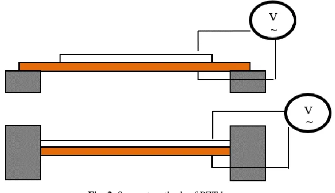
The piezoelectric actuator is the most fundamental part of the behavior of a micropump, as the driving equipment and the life time of the micropump depend on it. The way the piezoelectric actuator is supported has a direct influence on the maximum deflection of membrane and thus on the amount of liquid flow pumped through the apparatus. The two positions of the membrane are exposed in (Fig. 2).
Fig. 2. Support methods of PZT buzzer
The different values of materials properties used in this paper have been provided in Table 1 and Table 2:
Materials Young’s modulus Poisson’s ratio Density
PZT-H5 2.0×10¹¹ [Pa] 0.33 7500[Kg/m3]
SiO2 70×109 [Pa] 0.17 2200 [Kg/m3]
fluid Density (kg/ m3) Dynamic viscosity (kg/m)
Water 1000 0.001
Blood mimicking 1050 0.004
Table 2. Parameters for the flow field simulation
6. Results and discussions
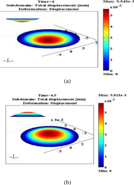
The simulation results exposed in (Fig. 3a) and (Fig. 3b), show that the displacement profile of the membrane is a parabolic surface, in which the maximum value is obtained at the center of the membrane where as the minimum value happened along the fixed boundaries.
(a)
(b)
The variations of the deflection of the diaphragm for different applied voltages are studied. It is observed that the diaphragm deflection has a nearly linear dependence on the applied voltage (Fig. 4)
Fig. 4. Variation of diaphragm deflection with different applied voltages
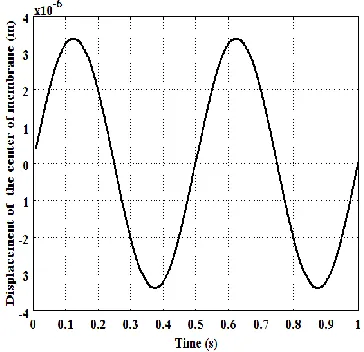
The displacement curve at the center of the diaphragm over time is shown in (Fig. 5). The diaphragm linked to the piezo-disk rises between t = 0.0 s and 0.13 s, and drops from t = 0.13 s to 0.36s, and rises again between t = 0.36s and 0.5s to complete a cycle.
Fig. 5. Displacement in the centre of the membrane in terms of time.
When a supply voltage of 100 V is applied, the simulation results show that the deflection is maximum at the center and zero at the edges, as expected theoretically and as shown in (Fig. 3). Fig. 7 and Fig. 8 show streamline patterns for frequency of 5Hz in nozzle-diffuser micropump. During the supply mode, the diaphragm deflects upward and thus generates a negative pressure inboard the pump chamber. Due to this fact, the fluid enters the pump chamber through the inlet and outlet. While during the pumping mode, the diaphragm deflects down into the pump chamber, thus increasing the pressure of the fluid within the pump chamber as shown in (Fig. 6).
0 20 40 60 80 100 120 140
0 0.5 1 1.5 2 2.5 3 3.5 4 4.5
5x 10
-6
Voltage (v)
Fig. 6. Total Displacement of Diaphragm
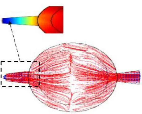
Fig. 8. Streamline velocity contours inside the chamber of micropump: suction stroke.
When the micropump is in a supply mode, the pressure inside the chamber is as shown in (Fig. 9a) with an input signal amplitude of 100V and a freqency of 5 Hz. The velocity distribution in (Fig. 9b) shows the fluid flowing into the chamber from both inlet (left) and outlet (right). The maximum flow velocities reach respectively 4.20*10−3 m/s and 2.26*10−3 m/s at the inlet and outlet after a steady state period of 3s.
(b) velocity flow
Fig. 9. Simulated characteristics. (a) Pressure contours; (b) velocity flow in inlet and outlet.
To compare the performances of the studied valveless micropump, an analysis is carried out with two liquids: water and blood of different viscosities.
Fig. 11. Flow rate of mimicking blood at the inlet and outlet of the micropump.
The simulations of flow rate of diffuser and nozzle during a cycle are shown in Fig. 10 and Fig. 11. The angle of the diffuser and the nozzle is 11.300. The difference between the inlet flow rate and outlet flow rate is the net flow rate of the micropump.
7. Conclusion
In this paper, a piezoelectric micropump chamber is considered. The displacement of the membrane has been simulated using COMSOL 3.5 software. When we applied a sinusoidal voltage to the piezoelectric micropump, the magnitude of displacement depended linearly on the input voltage.
The results show that when a piezoelectric actuator is driven by voltage, the maximum displacement always occurs in the middle of the diaphragm.
The 3D study of the flow of the micro pump in the case of two fluids water and the blood, shows that the flow of water is greater than the flow of blood, because the dynamic viscosity of the blood is higher than that of water. The high viscosity reduces the pumping efficiency and causes the flow rate to decrease by 20 %.
References
Bothe D, Schäfer M (2014). Numerical modeling of fluid-structure interaction with rheologically complexfluids, Thesis,universitäts undLandesbibliothek Darmstadt , Allemagne.
Kumar S, Balvinder J, Kumar Deb R, Chandra Jha V, Ahmed Khan, I (2012). Desgin And Fabrication Of A Three Dimensional Valveless Micropump With Shape Deposition Manufacturing Process (Sdm), International Journal of Research in Engineering & Applied Sciences (IJREAS), 2, 805-824.
Lotto C (2003). Conception d’une micropompe utilisant le principe des valves dynamiques et réalisation d’un prototype bon marché adapté aux applications biochimiques de types « lab-on-a-chip » .Projet de semestre, Laboratoire de Microsystèmes (EPLF.LMIS2).Lausanne. Nayana L, Manohar P, Babu S (2012). Design and Simulation of Valveless Piezoelectric
Micropump, excerpt From The Proceedings of The COMSOL, Conference In Bangalore. Nagakalyan S, Raghu Kumar B (2013). Analysis of piezoelectric micro pump, International
Journal of Mechanical Engineering and Robotics Research (IJMERR), 101-107.
Olsson A, Stemme G, Stemme E (1995). A valve-less planar fluid pump with two pump chambers, Elservier sensors and actuators a, 46-47, 549-556.
Singh S, Kumar N, George D, Sen AK (2015). Analytical modeling, simulations and experimental studies of a PZTactuated planar valveless PDMS micropump, Elsevier Sensors and Actuators A 225, 81–94.
Shoji E (2016). Fabrication of a diaphragm micropump system utilizing theionomer-based polymer actuator, Elsevier Sensors and Actuators B 237, 660–665, Japan
Sutradhar S (2013). Optimization of Geomerty of Microfabricated Piezoelectric Actuator, International Journal of Engineering trends and Technology, 4,580-585.
Yinghua X, Weiping Y, Tun C, Li G (2014). Study on the Valveless Micropumps with Saw-tooth Microchannels, 11th IEEE International Conference on Control & Automation (ICCA), 18-20, Taichung, Taiwan, June.