R E S E A R C H
Open Access
Bio-inspired optimization algorithms
applied to rectenna design
Menglong He
*, Zhao Wang, Mark Leach, Zhenzhen Jiang and Eng Gee Lim
*Correspondence: [email protected] Department of Electric engineering, Xi’an Jiaotong-Liverpool University, Ren’ai road 111, Suzhou, People’s Republic of China
Abstract
A comparative study of the use of bio-inspired optimization technologies including the Cuckoo Search (CS) algorithm, the Differential Evolution (DE) algorithm, and
Quantum-behaved Particle Swarm Optimization (QPSO) in the design of microstrip patch antennas for use in RF energy harvesting systems is presented. Radio frequency (RF) energy harvesting is considered as an eco-friendly energy source and has become a focus of intense research especially for use in distributed sensor networks. In a RF energy harvesting system, the antenna is responsible for capturing RF signals over a certain frequency band, and it is a vital element in determining the performance of the RF energy harvester. In this paper, a new mathematical weighted evaluation model involving antenna efficiency, center frequency, and bandwidth is proposed to evaluate the performance of a rectangular microstrip patch antenna (RMPA) for a RF harvesting system based on both the transmission-line model and the cavity model. With the evaluation model as the objective function, bio-inspired optimization approaches are utilized to determine the geometrical parameters of the optimal antenna based on given constraints. Moreover, the optimised designs of an antenna for harvesting energy from the Global System for Mobile Communications (GSM) frequency band are proposed via the mathematical model and bio-inspired optimization approaches using simulations. Furthermore, a comparative study of the DE, CS, and QPSO techniques is conducted via the evaluation of the properties of the antenna designs.
Keywords: RF harvesting system, Microstrip antenna, Cuckoo Search (CS) algorithm, Differential Evolution (DE) algorithm, Quantum-behaved particle swarm optimization (QPSO)
Background
With the advance of technologies including the Internet of Things (IoT) and wearable electronics, the demand for mobile electrical devices has surged. Battery depletion has become a fundamental bottleneck which limits the performance of these devices [1]. Con-sidering the conventional fact that batteries have to be replaced or replenished manually after depletion, deeper implications exist for devices such as implantable heart pumps for which the replacement or recharging of the battery by cable is inconvenient and high-cost [2]. RF energy harvesting technology provides an alternative to this and has recently received significant attention in the research community demonstrating its potential as a sustainable energy source for low power electronics [3–7].
The general anatomy of an RF energy harvester has been explained and examined. Some state of the art designs for receiving antenna including both narrow-band and
broad band antennas have been introduced. A mathematical weighted evaluation model involving antenna efficiency, center frequency, bandwidth, and gain was proposed to evaluate the performance of a RMPA for a RF harvesting system.The heuristic optimiza-tion approaches CS, DE, and QPSO were introduced and then utilized to give optimal designs for a GSM1800 receiving antenna. The proposed optimization algorithms suc-cessfully achieved optimal solutions under two different antenna size constraints. The overall comparison between QPSO, DE, and CS showed that the DE based optimization design approach provides the best solution and hence has the best globally optimum value search ability. This can significantly enhance antenna performance. Moreover, among the three optimization approaches, the CS algorithm has the best robustness. Furthermore, the simulations using QPSO based algorithm indicate its superiority displaying a faster convergence speed than DE and CS in the application of solving a complex electromag-netic problem. The advance of wireless communication has been boosting the power density of ambient RF energy. Among various sources of available ambient RF energy, the GSM frequency bands, including GSM1800 and GSM900, the Industrial, Scientific and Medical (ISM) band and the 3G band are the most promising to be explored. The aver-age power densities of the conventionally utilized frequency bands measured in 2012 at all underground stations in London are summarized in Table 1 [8].
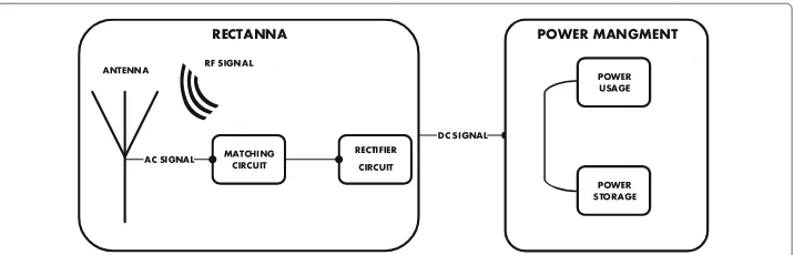
In brief, the RF energy harvester has the capability to convert RF signals (AC signal in nature) from ambient RF energy sources into a DC source. A typical centralized architec-ture of a RF energy harvesting system is shown in Fig. 1, it has two main components: a power management component and a rectenna. The rectenna consists of a receiving antenna, a matching circuit and a rectifier [4, 6]. The power management module has two approaches for controlling the incoming energy flow: harvest-use and harvest-store-use. The receiving antenna is responsible for capturing RF signals in the design frequency band, and it is a vital element in determining the performance of the energy harvesting system. Microstrip antennas have been greatly utilised in many communication tech-nologies due to their low profile structure and low manufacturing cost [9]. In this study, the rectangular microstrip patch antenna (RMPA) is chosen for the rectenna design. The design will be optimized using 3 bio-inspired optimisation techniques The optimisation of a microstrip antenna for a RF energy harvester can be interpreted as a multi-objects nonlinear optimization problem. The solutions for an optimal patch antenna design can be attained by heuristic optimization algorithms.
Recently, considerable research has been directed towards the enhancement of antenna performance in RF harvesting systems. A variety of types of antenna design have been investigated including: fractal antennas, microstrip antennas and monopole antennas
Table 1Average RF power density in London [8]
Band name Frequency band Average power density
GSM1800 (BTx) 1805 MHz∼1880 MHz 84 nW/cm2
GSM1800 (MTx) 1710 MHz∼1785 MHz 0.5nW/cm2
GSM900(BTx) 925 MHz∼960MHz 36nW/cm2
GSM900(MTx) 880 MHz∼915MHz 0.45 nW/cm2
3G (BTx) 2110 MHz∼2170 MHz 12 nW/cm2
3G (MTx) 1920 MHz∼1980 MHz 0.46 nW/cm2
Fig. 1Architecture of RF harvesting system. This figure shows a typical centralized architecture of a RF energy harvesting system, including two main components: a power management component and a rectenna
[10–12]. Table 2 shows the antenna performance of some state of art designs. As shown in Table 2, research efforts have been made for broad-band antenna(typical on order of 1GHz) as in [13–17, 42], and for narrow-band antenna in [10, 39–41, 43]. The dipole antenna is the focus of the work in [13, 16], and the monopole in [11, 41]. Authors in [17, 39, 40, 43] have demonstrated the excellent performance of the microstrip antenna. Nevertheless, most of the designs that have been mentioned previously do not consider the minimization of antenna size, which could potentially limit the application of the RF harvester. In [18–23], heuristic optimization approaches including the DE and CS algo-rithms have been utilized to determine the geometrical characteristics of the optimal patch antenna. Conventionally, patch antennas suffer from a narrow bandwidth. Accord-ingly, PSO and curve fitting have been introduced in [18], and the overall bandwidth of the inverted E-shaped microstrip patch antenna was increased by 15%. Authors in [20–23] have proposed mathematical models of the RMPA considering the center fre-quency as well as return loss, and the optimal designs are obtained via the CS, PSO, and DE algorithms. However, none of them involve improving antenna gain, widening antenna bandwidth, and minimization of antenna size.
Method
In a RF energy harvesting system, the antenna, which is responsible for receiving RF sig-nals over a certain frequency band, is an important element in the design of the RF energy harvester. The design of the antenna involves several parameters, some of which induce
Table 2Summary of performance of variety of up-to-date antenna design
Literature Antenna type Designed band Antenna gain Return loss
M. Arrawatia, et al. [39] Differential Microstrip 0.87 GHz∼1.05 GHz 8.5 dBi 17.2984 dB S. Ghosh, et al. [40] Microstrip 0.935 GHz∼0.96 GHz 4.0947 dB 12.82 dB
H. Saghlatoon, et al. [41] Planar Monopole 0.6 GHz∼1.5 GHz 3.432 dBi 27.5 dB A. Dadgarpour, et al. [42] Bow-tie 2.5 GHz∼3.9 GHz ≥10.9 dBi 27.68 dB M. W. Zeng, et al. [10] Fractal Loop 1.73 GHz∼1.84 GHz 3.2 dBi 31.25 dB M. Arrawatia, et al.[11] Triangular Monopole 0.85 GHz∼1.94 GHz ≥2 dBi 19.085 J. Wen, et al.[13] Dipole 1.7 GHz∼3.6 GHz 9.05 dBi 33.75 dB
D. Yang, et al.[14] Planar Quasi-Yagi 3.15 GHz∼10.65 GHz 7.6 dBi 24.714 dB R. Maher, et al. [15] Planar 2.1 GHz∼7GHz 11.4585 dBi 44.1499 J. Y. Li, et al. [16] Dipole 2.48 GHz∼9.51GHz ≥6dBi 19.08 K. P. Esselle, et al. [17] Microstrip 4 GHz∼9.5GHz ≥7.4 dBi 35
contradictory modifications of antenna performances. In this paper, a new mathematical weighted evaluation model involving antenna efficiency, center frequency, and band-width is proposed to evaluate the performance of a rectangular microstrip patch antenna (RMPA) based on both the transmission-line model and the cavity model. With the mathematic modeling of a RMPA, three bio-inspired optimization technologies includ-ing the Cuckoo Search (CS) algorithm, the Differential Evolution (DE) algorithm, and Quantum-behaved Particle Swarm Optimization (QPSO)are used to optimize the design of RMPA with certain constraints. The simulation processes and designed antennas’ per-formances are also presented and compared. With the evaluation model as the objective function, bio-inspired optimization approaches are utilized to determine the geometrical parameters of the optimal antenna based on given constraints.
The paper is organized as follows:“Mathematic modeling of RMPA”section introduces the basic architecture and properties of a RMPA, and a mathematical model is proposed based on the cavity and transmission line models. Additionally, the objective function and constraints for optimization are derived. The“Bio-inspired algorithms for antenna design” section describes the current implementation of the optimal antenna design algorithms including QPSO, CS, and DE. Finally, based on the performance of designed antennas, the properties of three bio-inspired algorithms are discussed and compared.
Mathematic modeling of RMPA
The efficiency of a RF energy harvester is defined as the ratio of output power (Pout) over
input power (Pin). Conventionally, the harvested RF power from the rectenna is expressed
as follows:
Pout =ηa·ηm·ηr·Pin (1)
where the ηa,ηm and ηr respectively represent the efficiency of receiving antenna,
impedance matching network, and rectifying circuit. The magnitude ofPT is correlated
with the design frequency band of antenna. Accordingly, the optimum antenna design for a RF harvesting system requires two features: high antenna efficiency and appropriate frequency band. In more detail, the performance of the antenna used for a RF energy har-vester mainly depends on the antenna gain, bandwidth, return loss, and center frequency. However, there is a trade-off between antenna size and performance.
Architecture of a RMPA
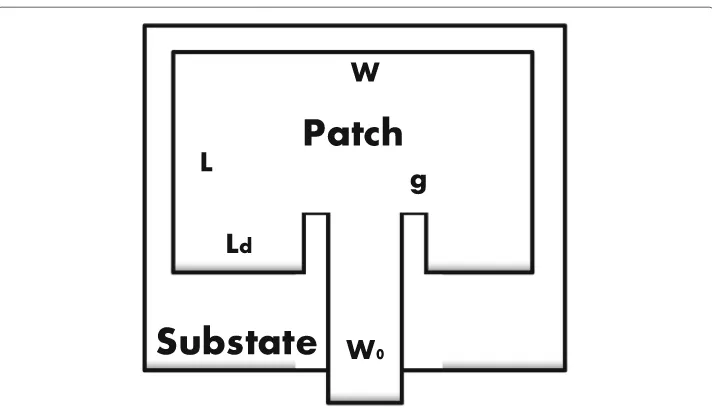
The typical architecture of a rectangular microstrip patch antenna (RMPA) with inset feed contains four geometric parameters (L, W, g, Ld) as shown in Fig. 2, and it
Fig. 2Architecture of a RMPA. This figure shows the typical architecture of a three-layer rectangular microstrip patch antenna (RMPA) with inset feed contains four geometric parameters (L, W, g, Ld)
Problem formulation
The objective function is to minimize the deviation between the designed antenna and the optimum antenna.
(W,L,y0,g,W0)=[δB,δAe,δG]·WT
Obj.Fun=min(W,L,y0,g)
(2)
Table 3Nomenclature of important parameters
F Center frequency of antenna Ae Antenna efficiency of antenna
B Band width of antenna RL Return loss of antenna
Pin Input power of rectenna Pout Output power of rectenna ηa Efficiency of antenna ηm Efficiency of matching circuit ηr Efficiency of rectifier circuit PT Transmitted power from source
W Width of RMPA L Length of RMPA
W0 Feed width of RMPA Ld Inset feed length
g Notch width ε0 Vacuum dielectric constant
Xmin Minimum constraint of antenna size Xmax Maximum constraint of antenna size
μ0 Vacuum permeability Zin Antenna input impedance
Voltage reflection coefficient VSWR Voltage standing wave ratio
Qrad Quality factor due to radiation losses Qc Quality factor due to conduction losses
Qd Quality factor due to dielectric losses Qsw Quality factor due to surface waves
Qt Total quality factor tanδ Loss tangent of the substrate material
G Antenna gain v0 The speed of EM wave
k0 Spatial angular frequency of wave Gabs Absolute gain
Prad Radiation power of antenna Umax Maximum radiation intensity
D0 Directivity of antenna with single slot DAF Directivity of array factor AF
eBW Efficient bandwidth ratio FAL Aimed lower conner frequency
FAH Aimed upper conner frequency FDL Designed lower conner frequency
FDH Designed upper conner frequency σ Conductivity of patch
Table 4Nomenclature of important parameters
Planck’s constant
V(r) Potential energy distribution
Mbest Best position of particle in the direction d
β Contraction-expansion coefficient
pj.d Local attractor of particle j in direction d
u Gaussian distributed number within [0,1]
k Random value within [0,1]
where W = [w1w2w3] is a weight matrix. Moreover,δF,δB,δAe, andδRLshows the
devi-ation between the performance of designed antenna and the performance of the optimal antenna. The inequality geometry constraints are five groups of inequations which can be obtained from the architecture of RMPA
⎧ ⎪ ⎪ ⎪ ⎨ ⎪ ⎪ ⎪ ⎩
g< L2 y0<L
Xmin<L<Xmax
Xmin<W<Xmax
(3)
Moreover, the geometrical requirement for applying the transmission line model of the RMPA is [9].
W h. (4)
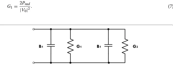
Input impedance of a RMPA
The input impedance of the RMPAZincan be obtained from the equivalent transmission
line circuit as shown in Fig. 3. The admittance of the antenna with two slots (Y1andY2)
is given by [24–26]:
Y1=G1+jB1 (5)
Y2=G2+jB2 (6)
whereG1=G2,B1=B2and owing to that the two slots of the antenna are identical.
With the field expression derived according to the cavity model [9, 25], the conductance of a single slot is defied as follows:
G1=
2Prad
|V0|2
. (7)
wherePradis defined as the radiated power which can be calculated by [25, 26]:
Prad= |
V0|2
2πη0
π
0 ⎡ ⎣sin
k0W
2 cosϑ
cos(ϑ)
⎤ ⎦ 2
sin3ϑδϑ. (8)
Accordingly, the conductance of the antenna is defined as:
G1=G2=
1 120π2
π
0 ⎡ ⎣sin
k0W
2 . cosϑ
cos(ϑ)
⎤ ⎦ 2
sin3ϑδϑ. (9)
Considering the mutual effect between the two slots, the total resonant input admit-tance of the RMPA with no inset feed can be obtained as [9, 24]:
˙
Y2=G1−jB1
Y =Y1+ ˙Y2=2(G1+G12)
(10)
where the mutual conductanceG12is [9, 24, 26].
G12=
1 120π2
π
0 ⎡ ⎣sin
k0W
2 cosϑ
cos(ϑ)
⎤ ⎦ 2
J0(k0Lsinϑ)sin3(ϑ)δϑ (11)
whereJ0is the Bessel function of the first kind of order zero, and accordingly the input
resistance for the inset feed case can be approximately expressed as [26]:
Zin=
1 2(G1+G12)
cos2π LLd
. (12)
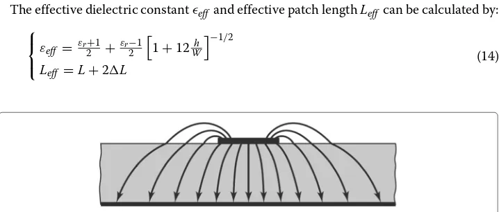
Resonant frequency of A RMPA
Owing to the fact that the dimensions of patch are not infinite along the length and width, the fields at the edges of patch is nonhomogeneous. Figure 4 shows typical electric field lines caused by the fringing effect, which makes the electric size of the patch larger than the physical dimensions. Thus, the effective dielectric constanteff and effective patch
widthLeffare introduced to take account of the fringing effect. Accordingly, the resonant frequency of the dominant mode of the RMPA is derived as [9, 24, 25].
FW,L,y0,g
= 1
2Leff√εreff√μ0ε0
(13)
The effective dielectric constanteff and effective patch lengthLeff can be calculated by:
⎧ ⎨ ⎩εeff =
εr+1
2 +
εr−1
2
1+12Wh
−1/2
Leff =L+2L
(14)
whereLis the normalized extension of the length and given as:
L=0.412h
εreff +0.3 Wh +0.264
εreff −0.258 Wh +0.8
. (15)
The notch width can be calculated based on the designed center frequency, and the empirical equation for which is proposed as [27]:
g= v0 2eff
4.65·10−12
f (16)
Antenna gain of a RMPA
Antenna gain is defined as the ratio of radiation intensity in a given direction to the inten-sity that would be obtained when the power accepted is isotropically distributed [9]. The relative gain is the ratio of power gain to the gain of a reference antenna [9]. Antenna gain is mathematically deified as [9, 24]:
G(W,L,y0,g)=4π
U(θ,φ) Pin
(17)
Antenna gain can also be expressed as a function of antenna directivity as:
G(θ,φ)=ecd[ 4πU(θ,φ)]=ecdDt (18)
Hence, antenna gain depends on radiation efficiency as well as directivity. The two parameters are calculated separately as follows.
The quality factor of the antenna, or the figure-of-merit, is representative of antenna loss, and it in general can be written as [9, 26]:
1 Qt =
1 Qrad +
1 Qc+
1 Qd +
1 Qsw
(19)
where the quality factors of various losses can be expressed as :
⎧ ⎪ ⎨ ⎪ ⎩
Qc=h
πfμσ Qd= tan(δ)1
Qrad= 2ωhGtr/Kl
(20)
As for the RMPA aperture operating in the dominantTMx010mode, theGt/landKcan
be calculated by [9].
⎧ ⎨ ⎩
K=
area|E|2dA
perimeter|E|2dl =
L
4
Gt/l= GW1
(21)
In an ideal situation the loss caused by conductionQcand the loss by surface waveQsw
can be ignored. Thus, the total loss can be approximately expressed as:
Qt=
QdQrad
Qd+Qrad
(22)
andecd, the radiation efficiency of an antenna, can be derived through the quality factor
as:
ecd=
Qt
Qrad = Qd
Furthermore, directivity, one of the most important antenna parameters, conventionally implies the ratio of maximum radiation intensity to the averaged value over all directions, and is expressed by:
Dt=
4πUmax
Prad
(24)
In the case of a RMPA with two radiating slots, the antenna directivity can be calculated by following equation [24, 25].
Dt=D0DAF (25)
where the directivity for an antenna with one slotD0is defined as [24]:
D0=
4π2W2
λ2 0 / ⎛ ⎜ ⎝ π 0 ⎡ ⎣sin
k0W
2 cosϑ
cos(ϑ)
⎤ ⎦ 2
J0(k0Lsinϑ)sin3(ϑ)δϑ ⎞ ⎟
⎠. (26)
Moreover, the directivity of the array factor AFDAFis calculated as follows [9]:
DAF =
2 1+G12/G1
(27)
Therefore, the antenna gain in dBi can be demonstrated by the following equation.
Dt=
8π2W2
λ2 0 / ⎛ ⎜ ⎝ ⎛ ⎜ ⎝ π 0 ⎡ ⎣sin
k0W
2 cosϑ
cos(ϑ)
⎤ ⎦ 2
J0(k0Lsinϑ)sin3(ϑ)δϑ ⎞ ⎟
⎠·(1+G12/G1)
(28)
Thus, the antenna gain can be obtained via the directivity and radiation efficiency of RMPA as shown in Eq. 29.
GW,L,y0,g= Qd
Qd+Qrad
Dt (29)
Deviation between the designed antenna gain and the optimal antenna gain (here we use 10 dBi as the desired gain) is defined as follows.
δGW,L,y0,g
=
10− Qd Qd+Qrad
Dt /10 (30)
Antenna efficiency of a RMPA
The overall antenna efficiency due to mismatch reflections andIR2losses is used to con-sider losses at the input terminals and within the antenna. Thus, the antenna efficiency can be written as:
Ae=erecd=ecd
1− ||2 (31)
In the transmission line model circuit, the return loss is determined by both the VSWR andwhich can be calculated using:
= Zin−Z0
Zin+Z0
VSWR= 11+|−||| (32)
In telecommunications systems, return loss is defined as the power loss for the signal reflected by a discontinuity during transmission, and it is mathematically defined as:
RL
W,L,y0,g
Assuming the characteristic impedance of the feed line is equal to 50, the return loss can be expressed by Eq. (34), The input independence of the RMPA has also been calculated using Eq. (12).
⎧ ⎨ ⎩
RL
W,L,y0,g
dB= −20 log10(||)= −20 log10ZZinin−+5050
RL
W,L,y0,g
dB= −20 log10
cos2(π
Ld)−100(G1+G12)
cos2(π
Ld)+100(G1+G12)
(34)
Therefore, the overall antenna efficiency can be expressed as follows:
Ae
W,L,y0,g
=erecd=
Qd
Qd+Qrad
⎛ ⎝1−
cos2πLd−100(G1+G12)
cos2π
Ld
+100(G1+G12) 2⎞
⎠ (35)
Additionally, the derivation between designed antenna efficiency and the optimal antenna efficiency can be defined as:
δAe
W,L,y0,g
= |(1−Ae)| (36)
Bandwidth of a RMPA
The magnitude of the bandwidth varies with VSWR. The bandwidth and percentage bandwidth of an antenna (VSWR≤2) can be calculated by:
⎧ ⎨ ⎩
%BWW,L,y0,g
= Ah
λ0√r
!
W L
BWW,L,y0,g
= Ah
λ0√r
!
W L ·F
W,L,W0,y0,g
(37)
where A can take one of the three following values [28]
A= ⎧ ⎪ ⎪ ⎨ ⎪ ⎪ ⎩
180, λAh
0√r ≤0.045
200, 0.045≤ λAh
0√r ≤0.075
220, 0.075≤ λAh
0√r
(38)
Moreover, the percentage bandwidth can also be calculated using the quality factor and the corresponding VSWR, as [9].
δf f0 =
VSWR−1 Qt
√
VSWR (39)
To demonstrate the accuracy of the design frequency band, concept of efficient covered bandwidth ratio is proposed as below. Figure 5 shows the physical meaning of effi-cient covered bandwidth which describes the region of the desired frequency bandwidth
covered by the design bandwidth. Thus, the efficient covered bandwidth ratioeBW is
proposed mathematically as:
eBW =
⎧ ⎪ ⎪ ⎪ ⎪ ⎨ ⎪ ⎪ ⎪ ⎪ ⎩
fDH−fDL
fAH−fAL, FDH≤FAH,FAL≤FDL
fDH−fAL
fAH−fAL, FDH<FAH,FDL<FAL
fAH−fDL
fAH−fAL, FAH<FDH,FAL<FDL
0, FDH≤FAL or FAH ≤FDL
(40)
Thus, the derivation between design antenna bandwidth and the optimal antenna bandwidth (VSWR≤2) is described by Eq. (41):
δBe(W,L,y0,g)=eBW (41)
Bio-inspired algorithms for antenna design CS algorithm for antenna design
The Cuckoo Search (CS) algorithm is a stochastic global search algorithm, inspired by obligated brood parasitic behavior of some cuckoo species, and it was developed by Xin-She Yang and Deb in 2009 [29, 30]. The cuckoo search imitates aggressive reproduction strategy of some species of cuckoo birds in nature. The process of CS follows three ide-alized rules [29]: 1) Each cuckoo lays one egg in a random nest which will be a potential solution. 2) The next generation of eggs will only be carried over by the best nests with the highest quality of eggs, which proposes only locally optimal solutions can survive in next generation. 3) The number of available host nests is fixed, and eggs laid by the cuckoo can be discovered by the host birds with a probability equal toPa. The general
system-equation of the CS is based on lévy flight as [29]:
xt+1=xt+α⊕levy´ (λ) (42)
wherextis the current solution, andxt+1is the newly generated solution. Additionally, thelevy´ (λ)follows thelevy´ distribution [29].
levy´ (λ)∼t−λ (1≤λ≤3). (43)
The step sizeαfollows the Mantegna Algorithm in which the step size can be obtained by [29, 30]:
α= u
|v|1/β (44)
where the u as well as v follow normal distribution [29].
σu= (1(1++β)/(2β)2β)sinπ(β/2)(β−1)/2
σv=1 (45)
When theβis set to 1, the above two formula reduce to Eq. (46).
σu= 21=1
σv=1 (46)
Therefore, the overall procedure of optimizing the antenna design for a RF harvesting system is shown as Algorithm 1, which has been implemented by MATLAB and Python.
Differential evolution for RMPA design
Algorithm 1: CUCKOO SEARCH FOR OPTIMAL AN TENNA DESIGN IN RF ENERGY HARVESTER
Input : Antenna size constraint, Objective frequency band
Output: Geometric architecture of optimal antenna, Performance of designed antenna
Objective Function:(W,L,y0,g);
Initialization of n host nestsxi(i = 1,2,...,n) ;
whilet≤Maximum Generationdo
xi+1=xi+α⊕levy´ (λ); Evaluate the fitness valuei;
Choose a nest among n (called nest j) randomly;
ifFj≤Fithen
Replace j by the new solution else
Local optimum value does not change end
A fraction (Pa) of worse nests were abandoned and repalced by new nests ;
ifrand≤Pathen
Replace the nests by random walk else
The solution would remain end
Solutions are ranked and the locally optimal value is found ; ifOut of bounderthen
Generation of new solution:xji=xjmin+randn(0, 1)·
xjmax−xjmin
else
Continue end
Solutions are ranked and the locally optimal value is found ; end
Search the global optimum design of RMPA antenna ; End
of species. DE was initially introduced by Storn and Price in 1996 [31–33]. As a variant of the Genetic Algorithm (GA), DE mainly has three advantages including easy implementa-tion, high performance and few control parameters [32, 33]. The overall procedure for DE has four steps: initialization, mutation, crossover and selection. Firstly, the initial value of thejth parameter in theith individual at generation zero is given by [33].
xji=xjmin+randn(0, 1)·xjmax−xjmin (47) where the randn (0,1) is a uniformly distributed random variable. The mutation operation will be employed to generate a new potential solution, of which there are five frequently used mutation strategies [33]. The equation for the DE/rand/1 strategy is given by [33].
Vi,G=Xr1,G+F·(Xr3,G−Xr2,G) (48)
whereVi,G are the mutant solutions generated by the current solutions includingXri
1,G,
operation is applied to generate more potential new solutions based on Vi,G and
Xi,G[32]:
Uij,G=
Vij,Gifrandj[ 0, 1]≤CR
Xji,Gifrandj[ 0, 1]>CR
(49)
Finally, the locally optimal solutions will be selected and the global optimum value can be found. Based on the four steps mentioned, the overall pseudo code also implemented in MATLAB and Python is shown as Algorithm 2.
Algorithm 2:DIFFEREN TIAL EVOLUTION FOR OPTIMAL AN TENNA IN RFENERGY
HARVESTER
Input : Antenna size constraint, Aimed center frequency
Output: Geometric architecture of optimal antenna, Performance of designed antenna
Objective Function:(W,L,y0,g);
Initialization:xji=xjmin+randn(0, 1)·
xjmax−xjmin
;
whilet≤Maximum Generationdo
Mutation Operation; fori = 1: NPdo
Vi,G=Xr1,G+F·(Xr3,G−Xr2,G)
end
Evaluate the fitness valuei;
Cross Over Operation; fori = 1: NPdo
jrand= [rand(0,1)·D];
forj = 1: Ddo
ifrand[0,1]≤CR or j = jrandthen
Uij,G=Vij,G
else
Uij,G=Xij,G
end end end
ifi≤jthen
Replace j by the new solution else
Locally optimal value remian end
Solutions are selected and the locally optimal value is found ; end
Search the global optimum design of RMPA antenna ; End
QPSO algorithm for RMPA design
by Kennedy and Eberhar [34–36]. The basic idea of PSO is inspired by the social behavior of interactions between members including birds and fish. There are three main attrac-tive features of PSO: robust search ability, fast computation and easy implementation [34, 35, 37]. In addition to its advantages, it has a slow solution fine-tuning ability of the solution, which sucks the solution towards the locally optimum value.
Accordingly, QPSO, as the modified PSO technology, was proposed to enhance the global search ability. The essential difference between the QPSO and PSO is that the movement of particles follows the principles of quantum mechanics instead of Newtonian mechanics.
The general governing equation in quantum mechanics of QPSO is the time indepen-dent Schrödinger equation:
"
H(r)= −
2
2m∇
2+V(r) (50)
With the Monte Carlo method [34, 38], the position of particles can be updated by:
xjd(k+1)=pj.d+β·###Mbestdj −xjd(k))###ln(1/u) (51)
where theMbestjdcan be proposed as the following equation.
Mbestdj =
N
$
j=1
pjd
N (52)
During the whole procedure, the local optimal value would be updated. The overall process is described in Algorithm 3
Algorithm 3: QUAN TUM-BEHAVED PARTICLE SWARM OPTIMIZ ATION FOR OPTI
-MAL AN TENNA INRFENERGY HARVESTER
Input : Antenna size constraint, Aimed center frequency
Output: Geometric architecture of optimal antenna, Performance of designed antenna
Objective Function:(W,L,y0,g);
Initialization:xji=xjmin+randn(0, 1)·xjmax−xjmin
;
Search local optimum value ;
whilet≤Maximum iterationsdo
Evaluate the fitness value of every individali;
Update the locally optimum value and the galobal optimal value ; ifThe individual with global optimal remainsthen
Update affinity and concentration value else
Continue end
Update the position of particle byxjd(k+1)=pj.d+β·###Mbestjd−xjd(k))###ln(1/u)
Solutions are selected and the locally optimal value is found ; end
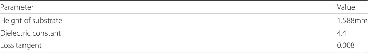
Table 5Some assumed properties of designed antenna
Parameter Value
Height of substrate 1.588mm
Dielectric constant 4.4
Loss tangent 0.008
Results
The GSM1800 frequency band has been considered to test the validity of the proposed algorithms. The objective function has already been mentioned in Eq. (2), and the weight matrixWwas set to [0.3,0.4,0.3]. Some assumed antenna properties have been shown in Table 5.
Optimal antenna for GSM1800
The GSM1800 band is allocated in the frequency band 1805.2∼1879.8 MHz (Downlink), and the three separate optimization technologies have been utilized under two differ-ent antenna size constraints including in antenna size less of than 100 mm as well as an antenna size of less than 150 mm. Additionally, the parameters which are used in the QPSO, CS, and DE algorithms are shown in the Table 6. The proposed algorithms were all implemented in MATLAB and Python, and executed on an Intel coreTM i5 duo PC with 3.10 GHz CPU and 8 GB RAM.
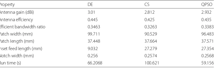
Test case 1: antenna size should be less than 100 mm
For the case that antenna size should be less than 100 mm, the comparison of objective function values against a number of iterations for each of the three algorithms is shown in Fig. 6. The proposed algorithms successfully converge on their minimum solutions. Moreover, the graph illustrates that the DE algorithm performs better than the other two approaches in terms of overall convergence performance. The CS algorithm did not give as effective a convergence ability in comparison to the QPSO and DE approaches in the simulation. The results of simulating the proposed optimal antenna designs obtained from the three bio-inspired algorithms are listed in Table 7.
Table 6Parameters setting of algorithms QPSO, CS, and DE
Algorithms Parameter Value
QPSO α 0.75
Max iterations 500
Population size 20
CS Pa 0.3
Number of nest 20
Max generation 500
β 1
DE Mutation strategy DE/rand-to-best/1
Crossover strategy binomial crossover
F 0.5
CR 0.3
Numbers of population 20
Number of iterations
0 50 100 150 200 250 300 350 400 450 500
Fitness value
0.45 0.5 0.55
0.6 0.65
0.7 0.75
0.8 0.85
0.9
Comparison of convergence of DE,CS, and QPSO
DE CS QPSO
50 100 150 200
0.5 0.55 0.6 0.65 0.7 0.75 0.8 0.85
Fig. 6Comparison of simulation processes of QPSO, CS, and DE with W<100 mm constraint. This figures shows the comparison of the simulation processes of the three methods with the constraint of W<100 mm. The partial drawing at the top right corner shows the fitness function before convergence
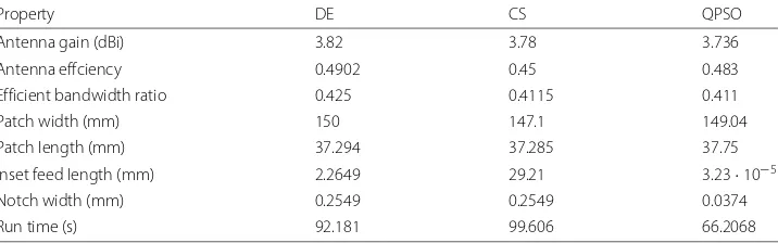
Test case 2: antenna size should be less than 150mm
Similar results are obtained when the antenna size has to be less than 150 mm. The con-vergence characteristics of the three optimization methods are shown in Fig. 7, and it indicates that both the DE and QPSO algorithms are effective, each with a high location accuracy and fast convergence speed. The detailed design parameters for the case 2 where antenna size must be less than 150 mm are shown in Table 8.
Table 7Summary of the properties of designed antenna based on QPSO, CS, and DE for antenna size less than 100 mm
Property DE CS QPSO
Antenna gain (dBi) 3.01 2.812 2.932
Antenna effciency 0.445 0.425 0.435
Efficient bandwidth ratio 0.3463 0.3263 0.3383
Patch width (mm) 99.711 90.529 96.483
Patch length (mm) 37.448 37.664 37.571
Inset feed length (mm) 9.032 27.279 27.354
Notch width (mm) 0.256 0.2574 0.2568
Number of iterations
0 50 100 150 200 250 300 350 400 450 500
Fitness value
0.4 0.45 0.5 0.55 0.6 0.65 0.7 0.75 0.8 0.85
Comparison of convergence of DE,CS, and QPSO
DE CS QPSO
20 40 60 80 100 120 140 160 180 200 0.45
0.5 0.55 0.6 0.65 0.7 0.75 0.8
Fig. 7Comparison of simulation processes of QPSO, CS, and DE with W<150 mm constraint. This figures shows the comparison of the simulation processes of the three methods with the constraint of W<150 mm. The partial drawing at the top right corner shows the fitness function before convergence
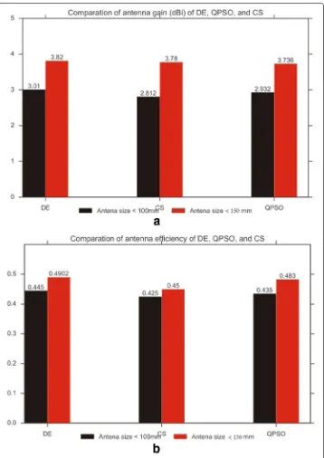
Discussion
On comparing Figs. 8 and 9, it can be seen that the antennas designed based on each of the three bio-inspired algorithms provide significantly improved properties especially for antenna gain (Fig. 8a) and the bandwidth (Fig. 9a) over non-optimised solutions. Amongst the three optimization approaches, the DE solution offers the widest bandwidth, high-est antenna efficiency, and highhigh-est antenna gain, identifying that the DE algorithm has an excellent global search ability. In addition, the QPSO based technology presents its incomparable fast and robust convergence ability as shown in Fig. 9b. With the same number of iteration, the speed of convergence of QPSO is 50.44% faster than the CS, and 39.23% faster the DE algorithm. Results in Fig. 8b indicates that the CS algorithm has the best robustness performance. On contrast, DE is sensitive to the parameters used in
Table 8Comparison between the properties of designed antenna based on QPSO, CS, and DE for antenna size less than 150 mm
Property DE CS QPSO
Antenna gain (dBi) 3.82 3.78 3.736
Antenna effciency 0.4902 0.45 0.483
Efficient bandwidth ratio 0.425 0.4115 0.411
Patch width (mm) 150 147.1 149.04
Patch length (mm) 37.294 37.285 37.75
Inset feed length (mm) 2.2649 29.21 3.23·10−5
Notch width (mm) 0.2549 0.2549 0.0374
Fig. 8Comparison of antenna gain and efficiency of DE, QPSO, and CS. These figures show the comparison of antenna gain and efficiency of the antennas designed by the three methods with the constraint of W
<150 mm and W<100 mm
the simulation. Furthermore, the two tests also show that the increase of antenna size can potentially boost the performance of the antenna. In other words, there is a trade-off between the minimization of antenna size and the antenna performance.
Conclusion
Fig. 9Comparison of of DE, QPSO, and CSof DE, QPSO, and CS. These figures show the effcient antenna bandwidth ratio and running time designed by the three methods with the constraint of W<150 mm and W<100 mm
design approach provides the best solution and hence has the best globally optimum value search ability. This can significantly enhance antenna performance. Moreover, among the three optimization approaches, the CS algorithm has the best robustness. Further-more, the simulations using QPSO based algorithm indicate its superiority displaying a faster convergence speed than DE and CS in the application of solving a complex electromagnetic problem.
Acknowledgements Not applicable.
Funding Not applicable.
Availability of data and materials
All data generated or analyzed during this study are included in this paper and reference list.
Author’s contributions
All of the authors read and approved the final manuscript.
Ethics approval and consent to participate Not applicable.
Consent for publication Not applicable.
Competing interests
The authors declare that they have no competing interests.
Publisher’s Note
Springer Nature remains neutral with regard to jurisdictional claims in published maps and institutional affiliations.
Received: 7 September 2017 Accepted: 30 November 2017
References
1. McHenry MP, Oakley J, Bräunl T. Limitations of testing standards for battery electric vehicles: accessories, energy usage, and range. IET Electr Syst Transp. 2016;6(3):215–21. doi:10.1049/iet-est.2015.0031.
2. Zhou X, Ho CK, Zhang R, Member S. Wireless Power Meets Energy Harvesting : A Joint Energy Allocation Approach in OFDM-Based System. IEEE Trans Wireless Commun. 2016;15(5):3481–491. doi:10.1109/TWC.2016.2522410. 1410.1266.
3. Soyata T, Copeland L, Heinzelman W. RF Energy Harvesting for Embedded Systems: A Survey of Tradeoffs and Methodology. IEEE Circ Syst Mag. 2016;16(1):22–57. doi:10.1109/MCAS.2015.2510198.
4. Visser HJ, Vullers RJM. RF energy harvesting and transport for wireless sensor network applications: Principles and requirements. Proc IEEE. 2013;101(6):1410–1423. doi:10.1109/JPROC.2013.2250891.
5. Zakaria Z, Zainuddin NA, Husain MN, Abidin MZ, Aziz A, Mutalib MA, Othman AR. Current Developments of RF Energy Harvesting System for Wireless Sensor Networks. Adv Inform Sci Service Sci (AISS). 2013;5(June 2013):328–38. doi:10.4156/AISS.vol5.issue11.39.
6. Lu X, Wang P, Niyato D, Kim DI, Han Z. Wireless networks with rf energy harvesting: A contemporary survey. IEEE Commun Surv Tutorials. 2015;17(2):757–89. doi:10.1109/COMST.2014.2368999. arXiv:1406.6470v4.
7. Ghazanfari A, Tabassum H, Hossain E. Ambient RF energy harvesting in ultra-dense small cell networks: Performance and trade-offs. IEEE Wireless Commun. 2016;23(2):38–45. doi:10.1109/MWC.2016.7462483. 8. Piñuela M, Mitcheson PD, Lucyszyn S. Ambient RF energy harvesting in urban and semi-urban environments. IEEE
Trans Microw Theory Tech. 2013;61(7):2715–726. doi:10.1109/TMTT.2013.2262687.
9. Derneryd A. A theoretical investigation of the rectangular microstrip antenna element. IEEE Trans Antennas Propag. 1978;26(4):532–5.
10. Zeng MW, Andrenko AS, Liu X, Tan H-z, Zhu B. Design of Fractal Loop Antenna with Integrated Ground Plane for RF Energy Harvesting. In: 2016 IEEE International Conference on Mathematical Methods in Electromagnetic Theory (MMET). 2016. p. 384–7. http://ieeexplore.ieee.org/document/7543970/.
11. Arrawatia M, Baghini MS, Kumar G. Broadband Bent Triangular Omnidirectional Antenna for RF Energy Harvesting. IEEE Antennas Wireless Propag Letters. 2016;15:36–9. doi:10.1109/LAWP.2015.2427232.
12. Ivanov IK, Rehman MU, Allen B. Printed Microstrip Antenna for Harvesting Energy from Mobile Phone Base Stations. In: Antennas and Propagation (EuCAP), 2016 10th European Conference On. p. 2–6. http://ieeexplore.ieee.org/ document/7481813/.
13. Wen J, Xie D, Liu X, Guo H, Liu C, Yang X. Wideband collar-shaped antenna for RF energy harvesting. In: 2016 Asia-Pacific International Symposium on Electromagnetic Compatibility (APEMC). 2016. p. 253–5.
doi:10.1109/APEMC.2016.7523025.
15. Maher R, Tammam E, Ahmed I. Galal, Hamed HF. Design of A Broadband Planar Antenna for RF Energy Harvesting. In: International Conference on Electrical, Electronics, and Optimization Techniques (ICEEOT). 2016. p. 1808–10. http://ieeexplore.ieee.org/document/7754999/.
16. Li JY, Xu R, Zhou SG, Zhang X, Yang GW. A Wideband High-Gain Cavity-Backed Low-Profile Dipole Antenna. IEEE Trans Antennas Propag. 2016;64(12):1–1. doi:10.1109/TAP.2016.2620607.
17. Simorangkir RBVB, Abbas SM, Esselle KP. A Printed UWB Antenna with Full Ground Plane for WBAN Applications. In: Antenna Technology (iWAT), 2016 International Workshop On. 2016. p. 127–30. http://ieeexplore.ieee.org/ document/7434821/.
18. Mohammed HJ, Abdullah AS, Ali RS, Abd-alhameed RA, Abdulraheem YI, Noras JM. Design of a uniplanar printed triple band- rejected ultra-wideband antenna using particle swarm optimisation and the firefly algorithm. IET Microwaves Antennas Propag. 2016;10:31–7. doi:10.1049/iet-map.2014.0736.
19. Gregory MD, Martin SV, Werner DH. Improved Electromagnetics Optimization. IEEE Antennas Propag Mag. 2015;june. http://ieeexplore.ieee.org/document/7163535/.
20. Gangopadhyaya M, Mukherjee P, Gupta B. Resonant Frequency Optimization of Coaxially Fed Rectangular Microstrip Antenna Using Cuckoo Search Algorithm. 2016 IEEE 7th Annual Information Technology, Electronics and Mobile Communication Conference (IEMCON) 2016. 2016;2:1–4.
21. Manna S, Sharma U, Gangopadhyaya M, Mukherjee P, Gupta B, Ghose R. Comparative Study of Cuckoo Search Optimization and Differential Evolution Algorithm for Design of Microstrip fed Microstrip Patch Antenna. In: 2015 International Conference and Workshop on Computing and Communication (IEMCON). 2015. http://ieeexplore.ieee. org/document/7344439/.
22. Kumar M, Sahoo AB, Sao R, Mangaraj BB. Optimization of rectangular patch antenna at 5GHz using bat search algorithm. Proceedings - 2015 5th International Conference on Communication Systems and Network Technologies, CSNT 2015. 2015;4:68–72. doi:10.1109/CSNT.2015.47.
23. Mishra S, Chattopadya IS, Gangopadhyaya M. A comparative study of DE , PSO and BFO for optimisation of Rectangular Microstrip Patch Antenna with inset feed parameter. In: 2015 International Conference and Workshop on Computing and Communication (IEMCON). 2015. http://ieeexplore.ieee.org/document/7344470/.
24. Carver K, Mink J. Microstrip antenna technology. IEEE Trans Antennas Propag. 1981;29(1):2–24. 25. Dey S, Mittra R. Compact microstrip patch antenna. Microw Opt Technol Lett. 1996;13(1):12–14.
26. Guha D, Biswas M, Antar YM. Microstrip patch antenna with defected ground structure for cross polarization suppression. IEEE Antennas Wireless Propag Letters. 2005;4(1):455–8.
27. Matin MA, Sayeed AI. A design rule for inset-fed rectangular microstrip patch antenna. WSEAS Trans Commun. 2010;9(1):63–72.
28. P PV. B Uckling of R Ectangular P Lates Under. International J Eng Sci Emerging Technol. 2012;3(2):1–12. 29. Yang XS, Deb S. Cuckoo Search via Lévy Flights. In: 2009 World Congress on Nature & Biologically Inspired
Computing (NaBIC 2009). http://ieeexplore.ieee.org/document/5393690/.
30. Arora S, Singh S. A conceptual comparison of firefly algorithm, bat algorithm and cuckoo search. In: 2013 International Conference on Control, Computing, Communication and Materials, ICCCCM. 2013. doi:10.1109/ICCCCM.2013.6648902.
31. Qin AK, Huang VL, Suganthan PN. Differential evolution algorithm with strategy adaptation for global numerical optimization. IEEE Transactions on Evolutionary Computation. 2009. doi:10.1109/TEVC.2008.927706.
32. Das S, Suganthan PN. Differential evolution: A survey of the state-of-the-art. IEEE Transactions on Evolutionary Computation. 2011. doi:10.1109/TEVC.2010.2059031.
33. Brest J, Greiner S, Boškovi B, Mernik M, Zumer V. Self-Adapting Control Parameters in Differential Evolution: A Comparative Study on Numerical Benchmark Problems. IEEE Trans Evol Comput. 2006;10(6).
doi:10.1109/TEVC.2006.872133.
34. Mikki SM, Member S, Kishk AA. Quantum Particle Swarm Optimization for Electromagnetics. 2006;54(10): 2764–2775. http://ieeexplore.ieee.org/document/1707913/.
35. Ho SL, Yang S, Ni G, Huang J. A Quantum-Based Particle Swarm Optimization Algorithm Applied to Inverse Problems. 2013;49(5):2069–2072. http://ieeexplore.ieee.org/document/6514656/.
36. Soman S, Jayadeva, Suri M. Recent trends in neuromorphic engineering. Big Data Analytics. 2016;1(1):15. doi:10.1186/s41044-016-0013-1.
37. Cheng S, Liu B, Ting TO, Qin Q, Shi Y, Huang K. Survey on data science with population-based algorithms. Big Data Analytics. 2016;1(1):3. doi:10.1186/s41044-016-0003-3.
38. Meng K, Wang HG, Dong Z, Member S, Wong KP. Quantum-Inspired Particle Swarm Optimization for Valve-Point Economic Load Dispatch. 2010;25(1):215–222. http://ieeexplore.ieee.org/document/5299292/.
39. Arrawatia M, Baghini M, Kumar G. Differential Microstrip Antenna for RF Energy Harvesting. IEEE Trans Antennas Propag. 2015;PP(99):1–1. doi:10.1109/TAP.2015.2399939.
40. Ghosh S. Design and Testing of RF Energy Harvesting Module in GSM 900 Band using Circularly Polarized Antenna. In: 2015 IEEE International Conference on Research in Computational Intelligence and Communication Networks (ICRCICN). 2015. p. 386–9. http://ieeexplore.ieee.org/document/7434269/.
41. Saghlatoon H, Bjorninen T, Sydanheimo L, Tentzeris MM, Ukkonen L. Inkjet-printed wideband planar monopole antenna on cardboard for RF energy-harvesting applications. IEEE Antennas Wirel Propag Lett. 2015;14:325–8. doi:10.1109/LAWP.2014.2363085.
42. Dadgarpour A, Zarghooni B, Virdee BS, Denidni TA. High-gain end-fire bow-tie antenna using artificial dielectric layers. IET Microw Antennas Propag. 2015;9(12):1254–1259. doi:10.1049/iet-map.2014.0514.
![Table 1 Average RF power density in London [8]](https://thumb-us.123doks.com/thumbv2/123dok_us/301258.1522599/2.595.118.480.634.735/table-average-rf-power-density-london.webp)