metals
Article
Numerical Simulation and Evaluation of Campbell
Running and Gating Systems
Michail Papanikolaou * , Emanuele Pagone, Mark Jolly and Konstantinos Salonitis
Manufacturing Theme, Cranfield University, Cranfield MK430AL, UK; [email protected] (E.P.); [email protected] (M.J.); [email protected] (K.S.)
* Correspondence: [email protected]; Tel.:+44-1234-758-369
Received: 2 December 2019; Accepted: 27 December 2019; Published: 1 January 2020
Abstract: The most common problems encountered in sand casting foundries are related to sand inclusions, air, and oxide films entrainment. These issues can be addressed to a good extent or eliminated by designing proper running systems. The design of a good running system should be based on John Campbell’s “10 casting rules”; it should hinder laminar and turbulent entrainment of the surface film on the liquid, as well as bubble entrainment. These rules have led to the establishment of a group of components such as high and low placed filters (HPF/LPF) and standard gate designs such as the trident gate (TG) and vortex gate (VG) which are incorporated in well-performing running system designs. In this study, the potential of the aforementioned running system designs to eliminate air entrainment and surface defects has been investigated via means of computational fluid dynamics (CFD) simulations. The obtained results suggest that the use of filters significantly enhances the quality of the final cast product; moreover, all of the gating system designs appear to perform better than the basic running system (BRS). Finally, the five in total running and gating system designs have been evaluated with respect to their ability to produce good quality cast products (reduced air entrainment and surface defects) and their sustainability component (runner scrap mass).
Keywords: Campbell running systems; CFD; sustainability
1. Introduction
Casting is one of the oldest and most widely used manufacturing processes. The process consists of two main stages, namely (a) pouring the liquid metal into a mold with the desired shape and (b) solidification. Although this description seems simple, none of the aforementioned sub-processes is trivial and defective cast products can be produced if the casting method is poorly designed. The majority of the defects arise during the filling process due to poorly designed filling systems with surface turbulence and metal front retreating being the most significant entrainment mechanisms [1]. The most common and important types of entrainment defects are oxide bifilms and bubbles. Oxide bifilms are formed when the melt surface folds or two or more surfaces impinge. The double nature and morphology of oxide bifilms has been experimentally observed by Mirak et al. by means of SEM imaging [2]. Oxide bifilms might be submerged or float depending on their relative density. If submerged, bifilms may act as nucleation sites for cracks, shrinkage cavities, or gas bubbles and consequently deteriorate the quality of the final cast product. Bubbles can be formed within the interstices of the oxide bifilms due to gas entrapment. Moreover, hydrogen gas bubbles can be generated upon solidification as the hydrogen dissolved in the melt precipitates out of the solution due to the lower solubility of hydrogen in the solid phase [3]. Bubbles can be categorised as small and large ones depending on their diameter, with a critical value equal to 5 mm [1]. Small bubbles are considered to be the trigger for microporosity formation. Samuel et al. [4] suggested that the spatial distribution of hydrogen bubbles in the solidified Aluminium is interconnected with the presence of
Metals2020,10, 68 2 of 12
oxides. More specifically, the authors showed that in the absence of oxide films hydrogen bubbles float on the top surface of the melt while they get trapped and embedded in the solidified material when oxide films are present in the melt. However, the landscape is different when bubbles surrounded by oxide films are large and buoyant enough to drive themselves to the top surface [5]. In this case, they power their way through partially solidified regions of the material, destroying the dendrite structure, and creating long bifilms, known as “bubble trails”.
The aforementioned defects are most of the time a consequence of a poorly designed running system which induces severe turbulence during filling. In order to address these issues, Campbell [6] thoroughly discussed and advocated some designs and setups for the main components of gravity running systems (pouring basin, sprue, gates, and filters) aiming at the minimisation of entrainment defects in the casting. Starting from the pouring basin, the author emphasised the importance of using an offset step basin instead of a conical one for the following reasons: (a) Bubbles are detained at the step and (b) it allows for proper filling of the sprue. The sprue should be always tapered with a reduction in its cross-sectional area across the vertical downward direction. Moreover, it should have a thin cross section in order to fill quickly and prevent air entrainment and folding. With respect to the gating system, vertical bottom gates may lead to desirable results; it is of utmost importance that the gate velocity should never exceed 1.2 m/s. Two gating system designs have been distinguished by Campbell: (a) The vortex gate (VG) and (b) the trident gate (TG). The vortex gate, initially proposed by Campbell and Puhakka, is capable of redirecting the flow and simultaneously reducing the velocity of the molten metal entering the mold [7]. The vortex gate is frequently combined with a filter placed on top of the vortex cylinder acting as a means of reducing the spin velocity and prohibiting bubbles from entering the mold. The trident gate consists of two filters (one horizontal and one vertical) along with a bubble trap and has been proven to be the most effective gating system ever designed. Finally, one of the most important constituents of a well-designed running system are the filters which have two main functions, namely: The reduction of the metal velocity and the diversion of the flow of bubbles. However, the positioning and design of filters along the running system should be thoughtfully considered as molten metal jets might occur and additional oxides might be formed.
A few decades ago the prevention of casting defects relied solely on experiments, water models, and the experience of foundry engineers. However, the rapid evolution of computing power, as well as the development of new modelling techniques has made the numerical modelling of casting processes feasible via computational fluid dynamics (CFD) simulations. Numerical simulation of casting processes is not a trivial process as it involves a wide range of diverse phenomena such as turbulent flow, various time scales, heat transfer, and phase change. Early research works focused on the modelling of the filling and solidification processes [8], macrosegregation [9], solidification shrinkage [10], and shrinkage-induced microporosity [11]. Contemporary CFD models are capable of predicting oxide film formation [12] and air entrainment [13]. A concrete review of the numerical models implemented for modelling entrainment defects is given in [14]. Nowadays, CFD models are being used in conjunction with design of experiments (DoE) methods [15,16] and optimisation schemes [17,18] in order to eliminate defective locations in castings by altering process parameters such as the pouring temperature or geometrical parameters of the running, feeding, and gating systems.
Metals2020,10, 68 3 of 12
2. Methodology
2.1. Introduction
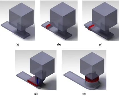
As mentioned in the previous section, five alternative designs were taken from Campbell’s previous work [6] as illustrated in Figure1. For all running systems examined the mold is a cube with dimensions 10×10×10 cm3. This simplistic geometry has been selected as the complexity of the mold
geometry that will not significantly affect the concentration of entrainment defects in the final casting. Moreover, the focus of this work is placed on the defects arising due to the runner and gating systems designs, not on the defects generated after liquid metal enters the mold due to the mold geometry. With the exception of the basic running system (BRS) design which does not contain any filters, the rest of them contain at least one. In the running system designs (LPF and HPF) filters are placed across the length of the runner while in the gating system designs (VG and TG) filters are integrated to the gate.
Metals 2019, 9, x FOR PEER REVIEW 3 of 12
2. Methodology
2.1. Introduction
As mentioned in the previous section, five alternative designs were taken from Campbell’s previous work [6] as illustrated in Figure 1. For all running systems examined the mold is a cube with dimensions 10 × 10 × 10 cm3. This simplistic geometry has been selected as the complexity of the mold geometry that will not significantly affect the concentration of entrainment defects in the final casting. Moreover, the focus of this work is placed on the defects arising due to the runner and gating systems designs, not on the defects generated after liquid metal enters the mold due to the mold geometry. With the exception of the basic running system (BRS) design which does not contain any filters, the rest of them contain at least one. In the running system designs (LPF and HPF) filters are placed across the length of the runner while in the gating system designs (VG and TG) filters are integrated to the gate.
(a) (b) (c)
(d) (e)
Figure 1. Gravity running system designs: (a) Basic running system (BRS), (b) high placed filter (HPF),
(c) low placed filter (LPF), (d) trident gate (TG), and (e) vortex gate (VG).
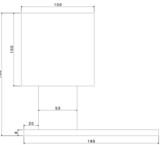
The principal dimensions of the runner and the vertical gate are demonstrated in Figure 2 and have been calculated in order to satisfy the following conditions:
• The filling time should be about equal to 5 s.
• The velocity at the runner should be below 2 m/s.
• The meniscus velocity at the vertical ingate should be less than to 0.8 m/s as suggested by Campbell [6].
Figure 1.Gravity running system designs: (a) Basic running system (BRS), (b) high placed filter (HPF), (c) low placed filter (LPF), (d) trident gate (TG), and (e) vortex gate (VG).
The principal dimensions of the runner and the vertical gate are demonstrated in Figure2and have been calculated in order to satisfy the following conditions:
• The filling time should be about equal to 5 s.
• The velocity at the runner should be below 2 m/s.
• The meniscus velocity at the vertical ingate should be less than to 0.8 m/s as suggested by
Metals2020,10, 68 4 of 12
Metals 2019, 9, x FOR PEER REVIEW 4 of 12
Figure 2.
Principal dimensions of the basic running system (BRS) design. The runner and gate widths
were 53 and 14 mm, respectively. (unit: mm).
2.2. Simulation Setup
The simulation setup is illustrated in Figure 3. In order to eliminate stochasticity emerging from
the metal fall in the sprue and reduce the computational cost, a mass source pouring liquid
aluminium alloy LM25 at 700 °C with a constant velocity equal to 1 m/s (
v
source= 1 m/s) was placed on
the lower half of the runner cross section. The mass source did not cover the whole section of the
runner in order to realistically simulate gravity pouring and allow for backflow and metal folding
across the runner during filling. The mold material was considered to be sand silica. Only half of the
simulation domain was simulated by exploiting symmetry boundary conditions in order to reduce
the computational cost [17]. The only exception was the VG design which is asymmetric, so in this
case the whole domain was simulated. The simulation was terminated automatically when the mold
was completely filled (fill fraction was equal to 1).
Figure 3.
Simulation setup.
A hexahedral mesh with a cell size equal to 1.5 mm was utilised for solving the mass,
momentum, and energy conservation equations. The cell size was selected so as to ensure that at least
three cells expand across the thinnest cross section of the casting located at the runner (see Figure 2).
Figure 2.Principal dimensions of the basic running system (BRS) design. The runner and gate widths were 53 and 14 mm, respectively. (unit: mm).
2.2. Simulation Setup
The simulation setup is illustrated in Figure3. In order to eliminate stochasticity emerging from the metal fall in the sprue and reduce the computational cost, a mass source pouring liquid aluminium alloy LM25 at 700◦
C with a constant velocity equal to 1 m/s (vsource=1 m/s) was placed on the lower
half of the runner cross section. The mass source did not cover the whole section of the runner in order to realistically simulate gravity pouring and allow for backflow and metal folding across the runner during filling. The mold material was considered to be sand silica. Only half of the simulation domain was simulated by exploiting symmetry boundary conditions in order to reduce the computational cost [17]. The only exception was the VG design which is asymmetric, so in this case the whole domain was simulated. The simulation was terminated automatically when the mold was completely filled (fill fraction was equal to 1).
Metals 2019, 9, x FOR PEER REVIEW 4 of 12
Figure 2. Principal dimensions of the basic running system (BRS) design. The runner and gate widths were 53 and 14 mm, respectively. (unit: mm).
2.2. Simulation Setup
The simulation setup is illustrated in Figure 3. In order to eliminate stochasticity emerging from the metal fall in the sprue and reduce the computational cost, a mass source pouring liquid aluminium alloy LM25 at 700 °C with a constant velocity equal to 1 m/s (vsource = 1 m/s) was placed on the lower half of the runner cross section. The mass source did not cover the whole section of the runner in order to realistically simulate gravity pouring and allow for backflow and metal folding across the runner during filling. The mold material was considered to be sand silica. Only half of the simulation domain was simulated by exploiting symmetry boundary conditions in order to reduce the computational cost [17]. The only exception was the VG design which is asymmetric, so in this case the whole domain was simulated. The simulation was terminated automatically when the mold was completely filled (fill fraction was equal to 1).
Figure 3. Simulation setup.
A hexahedral mesh with a cell size equal to 1.5 mm was utilised for solving the mass, momentum, and energy conservation equations. The cell size was selected so as to ensure that at least three cells expand across the thinnest cross section of the casting located at the runner (see Figure 2).
Metals2020,10, 68 5 of 12
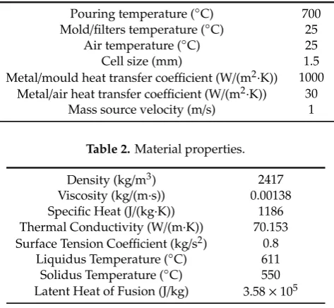
A hexahedral mesh with a cell size equal to 1.5 mm was utilised for solving the mass, momentum, and energy conservation equations. The cell size was selected so as to ensure that at least three cells expand across the thinnest cross section of the casting located at the runner (see Figure2). The total number of cells ranged between 150,000 and 300,000 cells depending on the running system design under examination. The constructed mesh was conformed to the open volume with an overlap length equal to 10 mm in order to minimise the computational cost. Symmetry boundary conditions were applied to all of the directions. In the present CFD model which accounted for surface tension, the renormalized group model (RNG) was employed for modelling turbulence [20]. The commercial CFD software FLOW-3D®(Version 12.0, Flow Science, Santa Fe, NM, USA) was utilised to complete this study [21]. The simulation parameters and material properties used are summarised in Tables1and2, respectively.
Table 1.Simulation parameters.
Pouring temperature (◦C) 700 Mold/filters temperature (◦C) 25
Air temperature (◦C) 25 Cell size (mm) 1.5 Metal/mould heat transfer coefficient (W/(m2·K)) 1000
Metal/air heat transfer coefficient (W/(m2·K)) 30
Mass source velocity (m/s) 1
Table 2.Material properties.
Density (kg/m3) 2417 Viscosity (kg/(m·s)) 0.00138
Specific Heat (J/(kg·K)) 1186
Thermal Conductivity (W/(m·K)) 70.153
Surface Tension Coefficient (kg/s2) 0.8 Liquidus Temperature (◦C) 611 Solidus Temperature (◦C) 550 Latent Heat of Fusion (J/kg) 3.58×10⁵
Air entrainment and surface defect concentration were calculated according to the software-integrated models ([13] and [22], respectively). More specifically, the basic idea behind the air entrainment model is that turbulent eddies at the free surface raise fluid elements above the free surface; this phenomenon might lead to air entrainment in the body of the fluid. Air entrainment is quantified using a dimensionless scalar (Entrained air volume fraction) whose value is indicative of the fractional volume of air entrained into a fluid element. The employed defect tracking is a cumulative scalar technique, assuming that oxide defects accumulate at the fluid’s free surface at a constant rate; this oxide accumulation is described by a scalar parameter (defect mass). This scalar is diffused and advected with the bulk fluid motion. The final distribution of this scalar across the simulation domain is indicative of the defective locations.
3. Results
3.1. Running System Design
Metals2020,10, 68 6 of 12
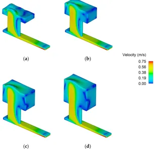
mass source as elaborated in the previous section. It can be observed that the velocity magnitude in the lower part of the runner cross section at the vicinity of mass source is higher than 0.75 m/s (vsource=1 m/s) and the flow is decelerated across the runner while approaching the ingate.
Metals 2019, 9, x FOR PEER REVIEW 6 of 12
than 0.75 m/s (vsource = 1 m/s) and the flow is decelerated across the runner while approaching the ingate.
(a) (b)
(c) (d)
Figure 4. Basic running system (BRS) velocity profiles at (a) 1.5, (b) 2.5, (c) 3.5, and (d) 4.5 s.
The presence of filters does not result to significantly more uniform filling of the mold. Their importance however lies on the more uniform priming of the runner, as illustrated in Figure 5b. This is in agreement with Campbell’s observations [6] who suggested that one of the main functions of filters should be reducing the velocity of the metal stream. The absence of filters results in backflow as illustrated in Figure 5a. Increased air entrainment due to surface turbulence is an immediate consequence of the non-uniform filling of the runner as illustrated in Figure 6. Similar results have been obtained for the surface defect concentration as it is dependent on the fluid velocity and time.
(a) (b)
Figure 5. Velocity profiles at t = 0.4 s for the (a) basic running system (BRS) and (b) low placed filter (LPF) designs.
Figure 4.Basic running system (BRS) velocity profiles at (a) 1.5, (b) 2.5, (c) 3.5, and (d) 4.5 s.
The presence of filters does not result to significantly more uniform filling of the mold. Their importance however lies on the more uniform priming of the runner, as illustrated in Figure5b. This is in agreement with Campbell’s observations [6] who suggested that one of the main functions of filters should be reducing the velocity of the metal stream. The absence of filters results in backflow as illustrated in Figure5a. Increased air entrainment due to surface turbulence is an immediate consequence of the non-uniform filling of the runner as illustrated in Figure6. Similar results have been obtained for the surface defect concentration as it is dependent on the fluid velocity and time.
Metals 2019, 9, x FOR PEER REVIEW 6 of 12
than 0.75 m/s (vsource = 1 m/s) and the flow is decelerated across the runner while approaching the ingate.
(a) (b)
(c) (d)
Figure 4. Basic running system (BRS) velocity profiles at (a) 1.5, (b) 2.5, (c) 3.5, and (d) 4.5 s.
The presence of filters does not result to significantly more uniform filling of the mold. Their importance however lies on the more uniform priming of the runner, as illustrated in Figure 5b. This is in agreement with Campbell’s observations [6] who suggested that one of the main functions of filters should be reducing the velocity of the metal stream. The absence of filters results in backflow as illustrated in Figure 5a. Increased air entrainment due to surface turbulence is an immediate consequence of the non-uniform filling of the runner as illustrated in Figure 6. Similar results have been obtained for the surface defect concentration as it is dependent on the fluid velocity and time.
(a) (b)
Figure 5. Velocity profiles at t = 0.4 s for the (a) basic running system (BRS) and (b) low placed filter (LPF) designs.
Metals2020,10, 68 7 of 12
Metals 2019, 9, x FOR PEER REVIEW 7 of 12
(a) (b)
Figure 6. Entrained air volume fraction profiles at t = 2 s for the (a) basic running system (BRS) and
(b) low placed filter (LPF) designs.
Figures 5 and 6 provide a visual inspection of the flow field and air entrainment for the BRS and LPF designs. However, in order to have a concrete evaluation of the total entrained air and surface defect concentration, their values were estimated at the end of the filling process for the cells lying in the mold region; more specifically, the average value was estimated for the three cases under examination (BRS, LPH, and HPF). As illustrated in Figure 7a,b the use of filters is beneficial as it results in less entrained air and surface defects in the final cast product. The LPF design appears to be a slightly better performer compared to the HPF. This is in agreement with Campbell’s observations, reporting that high placed filters carry the danger of jetting metal from their exit face. On the other hand, in low placed filter installations jetting is suppressed and better quality metal is delivered to the casting [6]. Finally, the additional scrap mass added due to the installation of filters on the runner is negligible; filters do not deteriorate the sustainability of the process.
(a) (b)
Figure 7. (a) Average entrained air volume fraction and (b) average surface defect concentration for the basic running system (BRS), high placed filter (HPF) and low placed filter (LPF) designs.
3.2. Gating System Design
As mentioned in the Introduction Section the performance of three gating systems, namely vertical gate (BRS), trident gate (TG), and vortex gate (VG) is going to be discussed in this section. As illustrated in Figure 8, both of the TG and VG designs deliver more tranquil filling of the mold compared to the BRS design (Figure 4), with the VG design appearing to be the best performer. At
Figure 6.Entrained air volume fraction profiles att=2 s for the (a) basic running system (BRS) and (b) low placed filter (LPF) designs.
Figures5and6provide a visual inspection of the flow field and air entrainment for the BRS and LPF designs. However, in order to have a concrete evaluation of the total entrained air and surface defect concentration, their values were estimated at the end of the filling process for the cells lying in the mold region; more specifically, the average value was estimated for the three cases under examination (BRS, LPH, and HPF). As illustrated in Figure7a,b the use of filters is beneficial as it results in less entrained air and surface defects in the final cast product. The LPF design appears to be a slightly better performer compared to the HPF. This is in agreement with Campbell’s observations, reporting that high placed filters carry the danger of jetting metal from their exit face. On the other hand, in low placed filter installations jetting is suppressed and better quality metal is delivered to the casting [6]. Finally, the additional scrap mass added due to the installation of filters on the runner is negligible; filters do not deteriorate the sustainability of the process.
Metals 2019, 9, x FOR PEER REVIEW 7 of 12
(a) (b)
Figure 6. Entrained air volume fraction profiles at t = 2 s for the (a) basic running system (BRS) and
(b) low placed filter (LPF) designs.
Figures 5 and 6 provide a visual inspection of the flow field and air entrainment for the BRS and LPF designs. However, in order to have a concrete evaluation of the total entrained air and surface defect concentration, their values were estimated at the end of the filling process for the cells lying in the mold region; more specifically, the average value was estimated for the three cases under examination (BRS, LPH, and HPF). As illustrated in Figure 7a,b the use of filters is beneficial as it results in less entrained air and surface defects in the final cast product. The LPF design appears to be a slightly better performer compared to the HPF. This is in agreement with Campbell’s observations, reporting that high placed filters carry the danger of jetting metal from their exit face. On the other hand, in low placed filter installations jetting is suppressed and better quality metal is delivered to the casting [6]. Finally, the additional scrap mass added due to the installation of filters on the runner is negligible; filters do not deteriorate the sustainability of the process.
(a) (b)
Figure 7. (a) Average entrained air volume fraction and (b) average surface defect concentration for the basic running system (BRS), high placed filter (HPF) and low placed filter (LPF) designs.
3.2. Gating System Design
As mentioned in the Introduction Section the performance of three gating systems, namely vertical gate (BRS), trident gate (TG), and vortex gate (VG) is going to be discussed in this section. As illustrated in Figure 8, both of the TG and VG designs deliver more tranquil filling of the mold compared to the BRS design (Figure 4), with the VG design appearing to be the best performer. At
Figure 7.(a) Average entrained air volume fraction and (b) average surface defect concentration for the basic running system (BRS), high placed filter (HPF) and low placed filter (LPF) designs.
3.2. Gating System Design
Metals2020,10, 68 8 of 12
clarified that the ingate cross section area dimensions are identical for all the cases under examination. It is clear in both cases that filters slow down the melt. As reported by Campbell [6], in the VG case “the filter acts to reduce the spin speed immediately before the metal enters the casting, otherwise
metal tends to spin out, spraying sideways into the mold”.
Metals 2019, 9, x FOR PEER REVIEW 8 of 12
this point it should be clarified that the ingate cross section area dimensions are identical for all the cases under examination. It is clear in both cases that filters slow down the melt. As reported by Campbell [6], in the VG case “the filter acts to reduce the spin speed immediately before the metal enters the casting, otherwise metal tends to spin out, spraying sideways into the mold”.
(a) (b)
Figure 8. Velocity profiles for the (a) trident gate (TG) and (b) vortex gate (VG) systems.
Although filling is more tranquil in the TV and VG cases, air entrainment is still present in the casting as demonstrated in Figure 9. By observing Figure 9a, it is evident that in the TG case, when the melt enters the gate, air is entrained due to the change of the flow direction as in the BRS case (Figure 6). A portion of the entrained air is trapped in the bubble trap; however, some part of it escapes and enters the mold. Moreover, entrained air can be generated at the corner of the ingate entrance area (change of flow direction). Figure 9b is a visual representation of what has been previously reported by Campbell in [6]: “In the case of the Vortex Gate bubbles arriving at the gate are centrifuged into the center of the rising metal, and are trapped under the center of the filter, from where they cannot escape. However, as more bubbles arrive, growing the central bubble under the filter, its buoyancy and drag forces combine, eventually forcing the bubble through. Several large bubbles may defeat the filter in this way.”
(a) (b)
Figure 9. Entrained air volume fraction profiles the (a) trident gate (TG) and (b) vortex gate (VG) designs.
Similarly to the previous section, a quantitative estimation of the average entrained air volume fraction and surface defect concentration located at the area of the mold has been given in Figure 10.
Figure 8.Velocity profiles for the (a) trident gate (TG) and (b) vortex gate (VG) systems.
Although filling is more tranquil in the TV and VG cases, air entrainment is still present in the casting as demonstrated in Figure9. By observing Figure9a, it is evident that in the TG case, when the melt enters the gate, air is entrained due to the change of the flow direction as in the BRS case (Figure6). A portion of the entrained air is trapped in the bubble trap; however, some part of it escapes and enters the mold. Moreover, entrained air can be generated at the corner of the ingate entrance area (change of flow direction). Figure9b is a visual representation of what has been previously reported by Campbell in [6]: “In the case of the Vortex Gate bubbles arriving at the gate are centrifuged into the center of the rising metal, and are trapped under the center of the filter, from where they cannot escape. However, as more bubbles arrive, growing the central bubble under the filter, its buoyancy and drag forces combine, eventually forcing the bubble through. Several large bubbles may defeat the filter in this way.”
Metals 2019, 9, x FOR PEER REVIEW 8 of 12
this point it should be clarified that the ingate cross section area dimensions are identical for all the cases under examination. It is clear in both cases that filters slow down the melt. As reported by Campbell [6], in the VG case “the filter acts to reduce the spin speed immediately before the metal enters the casting, otherwise metal tends to spin out, spraying sideways into the mold”.
(a) (b)
Figure 8. Velocity profiles for the (a) trident gate (TG) and (b) vortex gate (VG) systems.
Although filling is more tranquil in the TV and VG cases, air entrainment is still present in the casting as demonstrated in Figure 9. By observing Figure 9a, it is evident that in the TG case, when the melt enters the gate, air is entrained due to the change of the flow direction as in the BRS case (Figure 6). A portion of the entrained air is trapped in the bubble trap; however, some part of it escapes and enters the mold. Moreover, entrained air can be generated at the corner of the ingate entrance area (change of flow direction). Figure 9b is a visual representation of what has been previously reported by Campbell in [6]: “In the case of the Vortex Gate bubbles arriving at the gate are centrifuged into the center of the rising metal, and are trapped under the center of the filter, from where they cannot escape. However, as more bubbles arrive, growing the central bubble under the filter, its buoyancy and drag forces combine, eventually forcing the bubble through. Several large bubbles may defeat the filter in this way.”
(a) (b)
Figure 9. Entrained air volume fraction profiles the (a) trident gate (TG) and (b) vortex gate (VG) designs.
Similarly to the previous section, a quantitative estimation of the average entrained air volume fraction and surface defect concentration located at the area of the mold has been given in Figure 10.
Metals2020,10, 68 9 of 12
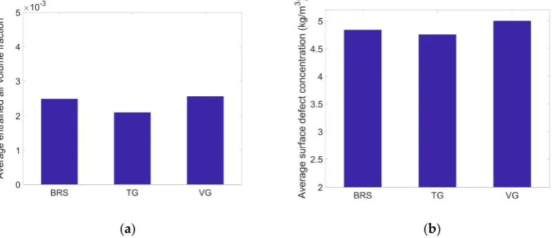
Similarly to the previous section, a quantitative estimation of the average entrained air volume fraction and surface defect concentration located at the area of the mold has been given in Figure10. With regard to both air entrainment and surface defect concentration the trident gate is the best performer. This is in accordance to Campbell’s allegations [6] who argued that the trident gate has been proven to be the best gating system so far for controlling metal velocity and quality. On the other hand, the vortex gate appears to have the poorest performance among the three alternative designs.
Metals 2019, 9, x FOR PEER REVIEW 9 of 12
With regard to both air entrainment and surface defect concentration the trident gate is the best performer. This is in accordance to Campbell’s allegations [6] who argued that the trident gate has been proven to be the best gating system so far for controlling metal velocity and quality. On the other hand, the vortex gate appears to have the poorest performance among the three alternative designs.
(a) (b)
Figure 10. (a) Average entrained air volume fraction and (b) average surface defect concentration for the basic running system (BRS), trident gate (TG) and vortex gate (VG) designs.
The reason behind the poor performance of the vortex gate in this particular occasion is related to the fact that entrained air makes its way through the filter into the mold. According to Campbell, the vortex gate works better when dealing with high velocity metal [6]. In order to test this allegation, the simulations were repeated with an increased mass source velocity equal to 1.5 m/s. The results are illustrated in Figure 11. Compared to the bar charts of Figure 10, it is evident that the average entrained air volume fraction is higher; this is due to the increased turbulence resulting from the higher mass source velocity. On the other hand, the average surface defect concentration is lower as expected, because of the lower filling time. However, when comparing the performance of the gating designs between them, the landscape is different this time. Although the trident gate remains the ultimate solution among the three alternatives, the vortex gate appears to be a better performer than the basic running system. This result supports the allegation of Campbell stating that the vortex gate performs better when the metal velocity is high.
(a) (b)
Figure 11. (a) Average entrained air volume fraction and (b) average surface defect concentration for the basic running system (BRS), trident gate (TG) and vortex gate (VG) designs with a mass source velocity of 1.5 m/s.
Figure 10.(a) Average entrained air volume fraction and (b) average surface defect concentration for the basic running system (BRS), trident gate (TG) and vortex gate (VG) designs.
The reason behind the poor performance of the vortex gate in this particular occasion is related to the fact that entrained air makes its way through the filter into the mold. According to Campbell, the vortex gate works better when dealing with high velocity metal [6]. In order to test this allegation, the simulations were repeated with an increased mass source velocity equal to 1.5 m/s. The results are illustrated in Figure11. Compared to the bar charts of Figure10, it is evident that the average entrained air volume fraction is higher; this is due to the increased turbulence resulting from the higher mass source velocity. On the other hand, the average surface defect concentration is lower as expected, because of the lower filling time. However, when comparing the performance of the gating designs between them, the landscape is different this time. Although the trident gate remains the ultimate solution among the three alternatives, the vortex gate appears to be a better performer than the basic running system. This result supports the allegation of Campbell stating that the vortex gate performs better when the metal velocity is high.
Metals2020,10, 68 10 of 12
Metals 2019, 9, x FOR PEER REVIEW 9 of 12
With regard to both air entrainment and surface defect concentration the trident gate is the best performer. This is in accordance to Campbell’s allegations [6] who argued that the trident gate has been proven to be the best gating system so far for controlling metal velocity and quality. On the other hand, the vortex gate appears to have the poorest performance among the three alternative designs.
(a) (b)
Figure 10. (a) Average entrained air volume fraction and (b) average surface defect concentration for the basic running system (BRS), trident gate (TG) and vortex gate (VG) designs.
The reason behind the poor performance of the vortex gate in this particular occasion is related to the fact that entrained air makes its way through the filter into the mold. According to Campbell, the vortex gate works better when dealing with high velocity metal [6]. In order to test this allegation, the simulations were repeated with an increased mass source velocity equal to 1.5 m/s. The results are illustrated in Figure 11. Compared to the bar charts of Figure 10, it is evident that the average entrained air volume fraction is higher; this is due to the increased turbulence resulting from the higher mass source velocity. On the other hand, the average surface defect concentration is lower as expected, because of the lower filling time. However, when comparing the performance of the gating designs between them, the landscape is different this time. Although the trident gate remains the ultimate solution among the three alternatives, the vortex gate appears to be a better performer than the basic running system. This result supports the allegation of Campbell stating that the vortex gate performs better when the metal velocity is high.
(a) (b)
Figure 11. (a) Average entrained air volume fraction and (b) average surface defect concentration for the basic running system (BRS), trident gate (TG) and vortex gate (VG) designs with a mass source velocity of 1.5 m/s.
Figure 11.(a) Average entrained air volume fraction and (b) average surface defect concentration for the basic running system (BRS), trident gate (TG) and vortex gate (VG) designs with a mass source velocity of 1.5 m/s.
Metals 2019, 9, x FOR PEER REVIEW 10 of 12
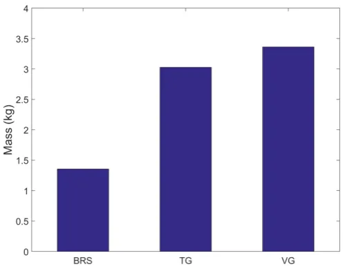
As discussed in the previous paragraphs, the TG and VG designs can deliver better quality castings compared to the BRS design under specific conditions. However, there is an additional penalty associated with enhanced quality; the yield decreases as the total mass of the metal increases (see Figure 12). Moreover, additional energy is required for recycling the scrap mass. The total casting mass in the TG and VG cases is almost double the mass of the BRS design. It is obvious that this fraction would be much lower if the cast product was larger but it would still make a difference. It is therefore evident that there is still room for optimisation of the TG and VG gating system designs with respect to the sustainability component of the process.
Figure 12. Total casting mass.
4. Conclusions and Future Work
In this study, CFD simulations have been performed to investigate and validate the potential of running and gating systems proposed by Campbell [6] to deliver enhanced quality castings. The obtained results are in agreement with the experimental observations of Campbell. The main conclusions drawn are summarised below:
• As pointed out by Campbell it is of utmost importance to regulate the velocity of the metal in the runner. The use of filters is crucial for achieving this goal as they contribute to the faster priming of the runner. This in turn leads to reduced air entrainment and surface defects concentration in the final cast product. Low placed filters lead to better results as they are more efficient in protecting the back of the filter with liquid metal.
• With regard to the gating system designs, both the vortex and trident gates contribute to more tranquil filling of the mold compared to the vertical gates (BRS).
• The trident gate delivers the best results with respect to the minimisation of defects in the final casting. Air entrainment is significantly reduced but not eliminated.
• The vortex gate yields inferior results compared to the vertical gate when the filling velocity is low. However, this tendency is inversed for higher filling speeds. This is agreement with Campbell’s observation that vortex gates work better for high velocity metal.
• Although the trident and vortex gates might deliver superior quality castings compared to the vertical gate there is a cost for this: Increased scrap mass and lower yield.
Despite the fact that the potential of the trident and vortex gates to deliver superior quality castings has been verified via means of numerical simulations, it is evident that there is still room for the optimisation of the aforementioned gate designs with respect to their yield performance and energy efficiency. Future research should be directed towards the geometrical optimisation of these two designs in order to further enhance their performance with respect to both casting quality and energy efficiency.
Figure 12.Total casting mass.
4. Conclusions and Future Work
In this study, CFD simulations have been performed to investigate and validate the potential of running and gating systems proposed by Campbell [6] to deliver enhanced quality castings. The obtained results are in agreement with the experimental observations of Campbell. The main conclusions drawn are summarised below:
• As pointed out by Campbell it is of utmost importance to regulate the velocity of the metal in the
runner. The use of filters is crucial for achieving this goal as they contribute to the faster priming of the runner. This in turn leads to reduced air entrainment and surface defects concentration in the final cast product. Low placed filters lead to better results as they are more efficient in protecting the back of the filter with liquid metal.
• With regard to the gating system designs, both the vortex and trident gates contribute to more
tranquil filling of the mold compared to the vertical gates (BRS).
• The trident gate delivers the best results with respect to the minimisation of defects in the final
Metals2020,10, 68 11 of 12
• The vortex gate yields inferior results compared to the vertical gate when the filling velocity is low.
However, this tendency is inversed for higher filling speeds. This is agreement with Campbell’s observation that vortex gates work better for high velocity metal.
• Although the trident and vortex gates might deliver superior quality castings compared to the
vertical gate there is a cost for this: Increased scrap mass and lower yield.
Despite the fact that the potential of the trident and vortex gates to deliver superior quality castings has been verified via means of numerical simulations, it is evident that there is still room for the optimisation of the aforementioned gate designs with respect to their yield performance and energy efficiency. Future research should be directed towards the geometrical optimisation of these two designs in order to further enhance their performance with respect to both casting quality and energy efficiency.
Author Contributions: Conceptualization, M.P. and M.J.; Methodology, M.P. and E.P.; Software M.P. and E.P.; Validation, M.P.; Formal analysis, M.P.; Investigation, M.P.; Resources, K.S. and M.J.; Data curation, M.P.; Writing—original draft preparation, M.P.; Writing—review and editing, M.P., E.P., K.S., and M.J.; Visualization, M.P.; Supervision, K.S. and M.J.; Project administration, M.P., K.S., and M.J.; Funding acquisition, K.S. and M.J. All authors have read and agreed to the published version of the manuscript.
Funding: This research was funded by the UK EPSRC project “Energy Resilient Manufacturing 2: Small is Beautiful Phase 2 (SIB2)” under grant EP/P012272/1.
Acknowledgments:The authors would like to thank Chengcheng Lyu for her work during her MSc thesis.
Conflicts of Interest:The authors declare no conflict of interest.
References
1. Campbell, J. Complete casting handbook: Metal casting processes, techniques and design.Metall. Tech. Des. 2011,2, 244.
2. Mirak, A.R.; Divandari, M.; Boutorabi, S.M.A.; Campbell, J. Oxide film characteristics of AZ91 magnesium alloy in casting conditions.Int. J. Cast Met. Res.2007,20, 215–220. [CrossRef]
3. Tian, C.; Law, J.; Van der Touw, J.; Murray, M.; Yao, J.Y.; Graham, D.; St. John, D. Effect of melt cleanliness on the formation of porosity defects in automotive aluminium high pressure die castings.J. Mater. Process. Technol. 2002,122, 82–93. [CrossRef]
4. Samuel, A.M.; Samuel, F.H. The reduced pressure test as a measuring.Metall. Trans. A1993,24, 1857–1868. [CrossRef]
5. Campbell, J. Entrainment defects.Mater. Sci. Technol.2006,22, 127–145. [CrossRef] 6. Campbell, J.MINI CASTING HANDBOOK; Aspect Design: Malvern, UK, 2018.
7. Puhakka, R. Advanced Methoding Concepts for the Gravity Casting of Steel Alloys. In Proceedings of the TMS Annual Conference, 4th Shape Casting Symposium, San Diego, CA, USA, 27 February–3 March 2011; pp. 241–248.
8. Barkhudarov, M.; Hirt, C. Casting simulation: Mold filling and solidification–Benchmark calculations using FLOW-3D®.Model. Cast. Weld. Adv. Solidif. Process.1995,12, 935–946.
9. Haug, E.; Mo, A.; Thevik, H.J. Macrosegregation near a cast surface caused by exudation and solidification shrinkage.Int. J. Heat Mass Transf.1995,38, 1553–1563. [CrossRef]
10. Trovant, M.; Argyropoulos, S.A. Mathematical modeling and experimental measurements of shrinkage in the casting of metals.Can. Metall. Q.1996,35, 75–84. [CrossRef]
11. Combeau, H.; Carpentier, D.; Lacaze, J.; Lesoult, G. Modelling of microporosity formation in aluminium alloys castings.Mater. Sci. Eng. A1993,173, 155–159. [CrossRef]
12. Reilly, C.; Green, N.R.; Jolly, M.R.; Gebelin, J.-C. The modelling of oxide film entrainment in casting systems using computational modelling.Appl. Math. Model.2013,37, 8451–8466. [CrossRef]
13. Hirt, C.W.Modeling Turbulent Entrainment of Air at a Free Surface; Flow Science Report 01-12; Flow Science: Santa Fe, NM, USA, 2012.
Metals2020,10, 68 12 of 12
15. Dabade, U.A.; Bhedasgaonkar, R.C. Casting defect analysis using design of experiments (DoE) and computer aided casting simulation technique.Procedia CIRP2013,7, 616–621. [CrossRef]
16. Sun, Z.; Hu, H.; Chen, X. Numerical optimization of gating system parameters for a magnesium alloy casting with multiple performance characteristics.J. Mater. Process. Technol.2008,199, 256–264. [CrossRef] 17. Papanikolaou, M.; Pagone, E.; Georgarakis, K.; Rogers, K.; Jolly, M.; Salonitis, K. Design optimisation of the
feeding system of a novel counter-gravity casting process.Metals2018,8, 817. [CrossRef]
18. Krimpenis, A.; Benardos, P.G.; Vosniakos, G.-C.; Koukouvitaki, A. Simulation-based selection of optimum pressure die-casting process parameters using neural nets and genetic algorithms.Int. J. Adv. Manuf. Technol. 2006,27, 509–517. [CrossRef]
19. Lyu, C.; Papanikolaou, M.; Jolly, M. Numerical process modelling and simulation of campbell running systems designs. InShape Casting; Springer: Cham, Switzerland, 2019; pp. 53–64.
20. Tota, P.V. Turbulent Flow Over a Backward-Facing Step Using the RNG k-εModel.Flow Sci.2009,1, 1–15. 21. FLOW-3D®; Version 12.0; Flow Science, Inc.: Santa Fe, NM, USA, 2019.
22. Hirt, C.W.Modeling Surface Tension; Flow Science Report 01-14; Flow Science: Santa Fe, NM, USA, 2014.