R e d u c tio n
by
Patrick John Wright
A thesis submitted to the University of London
for the Degree of Doctor of Philosophy
Department of Electronic and Electrical Engineering
University College London
ProQuest Number: 10106816
All rights reserved
INFORMATION TO ALL USERS
The quality of this reproduction is dependent upon the quality of the copy submitted.
In the unlikely event that the author did not send a complete manuscript and there are missing pages, these will be noted. Also, if material had to be removed,
a note will indicate the deletion.
uest.
ProQuest 10106816
Published by ProQuest LLC(2016). Copyright of the Dissertation is held by the Author.
All rights reserved.
This work is protected against unauthorized copying under Title 17, United States Code. Microform Edition © ProQuest LLC.
ProQuest LLC
789 East Eisenhower Parkway P.O. Box 1346
A b stract.
Parallel processing offers a route to more powerful computation, but many problems have arisen on the path to the realisation of practical implementations of such architectures. One of the most important stumbling blocks in preventing parallel processors reaching widespread conunercial fruition, is the problem of programming. Standard procedural languages, even when modified, offer an inadequate programming paradigm for such machines. A promising technique, combining the power of parallel processing with the software advantages of functional programming, is graph reduction.
In the development of reduction architectures designed for functional programming, one of the most important implementation issues, affecting operational efficiency, is that of garbage collection. Of the three main methods of collection available, the most promising appears to be reference counting. This, however, suffers from a number of drawbacks: it involves a large memory overhead to support the scheme, it will not intrinsically deal with self-referencing (cyclic) structures and it is not real time in nature.
The thesis starts with a short historical perspective on parallel processing, briefly presenting some of the major milestones in parallel architecture research. The discussion continues by introducing functional languages and the problems raised by garbage collection. The major garbage collection techniques are discussed and the reasons for exploring reference counting are explained.
The first aspect of reference counting collection to be addressed is the memory overhead. An architecture for alleviating this problem is presented, based upon limited-width reference count fields. The chapter concludes with analysis of the new techniques and contrasts the worst case performance against the standard methods.
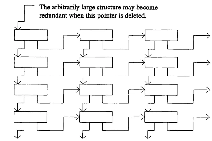
A short chapter then introduces real time systems, with particular reference to functional programming and the attempts to make standard garbage collection techniques suitable for real time systems. The discussion continues with a novel technique for the collection of large redundant data structures in real time. A system is then discussed for implementing the collection of redundant cyclic structures, within the graph, in real time. As each aspect of the technique is explored, algorithms are presented.
The thesis continues by presenting a worse case temporal analysis of the major services offered by the collector to a graph mutator.
A formal verification of the basic real time collector, using the MALvem Program Analysis Suite (MALPAS) is presented.
A simulator for the system has been written, which was used to test the techniques developed and to ascertain if the theoretical predictions are valid. This software implementation of the collector is described and some of the results obtained are presented and discussed. The performance of the new reference counting techniques are compared with an implementation of Baker's algorithm.
The thesis concludes with a critical appraisal of the work carried out, and a discussion of how the research could progress, to realise a practical collector in a viable commercial parallel graph reduction machine.
-3-A ck n o w led g em en ts.
The author wishes to express his gratitude to Prof. R.J. Offen for all his support and guidance during the course of this research. Thanks are also due to Dr. O.J. Davies, for his help in the early stages of the project.
The financial support of Racal Research Ltd. is gratefully acknowledged, as is the help and guidance from Mr. Eric Harper and Dr. Tim Burnett of Racal.
Thanks are due to the Defence Research Agency, Malvern (CADI Division) and also in particular to Dr. Brian Bramson for his invaluable expert advice in the use of MALPAS.
Finally, the author would like to thank his colleagues. Dr. Paul Houselander and Vish Patel for many long and useful discussions.
Published with the permission o f the
Controller o f Her Britannic Majesty's Stationary Office
C o n ten ts.
Abstract. 3
Acknowledgements. 5
List of Figures. 12
List of Tables. 14
Chapter 1. Introduction to Parallel Processing. 15
1.1 Background. 15
1.2 Parallel Architectures. 15
1.3 The Software Problem. 16
1.3.1 Imperative Languages. 17
1.3.2 Alternatives to Imperative Languages. 18
1.3.3 Logic Languages. 18
1.3.4 Data Flow Languages. 19
1.3.5 Functional Languages. 19
1.4 Conclusions. 19
Chapter 2. Functional Languages. 20
2.1 Some Major Features of a Functional Style. 20
2.1.1 Referential Transparency and Parallel Processing. 20
2.2 Architectures for Supporting Functional Languages, 21
2.2.1 Graph Reduction, 21
2.2.2 Alternative Approaches to the Implementation of Functional Languages. 23
2.3 Applications for Functional Languages. 24
2.4 Conclusions. 25
Chapter 3. Introduction to Garbage Collection. 26
3.1 Concrete Representation of the Graph. 26
3.2 The Significance of Garbage Collection. 27
3.3 Mark-Scan Garbage Collection. 28
3.4 Copying Garbage Collection. 28
3.5 Reference Counting Garbage Collection. 29
3.6 Other Methods of Dealing with Garbage. 30
3.7 An Appraisal of the Various Garbage Collection Strategies. 31
3.7.1 Mark-Scan Collection. 31
3.7.2 Copying Collection. 32
3.7.3 Reference Counting. 33
3.8 Choice of Garbage Collector. 33
3.9 Developments and Variations of Reference Counting Garbage Collection. 34 3.9.1 Distributed Systems and Weighted Reference Counting. 34 3.9.2 The Collection of Cycles by a Hybrid Technique. 35
3.9.3 The Single-bit Reference Count. 36
3.9.4 Collection of Cycles in Reference Counting by Other Techniques. 37
3.10 Hughes’ Method of Reference Counting. 37
3.10.1 The Static Graph. 39
3.10.2 The Dynamic Graph. 40
3.11 Optimisations of Hughes’ Basic Technique. 45
3.12 Conclusions. 46
-Chapter 4. Alleviating the Memory Overhead Problem. 47
4.1 Introduction. 47
4.2 Local Count Overflow. 47
4.3 Group Count Storage and Overflow. 50
4.3.1 Storing the Group Handle. 50
4.3.2 Group Count Overflow. 52
4.4 Dynamic Use of the Collector’s Memory Space. 54
4.5 Use of Caching Techniques. 54
4.6 Quantifying the Memory Overhead. 54
4.6.1 The Standard Technique. 54
4.6.2 The Reduced Memory Overhead Technique. 56
4.7 Optimisation Arising from Pre-reduction Analysis of the Graph. 64
4.8 Conclusions. 65
Chapter 5. Introduction to Real Time Systems. 66
5.1 An Introduction to Real Time Functional Systems. 66
5.2 A Taxonomy of Real Time Systems. 66
5.3 Real Time Functional Systems. 69
5.4 Mark-scan Garbage Collection in Real Time. 70
5.5 Copying Garbage Collection in Real Time. 72
5.6 Reference Counting Garbage Collection in Real Time. 77
5.7 Real Time Applications for Functional Languages. 81
5.8 Specification of Real Time Systems. 82
5.9 Conclusions. 83
Chapter 6. Real Time Systems. 84
6.1 A High Level Abstract Architecture of the Collector and Mutator. 84 6.2 A Basis for the Collection of Large Redundant Acychc Structures. 84
6.3 The Collection of Cyclic Structures in Real Time. 87
6.3.1 Incremental Real Time Version of Tarjan’s Algorithm 90
6.3.2 The Deletion of Pointers and Nodes. 93
6.3.3 The Addition of Pointers and Nodes. 102
6.3.4 The Main Controlling Element of the Collector. 117
6.4 A Model of the Parallel Behaviour of the Collector and Mutator. 121
6.4.1 Scheduling within the Collector. 121
6.5 The Main Data Structures of the Collector. 122
6.6 An Enhanced Set of Collector Services. 124
6.7 Extension of the Acyclic Collection Technique to Cope with Cycles. 125
6.8 Conclusions. 125
Chapter 7. Real Time Analysis of the Integrated System. 127
7.1 Introduction to the Temporal Analysis of the Collector. 127 7.2 A Performance Overview of the Important Collector Algorithms. 127 7.2.1 Specific Simplifications of the Temporal Equations. 127
7.3 Introduction to the Integrated System. 129
7.3.1 Limited-width Reference Counting in Real Time. 129
7.4 The Spatial Overhead of Real Time Garbage Collection. 134
7.5 Conclusions. 135
-10-Contents
Chapter 8. The Formal Verification of the Collector by use of MALPAS. 137
8.1 Introduction. 137
8.2 An Outline of the MALPAS System. 137
8.2.1 Establishing the Proof of Correctness of a Program. 144 8.3 An Overview of the MALPAS XL Model of the Collector. 145
8.3.1 The newapp Procedure. 145
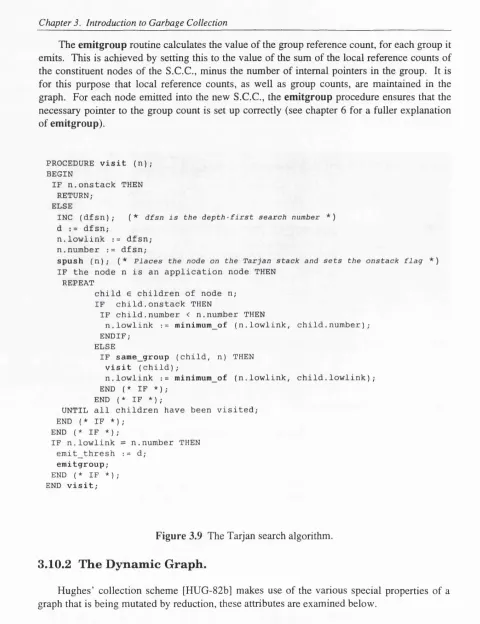
8.3.2 The visit Procedure. 148
8.3.3 The emitgroup Procedure. 150
8.3.4 The MA/V Procedure. 153
8.4 Conclusions. 156
Chapter 9. The Simulation. 157
9.1 Introduction to the Simulation. 157
9.2 Control of the Simulation. 158
9.2.1 Time-step Mode. 159
9.2.2 Event-driven Mode. 159
9.2.3 Control of the Collector's Cache. 160
9.2.4 Results Obtainable from the Simulator. 160
9.3 Results from the Simulator. 161
9.4 Comparison with Baker's Algorithm. 173
9.5 Conclusions. 176
Chapter 10. Conclusions. 177
10.1 Summary of the Thesis. 177
10.2 Appraisal of the Research. 178
10.3 Future Work. 179
Appendix A. Some Functional Programs. 182
Appendix B. The MALPAS Model of the Collector. 187
B .l IL Source. 187
B.2 The MALPAS Log File. 207
B.3 Output of the Compliance Analyser. 220
References. 242
Index. 254
-11-Figure 2.1 An example functional program 20 Figure 2.2 Simplified representation of the graph reduction process 23
Figure 3.1 Abstract syntax tree 26
Figure 3.2 General representation of a node in the reduction graph 27 Figure 3.3 Possible concrete representation of a reduction graph 27 Figure 3.4 Part of the reduction graph, showing reference counts 30
Figure 3.5 Weighted reference counting collection 35
Figure 3.6 A cycle within the reduction graph 36
Figure 3.7 Formation of the derived graph 38
Figure 3.8 An S.C.C. with group reference count 39
Figure 3.9 The Taijan search algorithm 40
Figure 3.10 Splitting of a cyclic structure 45
Figure 4.1 Schematic representation of the collector memory structure 48
Figure 4.2 Detail of local count overflow into the main heap 49
Figure 4.3 Detail of group data internal to the collector 51
Figure 4.4 Detail of accommodating group overflow data in the main heap 53
Figure 4.5 Overall reference count overhead versus heap size 55
Figure 4.6 A standard node 55
Figure 4.7 Overhead ratio, versus 5, for a variety of c 56
Figure 4.8 Overhead ratio for fixed collector memory versus Ô 59
Figure 4.9 Overhead ratio versus S.C.C. size 61
Figure 4.10 Comparison of the standard and limited-width techniques of
reference counting 62
Figure 4.11 Comparison of worst case memory overhead between
limited width technique and standard technique for a variety of c 63
Figure 5.1 A deadline 66
Figure 5.2 A hard deadline in a safety critical system 67
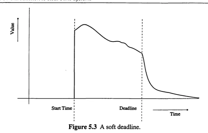
Figure 5.3 A soft deadline 68
Figure 5.4 A hybrid real time system 68
Figure 5.5 A taxonomy of real time systems 69
Figure 5.6 Relocating a cell in the standard copying collector 73
Figure 5.7a Relocating a cell in Baker's copying collector 75
Figure 5.7b Relocating a cell in Baker's copying collector (after copy) 75 Figure 5.8 The deletion of an arbitrarily large acyclic data structure 78
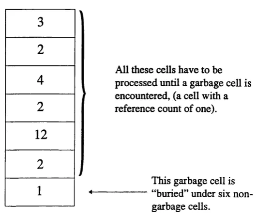
Figure 5.9 A T.B.D. stack with buried garbage 79
Figure 5.10 A Slip structure 80
Figure 6.1 Abstract high level view of the reduction architecture 84
Figure 6.2 An example of an acyclic data structure 85
Figure 6.3 Deletion of an acyclic structure 87
Figure 6.4 Incremental traversal of an acyclic structure 87
Figure 6.5 A large cyclic structure splitting into smaller S.C.C.s 88
Figure 6.6 Taijan's original algorithm 89
Figure 6.7 The original em itgroup procedure 90
Figure 6.8 Modified real time Tarjan algorithm 91
Figure 6.9 The real time em itgroup procedure 93
Figure 6.10 Deletion of a pointer using deleteref 94
Figure 6.11 Deletion of a pointer in a cycle waiting to be split 95 Figure 6.12 Deletion of a pointer from a partly scanned cycle 97
Figure 6.13 Deletion of a pointer from a fully scanned cycle 97
Figure 6.14 The real time deleteref procedure 101
-12-_________________ -12-_________________-12-_______________________________ List of Figures
Figure 6.15 Addition of a new application node 102
Figure 6.16 Sieve of Eratosthenes EASE program 103
Figure 6.17 Part of the directed graph produced by the Sieve of Eratosthenes 103
Figure 6.18 Order of visitation of nodes 104
Figure 6.19 Progress of a Tarjan search on a single S.C.C 104
Figure 6.20 An example EASE program 104
Figure 6.21 The addition of a new application node 109
Figure 6.22 The addition of a new application node during group emission 110
Figure 6.23 The newapp real time procedure 114
Figure 6.24 Addition of a pointer 114
Figure 6.25 The ad d ref real time procedure 115
Figure 6.26 The addref_ext real time procedure 116
Figure 6.27 The addition of a pointer in the addref_ext procedure 117 Figure 6.28 A simplified view of the collector's MAIN routine 118 Figure 6.29 A high level view of the collector's architecture 120
Figure 6.30 Collector and mutator operating in parallel 122
Figure 6.31 Pointer deletion stack element 124
Figure 6.32 A cyclic structure, with intra- and inter-cyclic pointer deletions 125
Figure 7.1 The integrated collector architecture 134
Figure 8.1 Example of (MALPAS) graph reduction 138
Figure 8.2 Compliance analysis 139
Figure 8.3 The formal model of a procedure using MALPAS IL 141 Figure 8.4 Output of the MALPAS reader for compliance analysis 143
Figure 8.5 The newapp procedure specification 148
Figure 8.6 Output of the MALPAS compliance analysis 150
Figure 8.7 The em itgroup procedure specification 152
Figure 8.8 The MA/A^ procedure of the MALPAS collector model 154 Figure 8.9 Output of the MALPAS compliance analysis for the MAIN procedure 155 Figure 9.1 Comparison of empirical and theoretical memory overhead values 161 Figure 9.2 No of searches in the main heap against max. numerical-width
of group descriptor number, for Sieve of Eratosthenes 162 Figure 9.3 Effect of cache on the number of heap searches, for Sieve of Eratosthenes 163 Figure 9.4 Number of collector heap read/writes versus cumulative total, (a = P = 2) 164 Figure 9.5 Number of collector heap read/writes versus cumulative total, (a = P = 3) 164 Figure 9.6 Number of collector local read/writes versus cumulative total, (a = P = 2) 166 Figure 9.7 Number of collector local read/writes versus cumulative total, (a = P = 3) 166 Figure 9.8 Number of collector operations versus cumulative total, (a = P = 2) 167 Figure 9.9 Number of collector operations versus cumulative total, (a = P = 3) 167 Figure 9.10 Number of mutator operations versus cumulative total 168 Figure 9.11 Number of mutator read/writes versus cumulative total 169 Figure 9.12 Number of uncollected cells versus collector time allocation 170 Figure 9.13 Number of collector local operations versus cumulative total 171 Figure 9.14 Number of collector local read/writes versus cumulative total 171 Figure 9.15 Number of collector heap read/writes versus cumulative total 172 Figure 9.16 Effect of changing T on the memory overhead ratio 173 Figure 9.17 Number of collector operations for Baker's algorithm (for newapp) 174 Figure 9.18 Number of collector operations for the reference counting garbage collector 174 Figure 9.19 Number of collector operations for Baker's algorithm (for deleteref) 175
-13-Figure A .l Factorial (8) 182
Figure A.2 Fibonacci series (8) 182
Figure A. 3 Sieve of Eratosthenes (to 31) 182
Figure A.4 Ackermann function (3,2) 183
Figure A. 5 Sort 183
Figure A.6 Cycle2 183
Figure A.7 Eight queens 184
Figure A. 8 Dynamic cycles 186
L ist o f T a b les.
Table 6.1 The scan condition of a node 108
Table 6.2 Compensation of emitgroup count totals for newapp 112
Table 6.3 Compensation of emitgroup count totals for addref_ext 117
Table 6.4 The main data structures of the collector 124
Table 7.1 Summary of the worst case temporal behaviour of the major
classes of collector routines 129
Table 7.2 Table of the worst case temporal behaviour of the major
classes of collector routines, in the integrated system 133
Table 8.1 Types of node 138
-14-C h a p ter 1. In tr o d u c tio n to P a r a lle l P r o c e ss in g .
1.1 B a c k g r o u n d .
In the early days of computer design there was a need to minimise the quantity of hardware used in the construction of machines. This was primarily due to purely pragmatic reasons stemming from the high cost and low reliability of hardware components then available. The von Neumann architecture [NEU-45] is ideally suited to these requirements and forms the familiar basis for the majority of general purpose digital computers in use today [TRE-82a].
With the advent of VLSI technology, vast improvements in machine performance have been realised, but it is now clear that diminishing returns are being made on further developments in component technology. This is largely due to, what has been dubbed by Backus [BAC-78], as the von Neumann bottleneck. This is the communications path that links the central processing unit (CPU) of a computer with its memory. The contents of the memory are modified a word at a time, over this communications link, until computation ceases. The bottleneck is both a physical barrier to speed, as well as an intellectual restraint, constraining the programmer to a word-at-a-time methodology of programming. This restraint is apparent in the form of conventional imperative languages, that are based upon the underlying von Neumann architecture.
Until recently much effort has gone into improving the speed of individual components, in order to enhance the overall machine performance. There have also been many architectures produced that are designed to increase the parallelism within the conventional von Neumann framework: vector pipelines, bit-slice, instruction-prefetch etc. [HES-87], have all been used. All these architectures are still based on the von Neumann model, i.e they are more or less enhanced SISD (Single Instruction Single Data stream) machines [HES-87].
1.2 P a r a lle l A r c h ite c tu r e s.
Alongside the largely commercial development of von Neumann enhancements, there has been a steady stream of academic projects, aimed at achieving a higher degree of parallelism using multiple processing elements. These projects have aU shared the common goal of increasing computational through-put by using several processing elements, each of which co operate on a single universal (programmed) problem.
The main thrust of parallel processing research started in the late fifties with a paper by Unger [UNG-58]. This described a machine with many processing elements, each stepping through the same sequence of instructions but handhng different data. This is a so called SIMD (Single Instruction Multiple Data stream) architecture. The idea was developed with the SOLOMON project [SLO-62] in the sixties and reached fruition with llliac IV [BOU-72]. The llliac IV project was a failure with a view to building a general purpose parallel super computer. This was because real applications could only exploit the processor array for a small percentage of the time it took to run them, the remaining code had to be executed on a relatively slow Burroughs scalar processor. Later projects, targeted at specific tasks, such as the ICL DAP [HOC-88] aimed at numerical processing, were much more successful. This machine was the first SIMD architecture to support active memory, both at system and software levels. Active memory uses the concept of distributing processing power into the memory of the machine. Another notable project was the Massively Parallel Processor (MPP), that contained 16,384 processors. It was designed for image processing and also met with a greater degree of success then the llliac IV [DUF-78, BAT-80].
-15-A development of the SIMD architecture is the systolic array [KUN-82]. This contains processing elements that are more specialised in their application. It displays interconnectivity which is more limited between individual processing elements. These machines are best suited to highly specialised mathematically intensive rôles, such as matrix multiplication, solution of linear systems and discrete Fourier transforms.
Another development of the SIMD concept is that of the Connection Machine [HIL-85]. This machine is designed to mimic directly the operation of the human brain. Each machine can have up to 64K processors. Such machines have achieved peak performance rates of 1,000 million instructions per second.
A milestone in the history of parallel processing was reached with the C.mmp project at Carnegie Mellon University [WUL-72]. A totally different approach to parallel processing was undertaken, each separate processing element executed a different set of instructions and communicated with each other over a bus network, based on a cross bar switch topology. This is a MIMD (Multiple Instruction Multiple Data steam) architecture. Several applications were developed to run on this machine, these varied in their success, depending on how effectively the apphcations could be partitioned onto the processing elements. The partitioning task was left to the responsibility of the programmer. Carnegie Mellon went on to develop a more versatile multiprocessor (Cm*) based on a system of clustered LSI 11 microcomputers [SWA-77]. The system was run under an operating system that organised the processing across the bus connected clusters. Provided that the applications required few remote references, good performance figures were obtained.
MIMD machines are in principle much more flexible than SIMD machines. This has lead to many projects based on this methodology of computer organisation. A notable class of such machines are those based on the hypercube interconnexion topology, conceived at the California Institute of Technology [SEI-85].
The data flow model of computation was developed as a means of controlling massively parallel hardware and efficiently developing naturally parallel code [DEN-80]. The principles of data flow were developed in the 1960’s by compiler writers, who used data flow graphs to do performance optimisations on standard serial computers. A data flow graph is a directed graph in which the nodes represent primitive functions. It was realised in the 1970’s that if data flow graphs were executed directly, then the architectures that execute them would be massively parallel. These ideas have lead to the development of data flow machines, such as Manchester University’s prototype data flow machine [WAT-79], as well as reduction based functional machines such as ALICE [DAR-81], GRIP [PEY-88] and many others [TRE-82b, VEG-84].
There are many surveys on the topic of parallel processing, and supercomputers, these include [BAE-73, KUC-77, FUL-77, DON-86, PAR-87, STA-87, BEL-89].
1.3 T h e S o ftw a r e P ro b le m .
A major problem with multiprocessor MIMD machines, arose through the method of programming. The task of dividing the program down into parallel streams was left to the programmer. If this division was not correctly performed, or if the algorithm was not amenable to such partitioning, then the time taken to synchronise processing between each processing element was found to be excessive. The problem was further compounded by the fact that the algorithms were first manipulated in a sequential regime, before being processed to expose parallel control paths. Often standard sequential imperative languages, with special
-16-Section 1.3 The Software Problem
constructs, were used to program these machines (e.g. parallel FORTRAN and later parallel C were used [KOV-83]). In complex applications the task of coordinating parallel streams of computation, with primitive programming constructs, such as FORK and JOIN, becomes untenably difficult. Recently concurrent languages have been developed, such as Modula-2 [WIR-83] and Ada* [BRAa-80]. These have better constructs that let the programmer initiate and coordinate multiple concurrent tasks. However, despite the apparent improvements made due to stronger programming constructs, these languages still depend upon the programmer uncovering parallelism within the algorithm that is under consideration.
Even advanced languages such as OCCAM [ELI-87], developed for use with the INMOS transputer [MAY-87, HOM-88], involve the programmer with the explicit use of such constructs as PAR and SEQ, controlling PARallel and SEQuential tasks. The language has the advantage that it is specifically targeted to the transputer. This is a development of the von Neumann architecture, that is designed to be run with multiple processing elements. However, OCCAM still suffers from many programming difficulties associated with extended procedural languages within a parallel domain.
It is desirable therefore, that any language that is used to program a parallel machine uncovers any latent parallelism in the algorithm being used, without the programmer having explicitly to specify parallel program control.
Another issue to be considered, in the context of programming in a parallel environment, is programming productivity. It has been found that the productivity of a particular programmer is largely independent of the language in which he is working [EIS-85]. In large applications, comprising 200,000 or more instructions, productivity can be as low as three correct instructions per day [JON-78]. It is therefore desirable to make the language as powerful as possible, that is, to encompass more computing in each construct, rather than just providing more constructs to the programmer. It has been observed that modified imperative languages, with their additional constructs to handle concurrency, lower programming efficiency still further [KOV-83],
Up to 50% of the time spent by a programming team may be used in “program maintenance”. This comprises time spent sorting out unforeseen “bugs”, that are places where the program diverges from its required specifications. Without a formal form of program proof it is very difficult to produce bug free software. As a result of this, maintenance costs are extremely high in the case of large complex pieces of software. The difficulty of writing error free software for parallel architectures is compounded when modified conventional languages are used.
In order to examine some alternatives to standard imperative languages, it is necessary to clarify what is meant by an imperative language.
1.3.1 Im p e r a tiv e L a n g u a g es.
These are the familiar “traditional” languages, such as C [KER-88] and Algol [MCG-78] etc. They were a pragmatic development from the underlying von Neumann machine architecture and can be considered as a high-level abstracted model of this machine concept. These languages can be characterised by a number of attributes [VEG-84]:
Ada is a registered trademark of the U.S. Department of Defence.
-17-(a) Program variables imitate words in the machine. They are considered as locations where values can be saved. This is at the root of the intellectual bottleneck of word-at-a-time thinking.
(b) Control statements imitate jumps, for example the if-then-else construction, common in imperative languages.
(c) The assignment statement imitates the fetch and store instructions present in the underlying von Neumann architecture. This is analogous to the von Neumann bottleneck in an imperative language.
(d) Two, or more, algorithmically separated pieces of code may modify the same “global” variable. This interaction between two pieces of code can be undesirable, leading to unforeseen side-effects. Assignment statements thus interact via a global machine state.
(e) Much of the programming task is concerned with data manipulation, rather than basic algorithmic issues.
(f) It is difficult to achieve efficient parallel execution of programs, when several different asynchronous processes can have side-effects on each other, (i.e. they may affect one another in a way that was not specified when the system was originally designed).
(g) The imperative model is not founded on a sound mathematical base. This means that program proofs are difficult.
(h) Imperative languages are inherently sequential in nature.
1.3.2 A lte r n a tiv e s to Im p e r a tiv e L a n g u a g e s.
The difficulty of programming parallel machines with imperative languages, and their lack of useful mathematical properties that could be used in formal program proofs, has lead to research taking place to look at different approaches to programming. Some of the options are discussed briefly below.
1.3.3 L o g ic L a n g u a g e s.
These languages stem from work carried out in automated theorem proving. The basis for the languages is predicate logic [KOW-83, KOW-85]. Predicate logic allows relationships between objects to be stated and stored in a data base. The user can then ask questions about the objects and the logic language interpreter provides the necessary search algorithms to establish the truth of the proposition. Practical logic based languages, such as Prolog [CLO- 81], depend upon features that are not strictly part of the logical framework. These are necessary to provide a reasonable programming environment.
These languages appear to be ideally suited to artificial intelligence applications. They are not efficient, however, in handling numerically intensive work necessary in such areas as mathematical modelling, pattern recognition, digital signal processing etc.
-18-Section 1.4 Conclusions
1.3.4 D a ta F lo w L a n g u a g e s.
In this model the program is represented as a directed graph. Each instruction is data driven, i.e. the instruction is carried out when its operand arrives. New languages have been developed to exploit this architecture, such as the University of California’s ID, M .l.T.’s VAL [HAY-82] and Manchester University’s SISAL [WAT-79].
Even with such software developments, the underlying architecture makes the manipulation of data structures relatively difficult. This is because separate words in memory cannot be updated independently. This results in a problem when a data structure is changed, even if it is only a minor modification, the whole structure has to be copied and rewritten back to memory. This appears to be a major flaw in data driven architectures that hinders their use in numerically intensive applications [GAJ-82]. However, some data flow languages can update structures without copying, by use of 1-structures.
1.3.5 F u n c tio n a l L a n g u a g e s.
In the 1930‘s Alonso Church proposed the Lambda calculus as a means of formally reasoning about equations [CHU-36]. This lead to the possibility of mechanically evaluating expressions. Rosser developed this work [ROS-82], but little was achieved practically until the 1960’s when McCarthy described the first programming language, LISP [MCA-60, WIN- 81], that was loosely based on this mathematical framework.
Since then, other languages have emerged that are based on the Lambda calculus, or a similar algebra of programs. Such languages are know as functional languages (which are a subset of declarative languages). There are a number of properties (discussed in chapter 2) that make functional languages appear well suited to solve many of the problems raised by parallel processing projects. Functional languages form the basis for the discussion in chapter 2.
1.4 C o n clu sio n s.
In order to increase computational power of computers, much effort has been expended on the research and development of parallel machine architectures. In this chapter a very brief outline of some of the major classes of such machines has been presented.
The problems of programming parallel computers, in a conventional procedural language, were highlighted. Some alternative language types were mentioned and functional languages were introduced as a well suited candidate to solve some of the programming problems of a parallel machine regime.
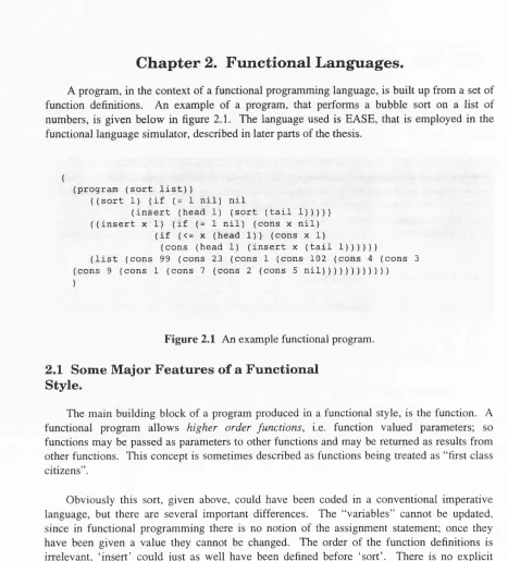
-19-A program, in the context of a functional programming language, is built up from a set of function definitions. An example of a program, that performs a bubble sort on a list of numbers, is given below in figure 2.1. The language used is EASE, that is employed in the functional language simulator, described in later parts of the thesis.
(program (sort list))
((sort 1) (if (= 1 nil) nil
(insert (head 1) (sort (tail 1))))) ((insert x 1) (if (= 1 nil) (cons x nil)
(if (<= X (head 1)) (cons x 1)
(cons (head 1) (insert x (tail 1))))))
(list (cons 99 (cons 23 (cons 1 (cons 102 (cons 4 (cons 3 (cons 9 (cons 1 (cons 7 (cons 2 (cons 5 nil))))))))))))
)
Figure 2.1 An example functional program.
2.1 Som e M ajor F e a tu r e s o f a F u n ctio n a l
S ty le.
The main building block of a program produced in a functional style, is the function. A functional program allows higher order functions, i.e. function valued parameters; so functions may be passed as parameters to other functions and may be returned as results from other functions. This concept is sometimes described as functions being treated as “first class citizens”.
Obviously this sort, given above, could have been coded in a conventional imperative language, but there are several important differences. The “variables” cannot be updated, since in functional programming there is no notion of the assignment statement; once they have been given a value they cannot be changed. The order of the function definitions is irrelevant, ‘insert’ could just as well have been defined before ‘sort’. There is no explicit order of execution implied in the program, unlike the situation found with imperative code, (though in functional languages data dependencies force execution order, and so there is a degree of implicit ordering).
2.1.1 R e fe r e n tia l T r a n sp a ren c y an d P a ra lle l
P r o c e s sin g .
The lack of the assignment statement and no explicit ordering of program execution, are the two important features of functional programming that lead to the notion of referential transparency [FlE-88]. This is the property that the value of an expression denotes a single value, not affected by its computational history. Evaluation of the expression may change its form, but not its value. This contrasts with imperative languages, which display referential opacity (i.e. the value of an expression may depend upon the history of the computation up to the point at which the expression is evaluated). Referential transparency serves to stabilise variables so that finite mathematical techniques can be employed to analyse code fragments, so facilitating the implementation of formal program proofs.
-20-Section 2.2 Architectures for Supporting Functional Languages
A most important feature of referential transparency is, perhaps, the removal of all side- effects. This makes programs less likely to suffer from “bugs” since there is no mechanism in which algorithmically separated sections of code interact with each other, via a global machine state. This is commonly seen where bugs (places where the behaviour of the program departs from its specification) arise in imperative code due to the unforeseen interaction of two variables. These effects are limited by modular programming, but the root cause of the problem, namely the assignment statement, is not eliminated by these techniques. Functional languages offer such a complete solution to this problem.
The ramifications of referential transparency go further than facilitating the formal verification of code; it enables a programmer to be freed from having to control program flow explicitly, along many different paths in a parallel machine. This is because any function can be evaluated at any time, or in any order. There is now an assurance that without side-effects, once the operands of a function become available, the function is guaranteed to evaluate to the same answer at any stage in the computational history. It is obvious that this feature, combined with the Church Rosser property [CHU-36] (that informally stated says that all reduction sequences, of the same code fragment, that terminate do so with the same result), facilitates parallel execution of programs. This is because separate processing elements can work on different parts of the algorithm without interfering with one another. Further more, since functional programs are amenable to formal mathematical manipulation and transformation, a program can be written in a clear and concise fashion and then manipulated, with confidence, to maximise execution efficiency.
Another interesting feature is lazy implementations [PEY-87a] of functional languages, that have the ability to handle some infinite, or non-terminating data structures. Lazy evaluation implies that arguments are only evaluated as they are required. An example, taken from [FIE-88], is given below of a function that returns its first argument if that is less than ten, otherwise it returns the second.
—f ( x , y) <= i f x < 10 t h e n x e l s e y; If we now evaluate the expression;
—f ( 4 , <n o n - t e r m i n a t i n g e x p r e s s i o n ) )
since only the first argument, 4, is required to produce the result, no attempt is made to evaluate the non-terminating expression, so the value 10 is returned as the correct result. In an
eager implementation an attempt would be made to evaluate the expression, resulting in a non-terminating result.
2.2 A r c h ite c tu r e s fo r S u p p o r tin g F u n c tio n a l
L a n g u a g e s.
The most common implementation technique, which is specifically designed to support functional languages, is graph reduction. This is briefly introduced below.
2.2.1 G rap h R e d u ctio n .
As has been seen, functional programs are built from a set of function definitions. The program is run by applying the topmost function to its arguments. In all but the most trivial of examples, this invocation causes other functions to be evaluated. In this way a graph is
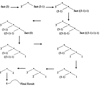
-21-spawned, with functions at the nodes and data paths at the edges. As an example, a recursive functional program to evaluate the factorial function is given below, along with a simplified representation of the graph that is created and evaluated throughout the computation of factorial (3). This graph is presented in figure 2.2.
{ ( f a c t n) ( i f (= n 0) 1 (* n ( f a c t ( - n 1 ) ) ) ) ) i n ( f a c t 3)
This program for factorial (3) is written in a general functional style. In pseudo-English we might describe the function thus:
defining the factorial o f n; if n is nought then return unity else multiply n by the factorial o f n minus one.
The graph can be seen to grow and then shrink to a final printable result as the reduction steps occur. The basis of graph reduction is that arguments of functions are shared whenever possible. There are a number of advantages in this:
(a) the argument may be massive, so copying would waste heap space;
(b) the argument may contain redexes (reducible expressions), and so copying could lead to wasted work since we would be duplicating the number of reductions performed, if both arguments were subsequently required.
Thus graph reduction proceeds with the substitution of pointers to function arguments and a graph is formed. The example given above, in figure 2.2, is simplified. For an in-depth discussion of reduction see [PEY-87a].
-Section 2.2 Architectures for Supporting Functional Languages
* *
fact (3) ► 3 fact (3-1)--- ^ 3 ^
(3-1) fact((3-l)-l)
* ---4--- *
^
3^
(3-1) (3-1)
((3-l)-l) fact(0) ((3-l)-l) fact (((3-1)-1)-1)
* ^ *
3 3 ' ^
(3-1) (3-1)
((3-D-l) 1 1 1
* 4--- * ^
^
3 ^ 1 ^ 2 3 3 ^
I
2 1 (3-1) 1Final Result
Figure 2.2 Simplified representation of the graph reduction process.
A common implementation technique uses combinators [TUR-79]. These are employed in the functional language implementation, described in chapter 9. As an alternative to combinators, a more sophisticated technique, supercombinators, may be used [HUG-82a].
2.2.2 A lte r n a tiv e A p p r o a ch e s to th e
Im p le m e n ta tio n o f F u n c tio n a l L a n g u a g e s.
There are a number of different approaches that have been explored for the implementation of functional languages. One is the so called S.E.C.D. machine, that employs an environment-based computational model, based around four stacks, eponymously, S, E, C and D. This environment provides direct access to the free variables in any lambda abstraction, solving the free variable problem [FIE-88]. This machine was built to run McCarthy’s LISP language [MCA-60] and was designed to run LISP on a serial von Neumann machine with the addition of the S.E.C.D. environment stack to facilitate compilation of lambda expressions containing free variables [LAN-82, HEN-80].
Data flow is a method in which the model of computation is to view the data as an active entity, that flows through a collection of static transformers or functions [FIE-88]. The most common implementation of data flow is the model in which the operators wait until the required data flows are passed and then operate on that data, this is termed data-driven data flow.
-23-An alternative to graph reduction is string reduction. Graph reduction relies on sharing arguments, the alternative of copying arguments leads to a tree structure, and is known as tree (or more commonly string) reduction. The overheads of string reduction are normally considered prohibitively expensive, though Mago’s machine [MAG-80] implements string reduction and relies on massive paralleUsm to overcome the inherent inefficiency of this type of implementation.
2.3 A p p lic a tio n s fo r F u n c tio n a l L a n g u a g e s.
Functional languages offer possible solutions to many problems that have afflicted proceduraUy programmed systems. They offer an alternative that may prove viable as a general purpose programming methodology. There are, however, a number of applications areas to which functional languages seem particularly suited.
An obvious application for functionally programmed systems are for safety critical situations, such as “fly-by-wire” aeroplane control [MEL-82], or safety equipment in the oil industry. The ability rigorously to prove programs are correct is extremely important in such applications.
As has been mentioned, the property of functional languages possessing referential transparency offers the possibility of parallel architectures that are both more easily programmed and more efficient than their proceduraUy programmed counterparts. This is one of the reasons why there is a growing effort to develop these languages for fifth generation (paraUel) computers [SAR-88].
Functional programmed systems are also of interest in both real time and artificial intelligence environments. This is particularly true for those that are supported by a parallel architecture, where a uni-processor approach would not provide sufficient computational power to meet the needs of the application. Despite the difficulties associated with garbage coUection (see chapter 3) functional languages have been used for inteUigent robotics programs (a real time appUcation) and algebraic manipulation systems (an interactive application) as early as the mid 1970’s [STE-75, WAD-76].
Functional languages are also used in other applications with real time constraints. An interesting recently developed functional language, is a one named Fugue [DAN-91]. This has been developed for sound synthesis purposes. It uses the properties of functional languages to manage complex musical structures, and employs a temporal notation to handle sound duration specifications. Nilsen also suggests that applications such as computerised medical instrumentation, robotics and voice recognition, that are currently programmed principally in lower-level languages, such as C and assembler, would be enhanced by the use of higher-level functional languages, if these languages could meet the real time responses necessary.
Digital signal processing is an area where very high processing rates are demanded. It has been pointed out by Burnett [BUR-87] that, though signal processing covers a wide range of problems, there are a number of common algorithms that dictate the principal requirements of a signal processor. These are namely: the discrete Fourier transform, convolution and recursive filtering. Burnett beheves, along with others, that reduction architectures are
"'almost ideal in principle" for digital signal processing apphcations, if the inefficiencies traditionally associated with functional language implementations (specifically, the garbage collection problem) can be eliminated.
-24-Section 2.4 Conclusions
Sanders [SAN-89] has made an interesting study of comparing the use of three functional languages (Hope, Miranda and ML) for the implementation of a real problem in an industrial environment. The solutions obtained in each case are compared to ones obtained for systems written in Ada and C. The results showed that compared to Miranda, the development time (for 1503 lines of Ada) was about 5 times greater for the Ada system. The code for Miranda was at least three times as compact, in terms of number of lines, compared to Ada. This demonstrates the greater expressive power of a functional, as compared to procedural language. Execution speed for Hope and ML were comparable to the times for C (but Miranda was much slower). He concludes that functional languages offer many advantages for the commercial environment, provided that the systems are developed further. Other studies between declarative languages are made in [HAI-89, FLE-90].
2.4 C o n c lu sio n s.
This chapter introduced the major facets of the functional style of programming. The features highlighted were shown to facilitate programming machines based upon parallel architectures.
Some of the major machine architectures, that are designed to support functional languages, were introduced. The most common architecture, graph reduction, was briefly outlined.
The chapter concluded with a summary of some of the important application areas for functional programming.
-The example of the reduction of a factorial function, given in chapter 2, figure 2.2, shows a typical way in which a graph changes during reduction. The building of new parts of the graph demands that new cells are allocated from memory. Cells are obtained from a memory that is organised as a heap. The term heap impUes that from a graph reduction point of view, in this type of storage, actual absolute cell addresses are unimportant. The sahent feature of this memory organisation is the pointer structure in the reduction graph.
During the reduction process pointers to cells will be discarded. When a cell no longer has any pointers referencing it then it is said to be garbage, i.e., it plays no further rôle in the graph reduction process. When new cells are allocated to the graph, these can be sourced either from the pool of unused cells in the heap, or taken from a hst of reclaimed garbage cells, that is termed the free list. If no reclamation of garbage cells occurred then, with large apphcations, the heap would be eventually exhausted and computation prematurely cease.
Garbage cell identification and recovery is comphcated by the fact that there may be many pointers to a particular cell and pointers may form circular structures. It is the job of the garbage collector to perform the task of identification and recovery of all redundant cells.
Before exploring the different options available for garbage collection, the next short section will give a simple example of how the graph may actually be represented within the machine.
3.1 C o n cr ete R e p r e s e n ta tio n o f th e G raph.
As an example, consider the simple expression (+ 4 2). This is simply the apphcation of the function *+’ to the two arguments ‘4 ’ and ‘2 ’. This expression can be represented as an abstract syntax tree, as shown in figure 3.1.
y
+
Figure 3.1 Abstract syntax tree.
The symbol is used to denote that this is an application node. This is an example instance of the tag of a node.
There are a number of different ways in which abstract syntax trees can be represented within the machine, in essence they are similar to the scheme given below.
Each node in the tree is represented by a small contiguous area of store, called a cell. The cell comprises a tag that identifies its particular type, (e.g., apphcation, number, built-in operator, CONS cell etc.), and zero or more fields. The most common implementations have
Section 3.2 The Significance o f Garbage Collection
fixed-size cells with two fields, but variable-sized cells with an arbitrary number of fields are possible.
For a cell containing two fields, a cell may be represented thus: Tag I Fieldl I Field!
Figure 3.2 General representation of a node in the reduction graph.
The fields may contain either the address of another cell, in which case it is a pointer, or alternatively it contains an atomic (non-pointer) data value. A possible concrete representation of the expression (+ 2 4) is given below (this is a boxed representation, see section 3.5 and [PEY-87a]).
@ /
@ /
p +
N 2
N 4
Figure 3.3 Possible concrete representation of a reduction graph.
The N tag signifies a number and P a built-in function. There are a number of variations based upon this theme [CLA-80, RIC-85], but essentially the architecture is that of the fixed length cell with tag nodes.
The functional language interpreter used in the simulator, described later in the thesis, uses fixed length cells.
3.2 T h e S ig n ific a n c e o f G arb age C o llectio n .
It is becoming increasingly clear that garbage collection is one of the most important efficiency issues that must be addressed in any functional language implementation. Studies with large implementations in LISP have shown that 10 to 40 per cent of processor time is actually spent in garbage collection [STE-75, WAD-76]. Unless the question of garbage collection is resolved, then functional language implementations will always be prohibitively inefficient, as compared to traditional imperative languages.
Morris [MOR-83] has stated, after much practical experience with functionally programmed systems, that the cost of garbage collection is the most important problem, particularly for systems with real time constraints. More modem techniques in garbage collection have ameliorated this problem to some extent, nevertheless it remains a major obstacle to the efficient implementation of functional languages, particularly in real time systems.
-3.3 M a rk -S ca n G a rb a g e C o lle c tio n .
This is the commonest form of garbage collection. A mark-scan algorithm operates in two phases. The first phase is that of marking all cells in the entire accessible structure of the heap. A mark bit is set on each cell that is reachable, i.e., is not garbage. This can be achieved by tree-traversal algorithms [KNU-68], The standard methods use a stack, that can grow to considerable size, during the marking phase, though the stack depth can be limited using a fixed length stack, at the cost of increased processing [KNU-68]. A development of the marking algorithm is due to both Deutsch and the pair Schorr and Waite (independently of each other) [SCH-67]. This uses a link-reversal technique to eliminate the memory overhead of the stack with only the inclusion of a single mark bit for each cell.
In the standard tree-traversal method each cell is visited twice during the marking phase, with the Deutsch-Schorr-Waite method, this is increased to thrice. This obviously leads to increased processor overhead. Schorr and Waite proposed a hybrid scheme that uses a fixed depth stack wherever possible, but employs the link-reversal technique when this overflows [KNU-68].
The next phase of the garbage collection is the reclamation of garbage cells, or scan
phase. The simplest method for achieving this is to sweep linearly the entire heap. Any cells that have not been marked as accessible during the mark phase are reclaimed and appended to the free list, administered by some form of storage allocator.
Compaction of the memory can be achieved at this stage, rather than simply appending the newly reclaimed cells to a free list. This is done by scanning the memory twice. In the first scan two pointers are used, one starting at the bottom of the heap and the other at the top. The bottom marker is incremented until it points to an unmarked cell; the top pointer is then decremented until it points to a marked cell. The contents of the marked cell are then swapped with the unmarked one, a pointer to the new cell is placed in the old and the mark bits are turned off. When the two pointers finally meet, all the cells have been compacted in the lower section of the heap. The second sweep occurs in the compacted area to readjust pointers to cells that have been moved.
It should be noted that with this method of compaction, cells that point to one another will not necessarily occupy contiguous positions in the heap after compaction, i.e., the compaction is arbitrary in nature. Other, more sophisticated (and much more processor intensive) algorithms can be employed to place nodes which reference one another in contiguous positions. This achieves linearising compaction.
3.4 C o p y in g G a rb a g e C o lle c tio n .
Copying collection was first described by Minsky [MIN-63], according to Baker [BAK-78]. This method of collection works by copying the entire accessible structure in the heap from one portion of the heap (from-space) into another area of memory {to-space). In principle, as the entire accessible graph structure in the from-space is traversed, each referenced cell is moved to the to-space. The original reference to the cell is adjusted so that it points to the moved cell, in to-space. In addition, the new address of the cell, that has been moved, is then left behind in the from-space, this is termed a forwarding address or an
invisible pointer. This address is used to update cells that hold pointers to this moved cell, that may be encountered later in the collection process. At the end of the collection cycle, the cells remaining in the from-space must be garbage and so can be discarded.
-28-Section 3.5 Reference Counting Garbage Collection
As the copying occurs, the cells being moved to the to-space are placed adjacent to one another. As a result, once copying is complete, there is a contiguous area of new cells that can be allocated as reduction proceeds. There is therefore no need to maintain a free list of cells. When the to-space is filled up, the two spaces are then flipped, (to-space becomes from-space and vice versa). The process is then repeated.
A refinement of this scheme is due to Lieberman and Hewitt [LIE-83]. The scheme involves splitting the heap into n regions, n-\ of which are active. Each region is then collected by swapping it into the one, spare inactive region. Each region is also given a
generation number, that indicates when the space came into use. Lieberman and Hewitt made and used the observation that, the newer the region the more likely it is to contain garbage.
This is utilised so that newer regions are collected more often than older ones. Another empirical observation is made in this technique, that is most references across region boundaries tend to be to older regions. This is made use of by keeping an entry table of pointers to a particular section from older regions. When the region is garbage collected, only younger regions have to be searched, for pointers into this region.
Baker [BAK-78] has developed a real time version of the standard two space copying collector. This is described in greater depth in chapter 5
Morris [MOR-78], describes a collector that does not require a spare region, into which cells are swapped. The algorithm he has developed also ensures that cells remain in the same order as in the ffee-space. Unfortunately, the technique is not suitable for real time collection, because the mutator cannot claim new cells until the whole collection process has ceased.
3.5 R e fe r e n c e C o u n tin g G arb age C o llectio n .
This method relies on an extra field associated with every cell in the heap. This is the
reference count field. This field is maintained with the number of references to that particular cell, i.e., the number of pointers to the cell. Whenever a pointer is added to the graph, which points to the cell in question, then the reference count field is incremented. When a pointer is discarded to the cell then the reference count is decremented. If the reference count falls to zero, then the cell must be garbage since there are no references to it [COL-60].
Figure 3.4 shows diagrammatically reference counts in a typical part of a graph, the last field in each cell holds the reference count. By way of contrast to section 3.1, an unboxed
representation of the graph is used here, where data objects are completely described by a single field. This is unlike the boxed representation of figure 3.3. In this representation each field carries an extra marker flag, that is the pointer-bit. This distinguishes the field as a pointer, or data object. This field is shown greyed in figure 3.4.
-29-The end fields are reference counts
@
This node is garbage, it has a zero reference count.
0
Figure 3.4 Part of the reduction graph, showing reference counts.
The garbage collector maintains the reference counts for each cell as pointers are added and deleted. Once the reference count of a cell has fallen to zero then the cell can be added to the free list and reused. The bottom-most cell shown is garbage, since its reference count is zero.
3.6 O th er M eth o d s o f D e a lin g w ith G arbage.
Burnett [BUR-87] uses a different form of garbage collection in his M kl architecture. This machine was developed for the graph reduction of the functional language FP [B AC-78]. He uses two spaces, termed scratch space and save space. At compile time, the compiler determines which results are to be saved or placed in scratch space. The user inserts a mark next to a function to indicate that the result should be saved. When so marked, the computed result is placed in save space at run time. If the result is only required as an intermediate result, then scratch space is used and the result is collected as garbage after use by the next function. The two logical areas, nominated as scratch space and save space, are swapped for nested calls to functions, so that intermediate results are saved correctly.
The method is very limited in its application, since it would be difficult to implement in languages other than FP [BUR-89]. It also suffers from the disadvantage that the programmer has explicitly to control garbage collection.
Wadler has suggested a method of avoiding garbage collection altogether, based on a language founded on linear types [WAD-90]. The technique effectively performs memory allocation in advance. Such techniques are referred to as compile time garbage collection.
More recently a paper by Wakeling and Runciman [WAK-91] gives some very disappointing results for compile time garbage collection, based on Wadler's methods. They point out some inherent failings in the method, due to lost optimisation at compile-time and extra data structures that have to be created at run-time.
-30-Section 3.7 An Appraisal of the Various Garbage Collection Strategies
3.7 A n A p p r a isa l o f th e V a r io u s G arb age
C o lle c tio n S tr a te g ie s.
Peyton Jones [PEY-87a] lists the most important criteria when assessing a particular garbage collection technique. These are summarised below:
(a) What are the space and time overheads?
(b) Is compaction supported? An issue that is important in variable-length cell systems.
(c) Is the method efficient in sparsely used heap and virtual memory? (d) Can it operate in parallel with graph reduction? (This is sometimes
termed noisy heap operation).
(e) Can it respond within bounded time? This is vital for real time systems. (f) What is the effect of heap occupancy?
(g) Can it recover garbage cyclic structures?
(h) How does it perform in a multiple processor element environment?
The next three sections compare the principal types of garbage collector, against the criteria set out above.
3.7.1 M ark -S can C o llec tio n .
The space overheads are a mark bit in each cell and a stack, used to guide the recursive tree-walk in the mark phase. This stack is bounded in size only by the number of cells in the heap, but, as has been explained, this can be limited in size or eliminated altogether by using the Deutsch-Schorr-Waite pointer-reversal algorithm (at the expense of a further mark bit per cell).
The CPU overheads are relatively light, although they increase with pointer-reversal techniques.
Compaction can be achieved in the scan phase, but again there is a processing overhead to pay.
This technique gives very poor performance in situations where the heap is sparsely used, or virtual memory is employed. This is because all accessible cells are visited, not just those in immediate use. Without compaction, in a sparsely used environment, poor paging behaviour becomes a severe problem. The arbitrary compaction, that is usually supported in mark-scan systems, does httle to alleviate this problem.
Algorithms have been presented that allow collection to occur at the same time as the useful job of graph reduction. With the standard technique garbage collection is carried out when the heap is almost full, then there is an “embarrassing” pause whilst the collection occurs. On large systems this can take minutes and obviously is both inconvenient for the
-31-user, and rules out any form of real time operation. It has also proved very difficult to forecast when collection will occur. The parallel algorithms, [STE-75, KNU-68, DIJ-78], are considerably more complicated than the standard mark-scan techniques and none have been shown to be guaranteed to respond in bound time. They obviously demand much higher processor overheads (due to processor-collector synchronisation etc) than their “stop-the- world” counterparts. These are discussed in greater depth in chapter 5.
As the heap fills up, the performance of mark-scan techniques degrades sharply. This is because all accessible cells have to be visited in order to recover garbage cells, even though this may yield only a few cells.
Cychc structures offer no special problems to mark-scan techniques.
Mark-scan collection within a parallel processing environment is difficult to achieve, especially when noisy heap collection is called for. This is because the action of the collector is essentially global, and so a large degree of “choreography” between processors (processor synchronisation) has to occur when collection takes place. This inevitably leads to some pause in the graph reduction, again making this technique unsuitable for real time applications. There have been algorithms developed that are designed to implement forms of mark-scan collection within distributed systems. These include ones by Hudak [HUD-83], Ali [ALI-84] and Hughes [HUG-85], among others.
3.7.2 C o p y in g C o lle c tio n .
In systems where virtual memory is not used then there is a 100 per cent space overhead, for simple two space collectors. This is greatly reduced in virtual memory systems, where parts of the heap space that are not being currently used are paged out. The processor overhead appears to be less than that of the mark-scan technique (when basic copying collectors are used).
Compaction is inherent in this method whilst the from-space to-space copying occurs. It can be easily arranged that cells that point to one another are placed in contiguous areas of the heap, so that linearising compaction occurs. Because of this, the performance in virtual memory systems is greatly improved, due to data structure locality facilitating paging operation.
The behaviour of this technique in sparsely used heaps is much better than mark-scan, since there is no sweep phase throughout the whole heap. However, in heavily used heaps the performance degrades, as with mark-scan, since all accessible cells have to be visited.
Copying, in its basic form, demands that the reduction process halts, causing the same problems as with mark-scan. However, noisy heap operation can occur with an incremental copying scheme [BAK-78]. This modified scheme greatly increases both CPU time and heap space overheads.
This method, like mark-scan, is also fundamentally global throughout the heap, this leads to the same objections for employing it in parallel architectures, namely a high degree of processor-processor interlock synchronisation is required as collection occurs.
Also, like mark-scan, cyclic structures present no special problems to a copying garbage collector.