R E S E A R C H
Open Access
Improving microservice-based
applications with runtime placement
adaptation
Adalberto R. Sampaio Jr.
1*, Julia Rubin
2, Ivan Beschastnikh
3and Nelson S. Rosa
1Abstract
Microservices are a popular method to design scalable cloud-based applications. Microservice-based applications
(μApps) rely on message passing for communication and to decouple each microservice, allowing the logic in each
service to scale independently.
ComplexμApps can contain hundreds of microservices, complicating the ability of DevOps engineers to reason
about and automatically optimize the deployment. In particular, the performance and resource utilization of aμApp
depends on the placement of the microservices that compose it. However, existing tools forμApps, like Kubernetes,
provide minimal ability to influence the placement and utilization of aμApp deployment.
In this paper, we first identify the runtime aspects of microservice execution that impact the placement of
microservices in aμApp. We then review the challenges of reconfiguring aμApp based on these aspects. Our main
contribution is an adaptation mechanism, named REMaP, to manage the placement of microservices in an
μApp automatically. To achieve this, REMaP uses microservice affinities and resource usage history. We evaluate our
REMaP prototype and demonstrate that our solution is autonomic, lowers resource utilization, and can substantially
improveμApp performance.
Keywords: Microservices, Runtime adaptation, Optimization
1 Introduction
As business logic moves into the cloud, developers need to orchestrate not just the deployment of code to cloud resources but also the distribution of this code on the cloud platform. Cloud providers offer pay-as-you-go resource elasticity, and virtually infinite resources, such as CPU, memory, disk, and network bandwidth. The man-agement of these cloud resources, however, is a major challenge, leading to new roles like DevOps engineers. In this context, microservices have become an essential mechanism to provide the necessary deployment flexi-bility and at the same time take advantage of abundant resources [1].
A microservice is a decoupled and autonomic soft-ware, having a specific functionality in a bounded con-text. The decoupling and well-defined interfaces provide
*Correspondence:[email protected] 1Center of Informatics, UFPE, Recife, Brazil
Full list of author information is available at the end of the article
the ability for microservice-based applications (μApps) to scale in/out seamlessly and for developers to perform upgrades by deploying new service versions, all without halting theμApp. The decoupling also allows microser-vices to be developed using different programming lan-guages.
Despite the many similarities between services and microservices [2], there are some fundamental differ-ences, mainly related to their execution. Languages like
WS-BPEL1 describe the workflow of service
composi-tions. By contrast, aμApp workflow is not formally
spec-ified. TheμApp communication must be monitored to
infer the underlying workflow.
A downside of using microservices is their management complexity. A microservice may have different behaviours while it executes, which is reflected in both the volatil-ity of resource usage and changes in its workflow. Hence, initial μApp deployment choices, like the placement of microservices, may be sub-par later.
The management ofμApps is performed by engineers aided by tools that provide timely data about applications (e.g., resources usage) and microservice lifecycle manage-ment (e.g., replicating microservices on demand). How-ever, these management tools are incapable of providing crucial runtime data like the amount of data exchanged between two microservices or the resource usage history of a given microservice. As a consequence, existing tools are unable to perform management operations, like the replacement of microservices, based on actual execution data.
At runtime, microservices that compose an application can interact and exchange a significant amount of data, creating communication affinities [3]. We define affin-ity as a relation between two microservices given by the number and size of messages exchanged over time. These inter-service affinities can have a substantial impact on the
performance of the μApp, depending on the placement
of the microservices, e.g., microservices with high affin-ity placed on different hosts will have worse performance due to higher communication latency. Making this more complex is the fact that affinities change at runtime.
In addition to affinity, developers must also account for microservice’s resource usage history to optimize μApp placement. For example, microservices with a history of high resource usage should not be co-located on the same host. Also, service upgrades and different workflows along
the μApp execution change the resource consumption
and affinities.
Existing management tools, like Kubernetes2 and
Docker Swarm3, allow DevOps engineers to control
μApps by setting resources thresholds on the microser-vices. The management tools use this information to decide when to scale in/out each microservice and where to place microservice replicas. At runtime, the man-agement tools continuously compare the instantaneous resource usage of the microservices with their resource threshold. When the resource usage reaches the limit, the management tool starts the scaling action. During scale out, existing management tools select the hosts where to place the microservices replicas based on the set thresholds instead of their history of resource usage. As our experiments will show, in most cases a resource threshold is unrealistic and leads theμApp to waste clus-ter resources or to lose performance due to resource contention.
Management tools should be aware of runtime and
historical data for μApps to avoid misplacement of
microservices. Although these tools can use instanta-neous data to perform scale up/down activities, this is not enough in cases where a re-arrangement of microser-vices is necessary. We therefore propose a new tool that uses history and runtime data to better manage microservices.
The focus of our work is on improving the
manage-ment ofμApps through the use of runtime data as the
basis for automatic management tasks, such as placement optimization.
Next, we overview three challenges to realizing adapta-tion ofμApps:
– Challenge 1: Unified monitoring ofμApps.
Existing management tools can collect and expose many resource metrics from executingμApps. However, eachμApp uses its own monitoring stack. The diversity of monitoring options creates a semantic challenge, requiring a single unified data model.
– Challenge 2: Finding a high-performing placement.Microservices are usually placed using static information like the available host resources. However, this strategy risks loweringμApp performance by putting high-affinity microservices on different hosts or by co-locating microservices with high resource usage. Hence, it is necessary to find the best performing configuration that maps microservices to servers. This need leads to two sub-problems: (1) a large space of configurations: withn servers and m microservices there aremn
possible configurations; and (2) the performance of a
μApp configuration changes dynamically. – Challenge 3: Migrating microservices.Existing
microservices management tools do not present alternatives to performing live migration of microservices between hosts. This migration is necessary to provide seamless runtime adaptation.
Our proposal is an adaptation mechanism, named
REMaP (RuntimE Microservices Placement), that
addresses the above three challenges and automatically changes the placement of microservices using their affinities and history of resource usage to optimize the μApp configuration. In our prior work [4], we considered
Challenge 1by defining a model to support the evolution ofμApps. In this work, we refine the ideas presented in [4] to addressChallenge 2andChallenge 3. The core of this work is about addressingChallenge 2. We present our view on runtime adaptation ofμApps and the challenges with optimally arranging microservices. Finally, in this work, we partially addressChallenge 3.
REMaP approach overview. Our solution uses a
MAPE-K based [5] adaptation manager to alter the
placement of μApps at runtime autonomously. REMaP
uses [email protected] concepts and abstracts the diver-sity of monitoring stacks and management tools. In this way, our solution provides a unified view of the
cluster and the μApps running under the adaptation
REMaP groups and places microservices with high affinity on the same physical server. This strategy is in contrast with the existing static approaches that rely on
information provided by engineers beforeμApp
deploy-ment. For instance, Kubernetes arranges microservices in a cluster based on the resources limits (max and min) and tags set by engineers. Kubernetes does not consider information about the relationship between microservices
to improve the deployment of theμApp by reducing the
hosts to be used and the communication latency between microservices. Hence, our adaptation manager can pro-vision resources based on actual microservice resource utilization, avoiding resource contention/waste during μApp execution. Moreover, the co-location of microser-vices decreases the impact of network latency on the μApp workflow, which improves overall application
per-formance. At the end of the adaptation, the μApp has
an optimized configuration that reduces the number of hosts needed to execute theμApp and improves its per-formance as compared to an unoptimized deployment.
Prior work focusing on adaptation ofμApps proposed
to change the μApp deployment at runtime to provide
runtime scaling [6] or to update a running deployment to a new version [7]. These approaches do not improve the placement of the constituent microservices nor consider the resource usage history when formulating an adapta-tion. These tools use instantaneous metrics gathered from theμApp, which do not reflect their real resources needs over a longer time period.
We evaluated REMaP in two scenarios, and we com-pared the results of an optimization algorithm based on SMT (Satisfiability Modulo Theory) [8] with a
sim-ple variation of a First-Fit algorithm [9]. We made
this comparison to evaluate the feasibility of finding an optimal placement instead of an approximation, given the complexity of the problem. In the first scenario, we used the proposed mechanism to compute the adaptation of synthetic application graphs, having a different number of microservices and affinities. In this scenario, we realized adaptations that saved approximately 80% of the hosts used initially by the μApp. This evaluation shows that our approach produces better results onμApp with dense topologies. Moreover, when using SMT, the adaptation
mechanism was unable to work onμApps larger than 20
microservices. Hence, although our heuristic cannot guar-antee an optimal result, it can compute placements for μApps of any size.
In the second scenario, we used REMaP to adapt a
ref-erence μApp4 running on Azure. In this scenario, we
achieved a performance improvement up to 62% and saved up to 40% of hosts used in the initial deployment. Moreover, we found that a poor placement that uses the same number of hosts can decrease the overall perfor-mance of theμApp by 150%, indicating that the placement
requires special care by engineers; care that our approach automates.
The rest of this paper is organized as follows. Section2
introduces the concepts necessary to understand the rest of the paper. Section3discusses the challenges of general-purpose runtime adaptation of microservices. In Section4
we discuss the specific challenges to adapt μApps by
re-configuring the microservices placement at runtime. Sections5and6present the design and implementation of our solution, respectively. Section7presents the evalu-ation of the proposed approach. We contrast with related work in Section8. Finally, Section9concludes and notes some avenues for future research.
2 Background
2.1 Microservices
The microservice pattern is an architectural style of
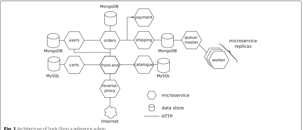
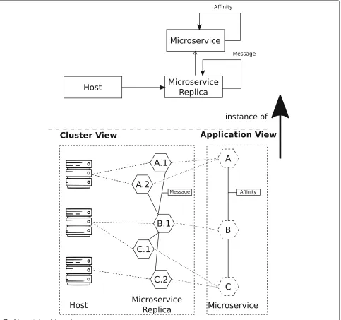
service-oriented computing whose cornerstone is a high degree of decoupling [10]. A microservice is an auto-nomic, and loosely-coupled software having a specific functionality in a bounded context. As shown in Fig.1, microservices (hexagons) belonging to a microservice-based application (μApp) communicate using lightweight communication protocols like HTTP. These microser-vices are usually deployed in containers, a lightweight alternative to traditional virtual machines [1]. The use of containers facilitates the elasticity of theμApp: only some parts, and not the entire application, need to expand and contract in response to changing workload. For instance, suppose that the microservices related to orders have a higher load than those associated with sign-ups during a Christmas sale. In this case, just the first set of ele-ments needs to scale up to avoid bottlenecks, while the others can contract and release resources for use by other components. This behaviour is not available in monolithic applications.
Figure1shows the design of Sock-shop, a microservice-based reference application [11]. Sock-shop adopts good practices inμApps, like data storage and communication middleware (e.g., RabbitMQ) wrapped by microservices, and containers, which provide flexibility to the μApp. Sock-shop is composed of a hub of six microservices (front-end, orders, users, carts, catalogue, and shipping), their respective data storage, and auxiliary microservices. The decoupling provided by microservices facilitates
the maintainability of μApps by reducing the
Fig. 1Architecture of Sock-Shop a referenceμApp
Despite the many similarities between services and microservices [2], there are some fundamental
differ-ences. Developers use languages like WS-BPEL [12] to
define the workflow of a service-based application and use an engine to execute the workflow. By contrast, the flow of messages exchanged by microservices that compose a μApp defines the workflow. Hence, it is necessary to change at least one microservice to modifyμApp’s work-flow, e.g., by replacing it. Consequently, more caution is needed to evolve aμApp.
μApp engineers use management tools, like
Kuber-netes, to control aμApp automatically. Unlike autonomic applications, whose management requires either mini-mal or no human intervention, microservice manage-ment tools need an engineer to guide the managemanage-ment tasks. These tools can automatically update and upgrade a μApp, e.g., scale in/out or roll out/back a microser-vice, by following the engineer’s instructions. In general, engineers set the maximum and the minimum number of replicas that aμApp should have, and a resource threshold that triggers the scaling process. Moreover, the manage-ment tool automatically deploys a microservice onto the cluster by considering attributes set by the engineers at deployment time. However, this placement is not opti-mal and can jeopardize the execution of aμApp in some circumstances.
2.2 Autonomic computing
Autonomic computing refers to self-managing computing systems [13]. Self-management means that the system can control itself, and human intervention is not necessary for activities such as optimization, healing, protection, and configuration.
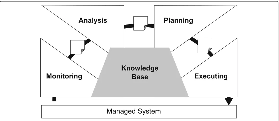
A self-managed system must monitor itself and the envi-ronment, analyze signals produced by the monitoring, and applies actions in response, perhaps by modifying itself. These steps repeat indefinitely as a control loop. IBM systematized this loop by proposing a reference
model for automatic control loops called MAPE-K [5]
(Fig.2).
In MAPE-K, the monitor collects data from the
managed system and dispatches them to the analyzer
that reasons over them or infers new information. Next, the analyzer forwards the result of the
anal-ysis to the planner that computes an adaptation or
management plan. The executor receives the plan and
applies it to the managed system. Lastly, components
of MAPE-K share aknowledge basethat maintain rules,
properties, models and other kinds of data used to steer how to provide autonomy to the underneath system.
Szvetits and Zdun [14] and Krupitzer et al. [15]
surveyed several strategies for adapting complex, het-erogeneous, and dynamic systems that do not apply the adaption plan directly to the managed system. In this case, the adaptation plans are applied to
models maintained at runtime ([email protected]) [16].
Fig. 2MAPE-K reference model
3 Challenges of runtime adaptation of microservices
Runtime adaptation is inherent to μApps, which can
evolve during execution. The decoupling promoted by the microservice architectural style allows updates and upgrades at runtime without pausing or terminating the application. Scale in/out operations usually update
μApps, while roll out/back operations upgrade the
microservice versions.
In our context, an adaptation consists of (1) replac-ing one microservice instance with another, usually on a different host, or (2) creating new microservice repli-cas. Management tools execute such adaptations. How-ever, engineers use these tools and manually guide the adaptation. For example, a tool can automatically trigger auto-scaling, but an engineer must fix both the maxi-mum number of replicas and the resource usage that triggers the scaling. In an autonomic approach, the adap-tation mechanism would automatically decide on these parameters.
The high decoupling of μApps facilitates the
adap-tation, although additional mechanisms are
neces-sary to change a μApp safely. For example, while a
microservice is being replaced, the new instance can become unavailable for a short time. During this time, other microservices may attempt to establish com-munication and will fail as the new instance is not ready.
In addition to failures during adaptation, failures can come up during normalμApp execution. Today’s develop-ers use design patterns likecircuit breaker5andretry with exponential back off [18] to minimize the negative impact of failures on aμApp.
At runtime, another source of flaws is the stateful nature of microservices. When a new microservice must replace an old one, the management tool cannot auto-matically synchronize their data. In general, the critical steps to replace a microservice are (i) to instantiate the new instance and (ii) remove the old one. Therefore, when a stateful microservice is updated, a mechanism is necessary to deal with state synchronization.
Finally, a μApp is potentially lingual and multi-technology, which complicates monitoring. Although monitoring tools can collect information from a
μApp execution (e.g., instantaneous resource usage),
behavioural aspects (e.g., resource usage history and μApp workflow) are not collected by existing tools.
3.1 MonitoringμApps
It is necessary to track the behaviour of aμApp to con-trol it. Having this information, engineers or management tools can understand how the application works and then compute plans to improve its behaviour. Furthermore, it is possible to foresee future behaviours and apply adapta-tions to optimize resources to accommodate them.
The behaviour of a black-boxμApp can be observed in at least the following three ways:
Resource usage The resource usage is the amount of
resource used by a microservice during the μApp
execution, e.g., CPU, memory, disk and network bandwidth.
e.g., “[INFO] loading library xxx”. Dedicated tools maintain the events in the sequence they occur, and engineers use the application logs for tracking the μApp execution.
Message information The messages exchanged by microservices, including message’s source and des-tination, payload size, some metrics like response time, and contextual data such as HTTP headers and response codes.
However, instantaneous data is not enough to track the behaviour of a μApp. Maintaining historical data along the execution is essential. Nowadays, engineers use third-party tools to record and track the historical data of
μApps, since management tools only expose
instanta-neous microservice information. Some existing tools are now being used for this purpose. cAdvisor6gathers clus-ter (hosts) and microservices (wrapped into containers) metrics natively; Prometheus7 stores data collected by cAdvisor or self-stored by microservices; and Influxdb8 stores monitored data.
Although management tools expose the microservices’ execution logs, these tools cannot aggregate and use them at runtime. Consequently, aggregators are needed to orga-nize logs, ensure their temporal order, and store them to maintain their history. Popular log aggregators include Fluentd9and Logstash10. It is also necessary to use data stores like Elasticsearch11and Influxdb to maintain a his-tory of theμApp execution. Furthermore, cloud providers usually provide their private solutions such as Amazon CloudWatch12.
None of the current management tools are aware of messages exchanged between microservices. This fact is a major drawback since messages are critical to understand-ing how aμApp actually works. There are few initiatives to gather and store μApps messages, like Zipkin13 and Jaeger14.
The broad diversity of tools to collect data and track μApp behaviour is made worse by the fact that, in general, existing tools do not follow any standard. This lack creates a semantic gap in the information they provide. For exam-ple, data metrics collected by Influxdb and Prometheus have different formats. Hence, it is difficult to analyze the behaviour of varyingμApps running on the same cluster, since each one can use a different monitoring stack.
Currently, the collected data is analyzed manually by engineers, who have to retrieve and parse the gath-ered data, send it to visualization tools, like Kibana15, to take some action based on what they observe. These
steps make the management of μApps complex and
error-prone [19].
Also, aμApp may include microservices implemented
in different languages, which means that various tools are necessary to monitor the same information. Furthermore,
not all languages include bindings for a specific tool, e.g., Zipkin, which means that different tools may monitor
microservices belonging to the sameμApp. The
hetero-geneity of monitoring tools is a challenger as it is neces-sary to deal with different semantics, data structures, and technologies.
3.2 Model at runtime
According to Blair et al. [16], the use of [email protected] simplifies the inspection and adaptation of complex and heterogeneous systems. Hence, considering the
hetero-geneity on monitoring μApps, [email protected] is an
interesting concept to be applied in the management of these applications.
Models are used to simplify the representation of com-plex systems. The model is a high-level view that only exposes the relevant structure and behaviour of the system according to the model’s usage intent.
A model can also be used at runtime. In this case, the model can provide a causal connection with the under-lying application/system. This causal connection allows changes to be applied to the model and reflected in the application at runtime, and vice-versa. This feature facil-itates the adaptation process of μApps since it is not necessary to deal with interfaces of the management tools. Hence, the model also acts as a proxy, abstracting and enhancing the access to the management tools’ interface. Due to these features, several projects, listed in [14], use models at runtime as the primary element of the runtime adaptation of complex systems.
Also, the unified view of the system in a single arti-fact facilitates the maintenance of its evolution [4].μApps are dynamic distributed systems, and their heterogeneity makes challenging to track their evolution through time. The use of [email protected] helps by (i) unifying the data in a well-defined structure, and (ii) evolving it along with the abstractedμApp. Hence, we can build up an evolution trace of the application by keeping snapshots of the model as changes are applied.
The history trace allows retrospective analysis to enhance the current state of theμApp or foresee its future state. These analyses are essential in bringing autonomy to
manageμApps since autonomic mechanisms can inspect
current and past states and decide what to do without human intervention.
changes applied to the model before consolidating them. For example, suppose that the adaption needs to move a microservice to a new host. In this case, it is neces-sary to check in the model if the target host has sufficient resources to accommodate the microservice (e.g., consid-ering its resource usage history). Without such a model, this check cannot be quickly performed.
4 Optimal placement of microservices
In Section 3, we emphasized that adaptation of μApps
means to change microservices to different versions by rolling them out/back, or by creating or deleting microser-vices instances through scaling in/out. In both cases, the adaptation relies on placing microservices into different hosts. However, to define the best placement is not an easy task.
The deployment ofμApps in a cluster must take into
account the required resources defined by engineers and resources available in the hosts. To configure the
deployment,μApp engineers might set the minimum and
maximum amount of resources the microservice needs, e.g., CPU and memory. However, there are no rules to determine these values accurately. Usually, engineers set these values based either on previous executions of the microservice or their own experience, which is subjec-tive. Hence, it is difficult to establish what resources a microservice may need at runtime to work well.
Although management tools, like Kubernetes, allow users to set upper limits on resource usage, there is no guarantee that engineers will set these limits. And, even if engineers do set them, there are no guarantees that the chosen values are the best for all workloads for an μApp execution. Besides, assuming that the restrictions are properly configured, management tools do not impose them during the execution of a microservice, but only use these This issue is more evident in languages like Java (prior version 8)16 and Python17, in which the runtime cannot properly interpret these limits and can crash the μApp if the limits are reached. This unreliable approach, therefore, leads management tools to make poor deploy-ments, which may either degrade the application perfor-mance or crash the entireμApp.
Another consequence of only setting the minimum quantity of resources is the placement of many vices together into a single host. Co-located microser-vices may in aggregate demand more resources than are available on the host. This demand leads the
μApp into contention and hurts performance.
Mean-while, microservices configured with minimum resource
requirements drive management tools to deploy aμApp
across many hosts, which may waste resources. Also, plac-ing microservices across several hosts jeopardizes their performance due to the network latency imposed on their communication.
It is worth observing that severalμApps share a single cluster and each one has different features and require-ments. But, management tools are unaware of the runtime needs of microservices. At deployment time, the cluster provider tries to balance the hosts’ resource usage without
jeopardizing the μApp performance. However, the lack
of standardization by engineers to set the microservices resource requirement complicates their placement.
Existing management tools implement several com-mon placement strategies. These are used by the clus-ter provider to deal with the average demand of
μApps. Next, we overview these common placement
strategies:
Spread strategy. The management tool places a mini-mum number of microservices per host in the clus-ter. This strategy tries to avoid resource contention since few concurrent microservices will dispute for
the same resources. However, it can lower μApp
performance by adding latency to request/response messages as microservices may be deployed on different hosts. Moreover, this strategy can waste resources since some microservices may need fewer resources than what their host provides. Docker Swarm and Kubernetes adopt the spread strategy.
Bin-pack strategy. The management tool uses the
min-imum number of hosts to deploy a μApp. This
strategy avoids the cluster resource waste. How-ever, putting many microservices together causes
contention for the same resources, droppingμApp
performance drastically. This strategy is available in Docker Swarm.
Labeled strategy. In addition to the resource require-ments, microservices can be annotated with attributes used to guide host selection. For
exam-ple, a machine learning μApp can require being
deployed on hosts with GPUs for performance rea-sons. Then, at deployment time, the management tool selects a host that matches the microservice labelled requirements. This strategy is usually used to customize the default management tool strategy. For example, the default strategy of Docker Swarm and Kubernetes can be customized with labels as constraints on the placement of some microservices.
Random strategy. The management tool selects a host to deploy a microservice randomly. This strategy is available in Docker Swarm.
4.1 The case for runtime microservices placement The facility of scaling and upgrading microservices can threaten theμApp, imposing resource contentions, net-work latency and wasting of cluster resources.
The choreography of microservices defines the μApp
workflow, which means that it is necessary to upgrade one or more microservices to evolve theμApp behaviour. Dur-ing an upgrade, the resource requirements might change, as well as the relationship between microservices might result in a new workflow.
Similarly, a new version of a microservice can come up using more or fewer resources than the old one. Manage-ment tools unaware of runtime resource usage or consid-ering only the minimum and maximum configuration can make a poor placement choice for the new microservice.
For example, if the new microservice has a higher com-munication demand than the prior version, the
manage-ment tool unaware ofμApp communication requirements
can place microservices in different places. The high com-munication between the two services over the network can hurt the overall performance.
Finally, the new workflow that arises after an upgrade can change the relationship between microservices. For example, microservices previously related may no longer be created, and vice-versa. The new relationship among them requires aμApp reconfiguration (new placement) to avoid the performance degradation due to resource con-tention and network latency. The analysis of historical
data can improve the placement ofμApps by providing
reliable information about different features of the appli-cation, such as the actual resource usage and the messages exchanged.
4.2 Steering microservices placement
Analyzing the messages exchanged by microservices helps to understand their relationships. Related microservices usually exchange a high number of messages and/or a high amount of data. The combination of the number of messages and the amount of data gives us an idea ofaffinitybetween microservices. High-affinity microser-vices placed in different hosts can impose performance overhead on theμApp due to network latency. Therefore, related microservices should be placed together.
However, only putting high-affinity microservices
together is not enough to optimize the μApp
place-ment. It is necessary to consider the runtime resources usage of microservices to achieve optimal placement. Existing management tools do not take into account the historical resource usage to place microservices. Instead of considering static values set by engineers to select a better host, it is also necessary to ana-lyze the resource usage history to choose the host that better fits the actual microservice resource requirement.
In Section3, we discussed the use of [email protected] to keep runtime data and help the runtime analysis of μApps. The history of resource usage allows the selection of hosts based on the actual needs ofμApps, avoiding (or at least reducing) the concurrency problems mentioned before.
4.3 Placement optimization
Optimizing the placement of microservices in a cluster is a variation of the bin-packing problem [20]. In the bin-packing problem, objects of different sizes must be packed
into a finite number of bins of volume V in a way that
minimizes the number of bins needed. This approach is a combinatorial NP-Hard problem. In our context, the objects to be packed are themicroservicesand the bins are
hostsof the cluster.
Unlike the classical bin-packing problem, the place-ment of microservices in a cluster cannot consider only one dimension, but the microservices affinities and their resources usage, e.g., CPU, memory, disk, and so on. Therefore, our problem is a multi-dimensional variation of bin-packing [21] that is exponentially harder to solve. The formal statement of the microservice placement problem is stated as follows:
Given a set of hosts H1,H2,· · ·,Hm and a set of μApps P1,P2,· · ·, where Pi is a set of n microservices mPi,1,mPi,2,· · ·mPi,n linked by the affinity function A :
mPi →mPi. Find an integer number of hostsHand aH
-partitionH1∪ · · · ∪HBof the set{1,· · ·,n}such that the
of the multi-attributes microservicesmPi,jfits onHkfor
allk= 1,· · ·,B,i= 1,· · ·,P, andj= 1,· · ·,nPi. A
solu-tion is optimal if it has minimalBand maximum affinity score for allHk.
The multi-dimensional bin-packing problem adopted in the cluster domain is well understood [22]. However, the complexity of computing an optimal result in a reasonable time for big instances prevents its use at runtime.
There are several approaches surveyed in [20, 22] to compute this optimization in an offline way. At runtime, the best strategies are approximations calculated through heuristics and evolutionary algorithms to achieve aquasi -optimal solution.
4.4 Moving microservices at runtime
To optimally place microservices in a cluster, it is first nec-essary to know how to move them at runtime. Not all microservices can be moved into a new placement, e.g., stateful and labelled microservices.
Further, a stateful microservice is a kind of data source used by μApps. Usually, μApps outsource their data to dedicated storage services provided by cluster infras-tructure, which are out of the scope of management
tools. If the μApp has a data store (e.g., SGBDs and
management tools are unable to seamlessly migrate their data to the new destination, which leads to inconsistencies in the state of theμApp.
Existing management tools have simple primitives used to move a microservice across different hosts. However, due to a limitation of existing operating systems and frameworks, it is not possible to live-migrate processes (microservices) between machines. As a workaround, the movement of a microservice can be emulated by a three-step sequence:
1. Instantiate the microservice replica at the new location,
2. Wait for the microservice to become ready, i.e., load its libraries and be able to handle requests, and 3. Remove the microservice replica from the previous
location.
Management tools usually have built-in primitives to help to implement these steps. The primitives try to avoid faults during the migration. To achieve a safe migration,
μApps should be implemented using patterns such as
circuit breaker and retry with exponential back-off (see Section3).
5 Design
To bring autonomy toμApp management, we propose a
MAPE-K [5] based adaptation manager, named REMaP
(RuntimE Microservices Placement), to autonomously
adapt μApps at runtime. Runtime adaptation requires
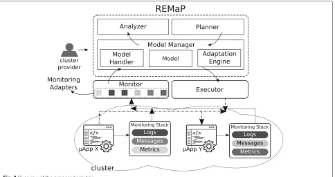
three main steps: to monitor the system under manage-ment, to make a decision based on monitored data, and to execute an adaptation plan taking into account the decision. Figure3overviews our solution.
5.1 Design overview
Upgrade events of theμApp trigger the adaptation pro-cess. The adaptation repeats indefinitely at regular time intervals. When the code of one or more microservices changes, i.e., developers push new code into the reposi-tory, theAdaptation Manager listens for this event and starts the adaptation. The push command should be labelled with the time interval in which REMaP waits between the adaptations.
The first step of the adaptation is to collect data about
the μApp. TheMonitor inspects theμApp through the
Monitoring Adapters. The adapters abstract away different monitoring technologies to gather useful historical data, such as resources usage and microservices interactions (μApp workflow). TheMonitorgathers data according to the time interval set in the adaptation bootstrap (e.g., if the time interval is 10 minutes, the Monitorgathers all data generated in the last 10 min.) REMaP takes collected
data and populates the application Model. The Model
organizes the data for the μApp, building up its topol-ogy, filling up each representation of the microservices in the model with their historical data, such as the average of CPU and Memory consumption in the time interval, and linking the microservices according to the messages exchanged.
Next step is the model analysis. TheAnalyzerinspects the model looking for interactions between microservices to compute their affinities. TheAnalyzerstores the affini-ties in the model, in such way that thePlannercan access them.
Once the affinities are available, thePlannercan com-pute the adaptation plan. ThePlanneruses the affinities and resource usage stored in the model to calculate a new placement plan (adaptation plan) for the microservices.
In this scenario, the adaptation means the optimization of the microservice placement. The optimization relies on two dimensions: microservices’ affinities and resource usage history. Considering these dimensions, thePlanner
computes a deployment plan to reduce the resource usage and communication latency while minimizing the impact on the application performance.
Traditional approaches to the Bin-Packing problem try to minimize the number of bins used considering the number of items available and their respective values (see Section4). In contrast, the optimization of microservice placement also includes the concept of affinity, so that the value of an item (microservice) varies according to the other items in the bin where it is assigned. This feature increases the complexity of the problem. Hence, in addi-tion to the minimizaaddi-tion of resource usage, we also aim to maximize the affinity score of the selected hosts, i.e., plac-ing the maximum number of highly-related microservices together.
Finally, the Adaptation Manager applies the
adap-tation on the Model and checks the consistency of
changes before consolidating them in the runningμApp. The Adaptation Manager forwards to the Executor the changes that do not violate the model.
TheExecutorconsolidates the changes in theμApp by translating the actions defined in the adaptation plan and applied to the model into invocations to the management tool API.
The rest of this section details all of the components introduced above.
5.2 Model
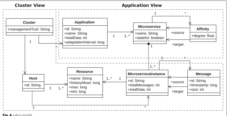
TheModelshown in Fig.4abstracts and allows the inspec-tion and analysis ofμApps at runtime. As mentioned in
Section3.2, we use [email protected] concepts to make
viable the use of a unique artifact and reduce the semantic gap between technologies used to monitorμApps.
TheModelabstracts essential elements of theμApps in a cluster. This model is inspired by the evolution model proposed in [4] and includes the concept of affinity. In this work, the model acts like afacadeto simplify and unify the interfaces provided by different monitoring tools.
ClassMicroservicemodels a microservice and includes the name and an indication whether the
microser-vice is stateful or not. Class MicroserviceInstance
is a specialization of class Microservice and
repre-sents a microservice instance, i.e., a μApp includes
different kinds of microservices and each type of microservice can have multiple replicas (microservice instance). A microservice instance has the total num-ber of messages and data exchanged by a microservice replica.
Class Message models the communication between
μApps, and represents the edges in theμApp graph. Every message has a unique id, response time, timestamp, and size. The set of messages describes the workflow of the μApp.
ClassAffinitymodels the communication between two
different microservices (not their replicas) considering the number of messages and amount of data exchanged. The affinity has a degree that represents the strength of the relationship between two microservices.
ClassClusterabstracts the management tool used and
maintains the hosts available in the cluster. In turn, each classHosthas a set of microservice instances.
Finally, hosts and microservice instances haveResources
attributes that maintain the information of the usage his-tory, e.g., CPU and memory mean usages (history) of hosts and microservices, and resources limits. Figure 5 shows how aμApp is represented at runtime by our model, and it highlights theμApp architecture (application view) and theμApp deployment (cluster view).
The cluster view models how the μApp is deployed
across several hosts and the use of resources by hosts and microservices. Moreover, this view shows the communi-cation topology and messages exchanged by the microser-vices. The cluster view is volatile as microservices replicas frequently come up and go at runtime.
The application view models the architecture ofμApps running in a cluster and highlights the microservices that make up the application. This view also shows affinity links between microservices; this view is more stable than the cluster view since microservice upgrades are less often than microservices scaling.
The separation of application and cluster concerns cre-ates a more expressive model. It allows the analysis and adaptation actions to be performed individually on the
μApp or cluster without needing to inspect the whole
model. For example, theAdaptation Managercan use a
fresh configuration to compute the adaptation plan (clus-ter view), while theExecutoruses cluster information to guarantee that only safe changes will be applied on the μApp (application view).
5.3 Monitoring
Fig. 4μApp model
theAdaptation Managerand consequently triggering too many adaptations.
Component Monitoring provides a standard way to
retrieve data independent of monitoring technologies used in the cluster. This component is passive (only returns data in response to a request) and aggregates all data necessary to compute the adaptation plan. In
prac-tice, theModel Managerused information monitored to
update the runtime model.
EveryμApp has a monitoring stack to collect data. Usu-ally, the monitoring stack collects three different kinds of data: resources usage, execution logs, and exchanged messages. The monitor maintains a global view of the environment by gathering information from the manage-ment tool being used (e.g., Kubernetes or Docker Swarm), host and microservice resource usages, and events gener-ated by DevOps operations, such as updates to the code repository and microservices deployment. The numeric data, usually related to resources usage, are aggregated as the average of instantaneous values measured from the μApps components. For instance, this average can repre-sent the history of CPU usage of a microservice in a given time interval.
Monitoring tools collect data and store them in differ-ent data stores continuously. The monitor abstracts these data stores by using clients responsible for retrieving and transforming these data into agnostic structures used for populating the model.
Finally, the monitoring provides data according to var-ious aspects such as resources metrics, messages, logs,
and events. For each of these, the monitoring component allows sampling of the data over a given period.
5.4 Analyzer
The Analyzer component, shown in Fig. 3, is designed to process the model at runtime by looking for
affini-ties between microservices. We define affinity between
two microservices using the number of messages and the amount of data exchanged between them. We use a ratio (weight) in the affinity calculation to steer the Analyzer
execution. The data exchanged by the microservices are not equally distributed among all exchanged messages. It may existμApp workflows with few messages and a large amount of data and vice-versa. Hence, a high ratio value (ratio> 0.5) leads theAnalyzer to value the number of messages over the amount of data. A small value (ratio <0.5) does the opposite, and a ratio of 0.5 balance the two attributes equally.
TheAnalyzercomponent detects unexpected behaviours not perceived by application engineers. Different analyz-ers can be implemented and plugged into the adaptation mechanism, depending on the analysis needed. In this work, we design anAffinityanalyzer that detects affinities
between microservices. As mentioned in Section 4, the
affinity is used to optimize theμApp placement.
The analyzer checks the messages exchanged by the
μApp (stored in the model) and calculates the
Fig. 5Instantiation of the model
types of microservicesaandbasAa,band calculate it as
follows:
Aa,b= ma,b
m ×w+
da,b
d ×(1−w), (1)
where,
– m is the total of messages exchanged by all microservices,
– ma,bis the number of messages exchanged between microservicesa and b,
– d is the total amount of data exchanged by all microservices,
– da,bis the amount of data exchanged between microservicesa and b,
– w is the weight, such that{w∈R|0≤w≤1}, used to define which variable is the most important to compute the affinity, i.e., number of messages or amount of data exchanged.
Finally, in addition to synchronous communication through REST APIs, the microservice architecture com-monly uses asynchronous communication through Pub-Sub protocols. REMaP can compute an optimization for μApps using async communication since, like data stores, the messaging middleware (e.g., RabbitMQ) is wrapped into a container. In this case, the analyzer can identify which microservices have a high communication rate and may co-locate them with the middleware. However, if
theμApp outsources the messaging middleware, REMaP
cannot correctly calculate microservices affinities, and consequently, no placement optimization may be applied.
5.5 Planner
ThePlannercomponent decides how to apply the adapta-tion to theμApp. Similarly to the analyzer, different plan-ners can be implemented and plugged into the adaptation mechanism, depending on the adaptation strategy.
We propose twoPlannersto compute the placement of
microservices during an adaptation: theHeuristic-based Affinity Planner(HBA) and theOptimal Affinity Planner
(OA). Both planners compute a new placement forμApps
by reducing this problem to a multi-objective bin-packing problem. As this problem is NP-Hard, we know that for large μApps an optimal approach is infeasible. Hence, we implement the heuristic version (HBA) to achieve approximate solutions for largeμApps and the optimal version (OA) to achieve an optimal solution for small μApps.
Both planners access the model to obtain information about the resource usage history and affinities between microservices to compute the adaptation plan. It is worth noting that the planners do not use instantaneous values of the metrics. Instead, they use historical data maintained in the model. This approach provides more reliable limits (max and min) on the resource needs of each microser-vice.
Finally, both planners can handle stateful microservices and data stores, since the data stores are also wrapped into microservices. However, REMaP cannot handle data sync across different hosts after migrating a stateful microser-vice. Hence, the migration of stateful microservices may lead theμApp into an inconsistent state.
5.5.1 Heuristic-based Affinity Planner (HBA)
The heuristic planner (HBA) reorganizes the placement of microservices that make up a μApp in a cluster. The planner computes how to rearrange the microservices so that microservices with high affinity are co-located, while microservices’ resource usage and availability of resources at the host are taken into account. This plan-ner is inspired by the First-Fit [9] approximation algorithm (see Algorithm 1) to compute the list of movements nec-essary to reconfigure theμApp.
Algorithm 1 iterates over the affinities and tries to co-locate the microservices associated with them. For each pair of microservices mi,mj
linked by an affinity, the algorithm attempts to placemjonto the host ofmi(Hi). If Hidoes not have enough resources, the algorithm tries to
putmionto the host ofmj
Hj
. If both hosts do not have enough resources to co-locatemiandmj, these
microser-vices remain at their original hosts. When a microservice is placed into a new host, it is marked asmovedand can-not move anymore, even if it has an affinity with other microservices. In the end, a list of movements is gen-erated containing microservice identities and their new locations.
This algorithm does not guarantee that the list of moves computed is optimal for a cluster given a set of microser-vices.
Algorithm 1:Variant of the First-Fit algorithm to move microservices.
1 moved←[ ]
2 // affinities are in decreasing order 3 forall thea∈affinitiesdo
4 // r(m) gets the microservice usage resources 5 // r(H) get the amount of free resources in host H 6 // Microservices mi,mjhave affinity a
7 mi∈Hi// milocated at host Hi 8 mj∈Hj// mjlocated at host Hj 9 Hi=Hj
10 hasMoved←false 11 ifr(mi)+r
mj
≤r(Hi)∧mj∈/movedthen 12 Hj←Hj−mj
13 Hi←Hi∪mj 14 hasMoved←true 15 end
16 else if r(mi)+r
mj
≤rHj
∧mi∈/movedthen 17 Hi←Hi−mi
18 Hj←Hj∪mi 19 hasMoved←true 20 end
21 ifhasMovedthen
22 moved← moved∪mi,mj
23 end 24 end
5.5.2 Optimal Affinity Planner (OA)
Planner OA optimizes the placement ofμApps. Given a
Maximize:
(ji,jk,score)∈A,n∈Hosts
if pji,n
∧pjk,n, score, 0 (2)
Subject to: Hosts
n
pj,n =1 forj∈Microservices (3) ⎡
⎣Microservices
j
if p(j,n),M(j), 0 ⎤
⎦≤M(n) forn∈Hosts
(4) ⎡
⎣Microservices
j
if p(j,n),C(j), 0 ⎤
⎦≤C(n) forn∈Hosts
(5)
Where:
– Microservices is the set of microservices to be deployed,
– p(j,i)is true if microservicej is placed on host i, – A⊂Microservices×Microservices×Nassociates an
affinity score to a pair of microservices, – Hosts is the set of hosts available for placing
microservices,
– M(j)is the memory required by microservicej, – M(n)is the memory available in hostn,
– C(j)is the number of cores required by microservice j, and
– C(n)is the number of cores available in hostn.
Equation2 defines the objective function, maximizing the sum of affinity scores of all co-located microservices
ji,jk. This equation returns score if p
ji,n
∧ pjk,n
evaluates to true and 0, otherwise.
Equation3is a constraint enforcing that each microser-vice is placed on precisely one host. For each microsermicroser-vice, the sump(j,n)over all hosts must be 1, meaning that for each microservicej,pmust be true exactly once. Note that while a microservice can only be placed on one host, a host may have multiple microservices placed on it. Equations4
and 5enforce that each host has sufficient memory and
cores for executing the microservices.
This planner tries to minimize the number of hosts used to deploy aμApp and maximize the affinity scores on each host. In practice, this algorithm places microservices with high affinity together, considering the host resources and the microservice resource usage history.
Unlike the HBA planner, the OA planner is guaran-teed to find an optimal placement, i.e., oen that minimizes wasted resources.
5.6 Executor
Component Executor, shown in Fig. 3, is designed to
apply the adaptation plan computed by thePlannerin the μApps safely. AsμApps are constantly changing, an adap-tation that was computed but has not been yet applied could be unsafe to apply due to external factors. As the
Modelis causally connected, if the application is upgraded and has part of its architecture changed, the model reflects its new configuration. Hence, theExecutorvalidates the
change on the Model before applying the change to the
μApp. If the change is no longer valid, then it is discarded. The Executor component essentially translates high-level commands defined by the planner as low-high-level prim-itives of the management tool. Hence, an executor is necessary for each management tool.
The executor first checks whether it is possible to move a microservice from one host to another in the model or not. In some situations, the executor cannot perform this movement. For example, assume that microservices A and B have two instances, A.1 and A.2, and B.1 and B.2, respectively. Besides, A.1 and A.2 have high affinity with B.1 and B.2 as well. As mentioned in Section5.4, the ana-lyzer checks in the model that the microservice of type A has high affinity with B. Also, suppose that the planner has computed that A.2 should be co-located with B.2, but at runtime, A.2 has been de-allocated due to an unexpected scale-in action. Therefore, the movement to co-locate A.2 with B.2 becomes invalid.
By only using valid movements guarantees that only safe changes occur in theμApp. If the movement is valid, the executor attaches the microservice to the destination host and unsets this microservice from the source host.
Finally, the executor deals with microservice instances that come up during the adaptation process. Once the model has the microservices linked by the affinities, the executor can use this information to drive where the new replicas will be placed. For example, given two microser-vices A and B with high affinity. Initially, there might be only replicas A.1 and B.1. However, during adaptation to co-locate A.1 and B.1, the microservice B scale out, and a B.2 replica is generated. The Executor will check the model and find the affinity between A and B. First the
Executor will attempt to co-locate B.2 with A.1, but it rechecks the model, and the host where A.1 is placed does not fit another replica of B. So, the executor will try to co-locate B.2 with another microservice such that both of them have an affinity. If such microservice does not exist, the executor maintains replica B.2 at the host where it was instantiated.
5.7 Model manager
TheModel Manageris the core component of REMaP. It implements the causal connection between the model and
In essence, the model manager triggers the adaptation by coordinating the MAPE-K elements, and by maintaining the model at runtime.
TheModel Managerhas two key elements:Model Han-dlerandAdaptation Engine(engine). The model handler populates the model using data collected by the moni-tor. At runtime, the model is represented as a graph (see Fig.5), and the model handler performs changes on this graph, e.g., the inclusion of affinities, and microservices moves.
The adaptation engine coordinates the actions of the MAPE-K components and provides an interface to add new analyzers and planners. Moreover, this engine trig-gers the adaptations. In this paper, the adaptation per-formed is the placement optimization applied to the microservices. The adaptation is triggered in timed
inter-vals set by the μApp engineer, and each μApp has its
timer. However, when theμApp is upgraded (e.g., new
versions of its microservices are deployed), the timer is reset to wait for this new version generates enough data to populate the model. When the time interval is reached, the control loop is started. The analyzer calculates the affinities, updates the model, and notifies the planner. The planner uses the affinities to compute an adaptation plan. The planner sends the adaptation plan to the executor that migrates the microservices.
The causal connection has two steps. In the first step, known asreflection, REMaP receives data collected by the monitor and uses it to create the model. In the second step, thereification, REMaP consolidates the changes to the model into the executingμApp through the executor.
6 Implementation
6.1 Monitoring
We implemented theMonitoringcomponent (see Fig. 3)
to collect data from Influxdb18and Zipkin19.
Influxdb stores resource information from the microser-vices and hosts. Heapster, a Kubernetes plug-in20, collects resource usage information of microservices and hosts. It inspects microservice containers and hosts, and stores CPU and memory metrics into Influxdb.
Zipkin is a distributed tracing system to collect mes-sages exchanged between microservices. Developers have to instrument the microservice with code snippets informing which messages Zipkin needs to capture. Once collected, Zipkin stores and makes them available via an API.
We also implemented a Kubernetes client to collect signals from the cluster and cluster configuration. Kuber-netes has an API that provides cluster data such as avail-able hosts and running microservice instances. This data is used to populate the model as illustrated in Fig.5.
Each monitoring component wraps the underlying monitoring technology and exposes some interfaces:
MetricsInspectionInterface provides information about
resources usage, MessagesInspectionInterface gives
information about exchanged messages, and
ClusterIn-spectionInterface stores information about cluster data and organization, e.g., hosts and running microser-vice instances. These interfaces are combined into a
InspectionInterfaceexposed by the monitoring.
Finally, the monitor also implements a listener to handle DevOps events. The listener receives events from Travis. Travis21is a continuous integration tool that signals when a new deployment event occurs, such as upgrading a
μApp. Hence, when engineers upgrade the μApp, this
listener resets the timer in the adaptation engine, as described in Section5.7.
6.2 Analyzer
As presented in Section5.4, the affinity analyzer retrieves information about messages exchanged by the microser-vices from the runtime model and calculates their
affini-ties using Eq.1. Our analyzer uses the EMF framework
to look up the elements in the model. The EMF
frame-work22 has inner mechanisms to transverse the model
transparently. Hence, the analyzer only looks up elements by their types, in this case, lookup for message types.
After calculating the affinities, the analyzer generates two lists of affinities. One is a sorted list that the analyzer dispatches to the planner. Another list is aggregated, by summing affinities of the same type of replicas into one affinity.
6.3 Planner
The planner computes the movements to optimally re-arrange the microservices. It creates a list of moves to transfer a microservice from one host to another and passes this list to the model manager. Then, the model manager forwards the list to the executor.
As mentioned in Section5.5, we implemented two plan-ners: HBA and OA.
6.3.1 HBA Planner
This planner goes through each affinity generated by the analyzer and checks if it is possible to move one of the microservices, as defined in Algorithm 1. If the movement is valid, then it is stored in the Adaptation Script. It is worth observing that only stateless microservices can be
moved. As mentioned in Sections3and4, the movement
of stateful microservices can raise issues onμApps execu-tion. Hence, we decided to add this constraint to planner HBA.
In this case, a movement is computed to move A.1 to H.b. If both microservices neither fit on H.a nor H.b, then this affinity is discarded, and the planner tries the next affinity. The HBA planner only moves microservices to hosts where they already execute. In this example, microservices A.1 and B.1 can only be moved to hosts H.a or H.b.
After passing over all affinities, the planner forwards an
Adaptation Scriptto the executor.
6.4 OA Planner
Planner OA computes the placement of microservices using an SMT solver to calculate the optimal arrangement of microservices in such a way that minimizes the number of used hosts and maximizes the affinity scores for each host.
Our implementation uses the Z3 SMT solver23. The
optimization is modelled as a satisfiability statement [23] that can return the optimal placement to a given input. However, SMT solvers usually use brute force to compute an optimization. Hence, as the placement of microser-vices is an NP-Hard problem, SMT solvers are unable to calculate an optimal placement for large instances of this problem.
Planner OA transforms the SMT solver output into a list of moves like move(microservice, source=host, tar-get=host). Next, it sends the list to the model manager that forwards it to the executor.
Unlike HBA planner, OA planner can move A.1 and
B.1 to hosts other than H.a and H.b. Furthermore, the
current implementation ofplanner OAcannot
differen-tiate stateless and stateful microservices. As OA planner must create a satisfiability formula for all attributes used to compute an adaptation plan (microservices affinities and metrics of CPU and memory), adding a dimension increases the difficulty of calculating an optimal adapta-tion plan exponentially, even for smallμApps, e.g., less than 12 microservices. Hence, we choose not to use this constraint in the computation of the adaptation plan.
6.5 Executor
The executor has an engine that identifies the kind of adaptation plan received from the planner and executes it automatically.
Similarly to the monitor, the executor also provides wrappers to existing management tools. When the execu-tor receives the adaptation plan, it applies the moves one-by-one on the model. If a move cannot be applied, as discussed in Section5.6, it is discarded. Otherwise, the move is sent to the management tool wrapper that applies it to the μApp. Currently, the implementation includes wrappers for Kubernetes and Docker Swarm.
In Kubernetes, the wrapper applies the changes by updating how the microservices are attached to the hosts
in the deployment description maintained at runtime by Kubernetes. Kubernetes goes through all services updat-ing their placement attribute. Next, it executes the update, e.g., it creates a replica of the updated microservice in a new host, starts the microservice and automatically removes the old one.
Docker Swarm wrapper works similarly. However, unlike Kubernetes, Docker Swarm first removes the pre-vious microservice and then creates a new replica in the new location.
It is worth observing that, in both wrappers, if the executor detects a failure after applying the changes, the adaptation process stops, and the change is undone in both theμApp and model.
6.6 Model manager
REMaP (see Fig.3) wraps the Model Handler and Adapta-tion Engine maintains the Model at runtime, and connects all MAPE-K related components.
REMaP coordinates the MAPE-K components through its built-in messaging mechanism. The Monitor sends col-lected data to the Model Manager that dispatches them to the messaging mechanism. The Model Handler is respon-sible for building up the Model. When the Model Handler builds the model, it signals the Analyzer that must evalu-ate it. Next, the Analyzer signals the Planner to compute the adaptation plan, i.e., it generates the adaptation script. Finally, the adaptation script is delivered to the Executor that carries out the adaptation. All signals are received and dispatched via the messaging mechanism.
The Model Handler also uses the EMF framework
to maintain the model at runtime. EMF abstracts the
construction/traversal of the model and provides a robust notification mechanism to notify when the model changes, signalling these changes to other components. In our implementation, theModel Handlercaptures these signals to update the number of messages and total data exchanged between the microservices.
When amessageis attached to a microservice instance, EMF signals to the Model Handler that the model was updated. The signal includes the message attributes. The EMF notification uses actuators to update the microser-vice instance automatically by counting the new message attached to it and the message size. Once the microservice instance is updated, EMF signals to the Model Handler that the microservice was updated. Recursively, the EMF notification mechanism updates the application, count-ing the total number of messages exchanged by the whole μApp and the total amount of data exchanged.