Journal of
Engineering Innovation
And Research
Volume: 1, Issue: 1
Improving Nickeling Process through Value Engineering Technique
Chinmay Das*
Value Engineering is a systematic step by step methodology for continuous improvement of products, process, service and system. Nickeling is widely done on many industrial and consumer products for protection and better appearance. In this paper detailed analysis has been done on how VE can be
applied for improvement and cost reduction of nickeling process.
Keywords: Value, Function, Worth, FAST Diagram, Decision Matrix
INTRODUCTION:
M/s Subhalaxmi Products situated at Bhubaneswar has been producing nickel coated products like paper pins, gem clips, stapler pins, cycle spokes etc. for a number of years. The organization is a leader in supplying cycle spokes of varying sizes to local market. Presently it is loosing the market share. The reason for the same being the shorter time period of the product’s useful life. This problem is considered to be a good candidate for Value Engineering analysis.
Objectives and Scope of the project:
1. Prevent corrosion of cycle spokes within the useful life.
2. Provide a better product at lower cost. 3. Minimum change over investment.
INFORMATION PHASE:
The nickeling process was studied in detail and the flow chart was prepared.
Process Description
1. Cleaning: The purpose of cleaning prior to plating is to remove all interfering substances from the surface to be plated. Adhesion, smoothness and corrosion resistance of nickel plate depend on a proper cleaning cycle. Any foreignsubstance which _________________________________________
* Asst.Professor, ABIT, Cuttack E-mail: [email protected]
separates the coating from the subsurface decreases the adhesion. Generally acid pickling is used for this purpose. In this process, the material is dipped into dilute hydrochloric acid for 15 minutes. The oxide scale and inert materials are removed from the surface of the parent material. After that sulfuric acid wash is done by dipping in dilute sulfuric acid for about 20 minutes.
2. Polishing: After pickling, wood polishing is done to remove any traces of rust or other particles present on the surface of the job.
3. Caustic Soda Wash: This treatment is given to remove any trace of acid on the surface of the job. 4. Buffing: The completely cleaned surface is then buffed to have good surface finish. This is important because the surface finish of base metal governs the final surface finish of the coating. 5. Nickeling: Nickel is electroplated by dipping materials in electrolytic bath. The bath is a mild steel rectangular container of thickness 40 mm with a size 2m, 1m and 0.6m. Moderately concentrated solution of nickel sulphate, nickel chloride (450 g/l), some boric acid (40 g/l), little H2O2 and
ammonium chloride are taken in the bath. The pH value ranges from 3.8 to 4.2. Nickel anode of 90% nickel, remainder being iron, carbon, silicon and manganese, is used. The cathode and the anode are connected with a rectifier for direct current supply.
Figure 1: Flow Chart of Nickeling Process
Cost Analysis: The costs for various processes were presented here.
Sr.N o.
Item Present Cost
in Rs.
1 Pickling & Washing a) Acid 330Kg @ Rs.6/Kg b) Water
c) Caustic Soda 33Kg @ Rs.18/Kg
1980
30
594
2 Polishing & Buffing 2500
3 Nickeling a) Nickel sulphate 11 Kg @ Rs.180/Kg b) Nickel chloride 6 Kg @ Rs.225/Kg c) Boric acid 3.5 Kg @ Rs.80/Kg d) Other chemicals e) Electricity 1660 units @ Rs. 2.75/unit f) Water g) Nickel anode 125 Kg @ Rs. 66/Kg 1980
1350
280
300
4565
400
8250
Total 22229
Table 1: Cost Analysis of Nickeling Process
Sr.No. Item Percent
Cost
1 Pickling 11.76 2 Polishing 11.24 3 Nickeling
a) Nickel b) Electricity c) Other
37.11 20.00 19.89
Total 100.00
Table 2: Cost Break up of Nickeling Process
The cost of nickeling alone was approximately 77% of the total cost of the entire process. This meant that nickeling itself is required a very detailed study. It was also observed that cost of nickel and electricity contribute 37 and 20 percent respectively to the total cost of the process.
FUNCTION PHASE
:
For the purpose of identifying the function involved in the total process, the functions of three major parts of the process were considered.
a) Pickling and Washing: The main function of this step in the process was to “remove scales” b) Polishing and Buffing: The function of this step in the process was to
“prepare surface” of the jobs so that the nickel coating adhered well to the surface.
c) Nickeling: The function of this step was to “provide coating”. Electricity is consumed for electro deposition of metal. So it does “provide energy” function. Nickel gives “coat spokes” function.
Unpickled
Jobs
Pickling
with Acids
Polishing
Buffing
Nickeling
Final
Buffing
Finished
Jobs
How?
→
←
Why?
←
---Scope Line---
→
Figure 2: FAST Diagram for Nickeling Process
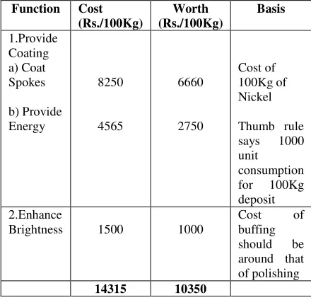
Function Cost (Rs./100Kg)
Worth (Rs./100Kg)
Basis
1.Provide Coating a) Coat Spokes
b) Provide Energy
8250
4565
6660
2750
Cost of 100Kg of Nickel
Thumb rule
says 1000
unit consumption
for 100Kg
deposit 2.Enhance
Brightness 1500 1000
Cost of
buffing
should be
around that of polishing
14315 10350
Table 3: Function-Cost-Worth Analysis Value Potential = Cost-Worth
= 14315-10350 =Rs. 3965/ 100 Kg
CREATION PHASE
:
The following points were observed in nickeling process.
1) For 1 Kg deposit of nickel, the consumption of nickel anode is 1.25 Kg (approx.).
2) Time of nickeling process is also high.
3) Coating is neither uniform nor free from porosity.
The various reasons for the products getting corroded inspite of nickel coating can be summarized as
i) The coating was brittle and had significant porosity. Nickel has fewer tendencies to corrode compared to steel. At the porous portion of coating, iron would be exposed to environment and would corrode rapidly compared to nickel. Therefore rust would appear on the surface. In order to prevent corrosion of iron, nickel coating should be continuous without any crack.
ii) The cycle spokes were subjected to cyclic loading. If tensile residual stresses were present in nickel coating, it would produce cracks due to surface failure. At those locations iron would corrode. In order to prevent this, the coating of nickel must be free of residual stresses.
iii) Transfer of loose particles like nickel, nickel oxide, carbon etc. to the cathode would interfere with proper coating of nickel on the surface.
Enhance Appearance
Improve Brightness
Satisfy Customer
Protect Spokes
Exclude Oxygen
Provide Coatings
Prepare Surfaces
Remove Scales
Impurities accumulated in the bath can have deleterious effect on the quality of nickel deposit. The greases, waxes, dust and resinous substances may promote pitting and brittleness.
Taking all the above mentioned factors into consideration, the required nickeling process must give
a) Uniform porous free coating b) High speed operation
c) Low wastage of anode materials
d) No detrimental residual stress in the coating
e) Low cost of operation
Since no existing electrolyte bath can satisfy all the above objectives, it was decided to develop some innovative alternatives. Two proposals were developed.
1) Proposal number 1:
Instead of thick nickel coating, multiple layer different materials deposit are to be made. At first a copper under coat of 0.005mm is provided. Then nickel coating of 0.015mm thickness is made over it. Finally chromium coating of 0.01 mm is done. This multi layer coating prevents formation of pits & pores.
Corrosion resistance is greatly increased. Chromium coating provides excellent lustrous appearance. Since chromium outer layer has high hardness and strength, therefore surface failure will not occur under cyclic loading.
Use of high purity nickel anode (99% Ni). This anode is passive in low chloride cold bath. But with the use of moderate chloride high temperature electrolyte bath, high purity nickel anode can be used.
The cotton bag is to be placed around the anode which will prevent escape of nickel dust and nickel oxide to the solution.
If the cathode efficiency is low, then significant amount of nickel ion will
form salts in the solution. These salts are loss of nickeling process. Increased temperature, more chloride and nickel ion concentration, increased current density increased pH provide more metal deposition.
The composition of electrolyte bath is Watt’s type with some modification.
Nickel Sulphate Nickel Chloride Boric Acid Temperature Current Density pH
330 g/l 45 g/l 38 g/l 46-600 C 3-11 mA/ cm2
1.5-4.5
Table 4: Modified watt’s Bath
Agitation of bath to be made by mechanical means like paddles or compressed air.
Proposal number 2:
In this proposal, the composition of electrolyte bath and the process variables like temperature, current density, pH, concentration of ions are to be modified. The characteristics of electrolyte bath will be intermediate of Watt’s type and bright nickel type bath. This is called semi-bright nickel bath and the coating formed possess excellent buffing properties together with acceptable ductility and good scratch hiding properties. The semi-bright plating allowsa marked reduction in the cost of buffing labour and materials. In addition, the smaller amount of material removed lowers the nickel plating cost because less plating is required before buffing. The plate has good scratch covering power, plus good flowing ability under the buffing wheel, the quality of base metal polish may be lower.
Nickel Sulphate Nickel Chloride Boric Acid
Brightener(class-1 & class-2) Wetting agent
(Sodium Lauryl Sulphate)
Temperature Current Density
pH
400 g/l 60 g/l 38 g/l 2-4 g/l
1 g/l
40-500 C 1-8 mA/
cm2 3.0-4.5
Table 5: Electrolyte Bath for Semi-Bright Nickel Coating
EVALUATION PHASE
:
The following criteria were selected for evaluation of the proposed solutions.
They are
A. State of the art technology level B. Cost of development
C. Durability D. Reliability
E. Potential cost benefit F. Safety
B C D E F
A
B
C
D
E
Major Difference: 3 Medium Difference: 2 Minor Difference: 1 No Difference : 0
Figure 3: Paired Comparison Matrix
At this stage the points for each criterion were added numerically and tabulated.
Identity Criterion Score
A B C D E F
State of the art Cost of development Durability
Reliability
Potential cost benefit Safety
1 0 5 2 7 1
Table 6: Weightage for criteria
The proposals were evaluated on a 1 to 5 scales as given below against each of the criterion to decide the priority of the ideas for implementation.
Excellent-5, Very Good-4, Good-3, Fair-2, Poor-1
The points for each criterion are written in the top left hand corner of the corresponding block, as shown above. These points are then multiplied by the weightage decided earlier for the criterion and the score is written on the bottom right hand corner of the block. All such scores for the individual alternative are summed up and entered in the extreme right total column. The total scores for the various alternatives decided the final ranking of the proposals.
A B C D E F Alternate
Proposal
Weightage
for criteria 1 0 5 2 7 1
Total Score 2 3 1 1 2 2
Existing Method
2 0 5 2 14 2 25
3 2 3 3 2 2 Proposal No.-1
3 0 15 6 14 2 40
3 3 4 3 3 2 Proposal No.-2
3 0 20 6 21 2 52
Table 7: Decision Matrix
RECOMMENDATION PHASE:
Out of above two proposals, proposal no.2 was selected and recommended for
implementation.
REFERENCES:
1. BARLOW, Christoper M., “Doing Value Engineering”, Journal of Co-creativity Institute, 1999, page 47-49.
2. BURNS, R.N. & BRADLEY, W.W., “Protective Coatings for Metals” Reinhold Publishing Corporation, Chapter 5.
3. FALLON, Carlos, “Value Analysis to Improve Productivity”, 1971, Wiley-Interscience, Chapter 3.
4. JAGANNATHAN, G., “Getting More at Less Cost”, TMH, 1992, Chapter2, 3, 4.
5. MILES, Lawrence D., “Techniques of Value Analysis and Engineering”, 1972, Mc Graw Hill