Analytical Study of Funicular and Flat Slabs
V. D. Santosh Kumar A. Uma Maheswari
M. Tech. Student Assistant Professor Department of Civil Engineering Department of Civil Engineering
Chaitanya Engineering College, Andhra Pradesh, India Chaitanya Engineering College, Andhra Pradesh, India
Abstract
A funicular slab is a thin doubly curved shell of a shape which is purely in compression in most parts of the shell. In funicular shells, the shape of the shell is such that under a particular loading condition, the shell is subjected to pure compression unaccompanied by bending and shear stresses. The shells are subjected to pure membrane state of stress, under appropriate loading and boundary condition the resulting bending and twisting moment are either zero or small which may be neglected. In this study doubly curved thin shells are analyzed using finite element software SAP 2000. Doubly curved shells which are in square plane having 3m*3m are considered. The behavior of shells under uniformly distributed load is studied and compared with the plane flat slabs of same dimensions and thickness. In this case study deflection curves, membrane stress contour diagram are obtained. It is observed that the deflections, bending moments and shell stresses of funicular shell are reduced when compared to flat slab. Keywords: Funicular slab, doubly curved thin shells, waffle shells
________________________________________________________________________________________________________
I. INTRODUCTION
General
Precast doubly-curved shells (Funicular shells) have been in use for the past few years as roofing and flooring elements. These shell units are effectively used for replacing the solid RCC slabs. They may be used in conjunction with precast joists or battens or planks or as waffle shells by providing ‘in situ ribs in two directions. This type of construction has many advantages over the conventional RCC slabs being lighter in weight and saves reinforcing steel and concrete.
Concept of Funicular Shell
A Funicular Shell is a three dimensional catenary on a rectilinear base. The roofing system consists of doubly curved shells made with materials of good compressive strength such as waste stone pieces and brick tiles and supported on reinforced concrete edge beams. A series of these shells in variable geometric configurations supported on a grid of concrete beams, identical to a coffer slab, provides an attractive roof for small to medium spans.
Conceptually, a funicular structure could be said to be a structure which can achieve equilibrium state by adopting a mechanism of a 'right' form (shape/geometry) corresponding to the applied loads. This ‘right’ form is referred to as the ‘funicular’ geometry. Medieval vault builders created complex forms carefully balanced in compression. For example, a catenary cable is a ‘funicular’ geometry for uniformly distributed loads. Under any other loading pattern, this shape is non-funicular, as the cable mechanism needs to move considerably to find an equilibrium state.
Architecturally, funicular designs result in highly efficient integral structural design and opens up a whole new design vocabulary. Funicular design forms seem natural and impart certain lightness to the structure.
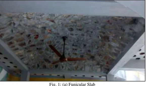
The shapes of these shells are chosen that, under UDL, in a membrane state of stress, they develop only pure compression unaccompanied by shear stress. Thus no reinforcement is necessary, except in the edge members. In the lower portion steel reinforcements are required to counter the tensile stresses. It can be converted as compression structure by inverting it, with a considerable reduction in the quantity of steel & cement. Compression structures are used in the form of vault, arches, domes and doubly curved thin shells also known as funicular shells are widely used in the construction of forts and temples. These structures are the best proof for the durable performance of shell structures. The funicular shell roof structure is one such compressio n structure, which can be built by utilizing waste materials and natural resources can be conserved effectively and use of expensive steel and cement are optimized. Diagonal grid of funicular shell gives the resemblance of a largest space. A typical view of funicular shells used for a roof construction is shown in figure 1(a).
Fig. 1: (a) Funicular Slab
In this project we will be discussing about the “Analysis of a funicular shell” compared with normal “flat slab” of the same dimensions. For the analysis and design of these structures we have used SAP 2000 v 20 software which is exclusive for the analysis of structures.
SAP 2000 v 20 Software
SAP2000 is a stand-alone finite-element-based structural program for the analysis and design of civil structures. It offers an intuitive, yet powerful use interface with many tools to aid in the quick and accurate construction of models, along with the sophisticated analytical techniques needed to do the most complex projects.
II. LITERATURE REVIEW
The behavior of prefabricated shell units has been investigated, both theoretically and experimentally, by many researchers. Abolhassanvafai, Massoudmofid and HomayoonE.Estekanchi (1997) have done an experimental study on prefabricated funicular shells. Along diagonal of the sections experimental values and theoretical values of membrane stresses are compared. The results were similar to the theoretical results.
Experimental results of vertical deflections along the transverse sections & longitudinal sections of the shells also favorable with the theory. Experimental failure and crack loads are found & empirical equations, expressing the relation between rise & failure crack loads, are given. Based on the design forty five models were constructed. Apart from construction schemes, the use of pre-fabricated shell units creates certain problems which have to be investigated from the research point of view. One of the most important is the structural behavior of the units when subjected to the concentrated loads at various points along their span. Another consideration of interest is the ultimate strength and pattern of failure for these types of shells. The shells of double curvature usually offer a higher ultimate strength than the shells of single curvature, such as cylindrical shells. The funicular shell roof is one such compression structure, which ensures conservation of natural resources by utilizing waste materials effectively and optimizing the use of expensive steel and cement.
load. Failure patterns for shells with both kinds of reinforcement were the same. They observed that the mathematical investigations of shallow funicular shells with large concentrated loads should be based on large deflection theory and the deflection characteristics of a shell vary closely with its rise parameter.
In year 1961 Ramaswamy illustrated the experimental construction of funicular shell, traditionally compressed structures in the form of arches, vaults, domes, catenaries and doubly curved structures are called funicular shells. The funicular shell can take various conduits, toilet pipes in the area above the brick bat layer. These can run along the periphery where the maximum depth is available. Funicular shell roof facilities in the installment of fixtures like- ceiling fans, light fixtures, etc. Funicular shells can take any shape – square, trapezium, triangle and any other shape. The edge beam can be given a slight lift in the centre, about 1”-3’’. Thus the beam also acts as an arch, comes under compression it increases the load bearing capacity. It also reduces the amount of cement-steel being consumed in the beam. The funicular shell roof is one such compression structure, which ensures conservation of natural resources by utilizing waste materials effectively and optimizing the use of expensive steel and cement. Further, the arch distributes the point load in all direction equally thus, is able to withstand impact loading at any point. Most materials behave best in compression but we force materials against their inherent values thus causing more problems than resolving them. The roofing system consists of waste stone masonry funicular shells.
III. METHODOLOGY
Funicular shells in square ground plan are considered for the investigation. Numerical approach using advanced finite element analysis based software called as SAP 2000 is adopted. Based on reported literature of similar nature model is developed to investigate the behavior of funicular shells under uniformly distributed loads.
The geometrical shapes of these shells are not unique nature and the present study adopted the equation from Indian standard IS-6332 (1984), the code of practice on construction of floors and roofs using precast doubly curved shell units.
For finding the co-ordinates of the funicular slab, the formula is given as, Z= f/a2b2 (a2-x2) (b2-y2) Where, Z = vertical ordinate at point x, y
F = maximum central rise a = half length of the shell b = half width of the shell
x, y = the co-ordinates of the grid point from the origin, which is taken as the center of the shell unit.
Generating Coordinates for Funicular Shells
The coordinates of funicular shells are determined by developing a computer program. Here we are using Turbo C as the compiler to compile the program. Steps followed in the program are,
1) Declare integer values of x, y, s, c; 2) Initialize the integer values of f, a, b; 3) Declare Z as a float value
4) Take choice from user whether to continue or to stop by pressing 1 or 0; 5) Take values of x and y by user.
6) Then calculate the value of Z, by using formula of 7) The print the value of Z.
IV. RESULTS & DISCUSSION
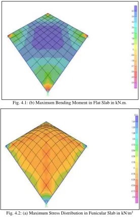
Fig. 4.1: (b) Maximum Bending Moment in Flat Slab in kN.m.
Fig. 4.2: (a) Maximum Stress Distribution in Funicular Slab in kN/m2
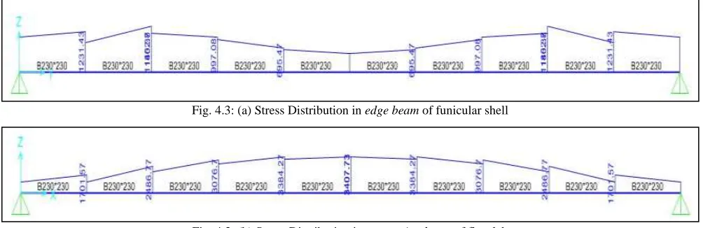
Fig. 4.3: (a) Stress Distribution in edge beam of funicular shell
Fig. 4.3: (b) Stress Distribution in supporting beam of flat slab
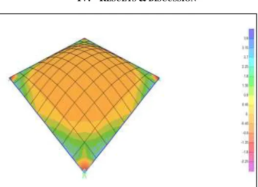
The finite element non-linear parametric analysis of funicular shells compared with the analysis of flat slab in different aspects like stress contours, bending moment diagrams and shear force diagrams as shown above justifies that the funicular shells are more economical and eco-friendly than the flat slabs. The following discussion will give a clear idea about funicular shells. From the figures 4.1 (a) and 4.1 (b) we can see the Maximum Bending Moment Distribution in funicular shell and flat slab
respectively. Maximum portion(central area) in the funicular shell have a bending moment ranging from 0.1 to 1 kN.m where as in the flat slab the bending moment ranges from 1.8 to 6.3 kN.m. This justifies that a funicular shell consumes less material than a flat slab. Therefore funicular shell is lighter than the flat slab.
From the figures 4.2 (a) and 4.2 (b) we can see the MAXIMUM STRESS DISTRIBUTION in funicular shell and flat slab respectively. The moment obtained in figure 4.2(b) is mostly positive which indicate that the slab is subjected to tensile stress. To counter these tensile stresses reinforcement steel should be used, whereas in funicular shell, most of the stresses are compressive in nature therefore reducing steel usage.
From the figures 4.3 (a) and 4.3 (b) we can see the MAXIMUM STRESS DISTRIBUTION in the edge beam and supporting beam respectively. We know that,
M = σ × Z Where, M = Bending moment
σ = Stress
Z = Section modulus
From the above formula, we know that the stress is inversely proportional to the section modulus. If stress is maximum, section modulus is minimum hence the strength of the material also minimum.
From the figures 4.3 (a) and 4.3 (b), we can justify that the section modulus in case of funicular shell is maximum leading to more strength of the material which is more economical compared with the flat slab.
V. CONCLUSIONS
The following conclusions are obtained from the outcomes of the investigation,
The bending moment in the funicular shell is reduced compared with the flat slab which leads to lighter weight of the shell. The stress distribution in the funicular shell is mostly compressive which reduces the steel reinforcement in the shell. The stress distribution in the edge beams of the funicular shell indicates that the section modulus is high leading to the
reduced material cost compared with beams supporting flat slab.
There is decrease in deflections in funicular shell when compared with the flat slab.
In case of uniformly distributed load there is a maximum tension at edges of the shells and compression at the region around the centre of the shell.
REFERENCES
[1] Abolhassan Vafai, Massoud Mofid, “Experimental study of prefabricated funicular shell units”, Engineering Structures, Vol19, No. 9, 1997, Pages 748-759.
[2] Abolhassan Vafai, Massoud Mofid and Homayoon E. Estekanchi, “Experimental study of prefabricated funicular shell units”, Journal of Structural Engineering, Vol 19, No 9, 1997, Pages 748-759.
[3] Albolhassan Vafai and Mehdi Farshad “Theoretical and experimental study of prefabricated funicular shell units”, Building and Environment, 1979, Vol 14, Pages 209 -216.
[4] Bhattacharya and G.S Ramaswamy,”Analysis of funicular shells by the finite element method”, journal of structural Engineering. [5] S.Elangovan and A.R Santhakumar (1988), parametric study on funicular shells.
[6] Reinforced folded plate and shells by P.C Varghese.