ISSN (Online): 2320-9364, ISSN (Print): 2320-9356
www.ijres.org Volume 4 Issue 10 ǁ October. 2016 ǁ PP.01-07
Fem Analysis on the Simulation of the Metal Cutting Process
And It’s Effect in the Research of Deformation Coefficient
Zhang peng-fei, Wang da-zhong, Zhao gang
(College of Mechanical Engineering, Shanghai University of Engineering Science,Shanghai, 201620, China)
Abstract:
Cutting deformation is a process of dynamic change of microstructure of materials, and the calculation of deformation is very complex. This paper uses the finite element software, the metal cutting process was simulated, the deformation results obtained under different conditions of chip analysis, cutting speed, cutting depth and the effect of shear angle of these three variables on deformation coefficient.Keywords:
FEM modeling, deformation coefficient, shear angle, chipI.
INTRODUCTION
Cutting deformation is a process of dynamic change of microstructure of materials, and the calculation of deformation is very complex. This paper uses the finite element software, the metal cutting process was simulated, the deformation results obtained under different conditions of chip analysis, cutting speed, cutting depth and the effect of shear angle of these three variables on deformation coefficient.
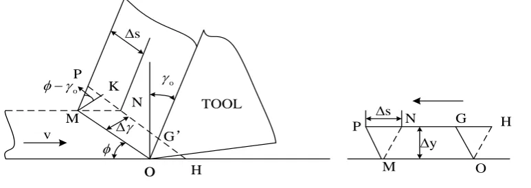
The metal cutting process is actually the process of plastic deformation in the shear slip mainly by cutting metal layer on the rake surface of the cutting tool under the extrusion, figure 2 shows the slip process of the metal. From the figure, the plastic deformation of the metal cutting process can usually be divided into three deformation zone, which is second deformation zone, plastic deformation of metal cutting layer material after the first deformation zone along the rake face out near the rake face is formed. In this deformation area, the material is further intensified due to the extrusion and friction of the cutting layer material, and the material is in the shape of the material, and the flow speed is slowed down, even at the front cutter face. The experiments show that the size of shear angle and cutting force are directly related to the size of the cutting force.
v
o
H M P N KP N G H
O M s y s o G’ o TOOL
Figure 1 Sketch of shear deformation
The same material with the same cutting tool, cutting layer of the same size, when the cutting speed is high, the larger the shear angle, shear area is smaller, at this time, cutting more effort, it can be seen that the shear deformation is an important characteristic of plastic material cutting, shearing angle can be used as a parameter to measure the deformation of the cutting process. Relative slip is the relative slip of the cutting layer on the cutting surface, which is the main form of the metal deformation during the cutting process. The relationship between shear angle and relative slip is derived as follows:
As is shown in the figure 2, the relative slip of the OHNM is changed to OGPM after the shear
deformation occurs in the parallel quadrilateral: s
y
.Visible from the graph, the shear plane NH is
s
NP
NK
KP
y
MK
MK
(1)
0
cot
tan
(2)
0 0
cos
sin cos
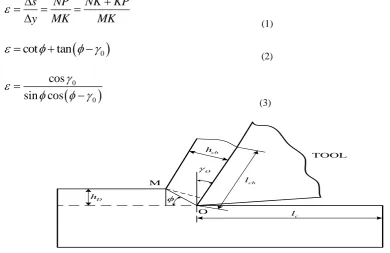
(3) M O TOOL O D h c l ch l ch hFigure 2 Method for calculating deformation coefficient
With the shear angle
to measure the size of the deformation, must be used to quickly cut off the chipto get the root of the chip to get more trouble, generally used to measure the deformation coeffic ient
. As shown in the cutting process, the cutting chip thicknessh
chof the cutting tool is usually greater than thenominal thickness
h
D of the cutting layer on the workpiece, while the chip lengthl
ch is less than the length ofthe cutting layer
l
c. The ratio of the chip thickness to the nominal thickness of the cutting layer is called thethickness deformation coefficient
a, that isA
h, the chip thickness compression ratio, and the ratio of the lengthof the cutting layer to the chip length is called the length deformation coefficient
L: a chD
h
h
, L cch
l
l
.Because the width of the cutting layer on the work-piece is very small, and the average width of the cutting chip
is small, and the volume before and after cutting is unchanged:
a
L
. The deformation
of the chipis directly measured and the deformation of the chip is easily measured. Coefficient of deformation is a factor of more than 1, referred to as the cutting ratio. In the formula,
l
c as is known, the specimen length,l
ch available amount of fine copper wire. The bigger the value, the shorter the chip thickness is, the larger the deformation. Derived from the graph:
0
0
sin 90
cos
sin
sin
ch cOM
h
h
OM
(4) 2 0 02 sin
1
cos
(5)In general, the degree of deformation of the chip is indicated by the shear angle, the relative slip and the deformation coefficient. It should be noted that they are put forward according to the pure shear view, the actual cutting process is complex, both shear and shear face of chip extrusion and friction, so these formulas cannot reflect the essence of the whole deformation.
The cutting deformation coefficient of J Paulo Davim was obtained. The shear plane angle of PMMC (SiC reinforced aluminum alloy) was decreased with the increase of chip deformation coefficient, and the velocity increased slightly. The shear strain rate increases with the increase of speed, and the shear strain decreases slightly increased [1]. Study on the phenomenon and effects of scale factors[2], cutting force and surface roughness prediction[3], the influence of cutting edge radius on cutting process[4 ~ 6] and the research of minimum chip thickness representation and influence factors[7,8] become a hot spot. The prediction model of the
minimum chip thickness is given by using the slip line theory of Liu [7], and the influence of thermal softening
force and feed rate of the relationship between [8]. From this background information, it can be determined that the above mentioned authors have the common view that cutting speed, cutting depth, shear angle have an significantly influences on the chip deformation coefficient. It is useful to study the relationship by finite element method.
II.
D FEM SIMULATION
In order to improve physical comprehension of the chip formation during cutting of ductile metals, a proper fracture criterion is needed. Depending on the FEA simulation platform, a 2D finite element model under plane strain deformation was used to focus on the physical inherence of the influence of the fracture models on cutting performance. The model represents metal cutting experiment. The radial cutting depth is fixed at 4 mm. In the turning configuration, the feed rate (or the axial cu tting depth) is much lower than the radial cutting depth, as it is in the end turning process, where the feed speed (radial direction) is generally much lower than axial depth of cut, therefore plane strain assumption for establish the model is reasonable for this study [9].
Quadrilateral continuum element CPE4RT was used for a coupled temperature -displacement dynamic analysis, in order to acquire the temperature distribution in the cutting process. The material elements’ fracture evolution process can be observed in the FEA analysis by this way, and the effects of different fracture models can be studied. Due to the high computation cost, self-contact was not configured in the model, and only the contact between cutting tool and work-piece was assigned. Neither mass scaling nor additional damping was applied in the simulation [11-13].
The Johnson–Cook model is applied into this research to describe the work-piece material behavior.
This model is capable of modeling large strains, high strain rates, and temperature dependency[10,14]. The cutting
tool material is WC/CO cemented carbide (6%CO) [10,14].
The model is expressed as follows:
0
= 1 ln 1
m
n room
melt room
T T
A B C
T T
(1)
Where σ is the equivalent stress, A is the initial yield stress, B is the hardening modulus, ε is the plastic
strain, C is the strain rate dependency coefficient, is the strain rate, 0 is the reference strain rate, T is the
operating temperature, Troom is room temperature, Tmelt is the melting temperature, and M is the thermal softening coefficient.
III.
RESULTS AND DISCUSSION
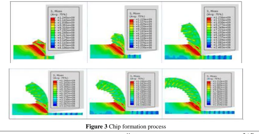
The figure 3 is the metal cutting process and 2D FEM simulation in the state, from the beginning and tool workpiece contact, to eventually produce longer chip, chip is formed, wherein the metal in the process of the shear and slip. When the first saw tooth travel, the shear zone of the first deformation zone is deformed severely, the mesh of the shear zone is stretched and the serious distortion is caused.
Figure 4 Schematic diagram of cutting state
Figure 4 shows cutting state, the lines in the figure represent the average width, and the following lines are the same.
3.1 The study of the effect of cutting depth on deformation coefficient
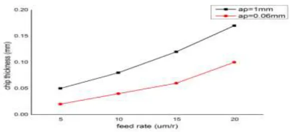
As figure 5 shown is the same speed, different depth conditions, simulation of cutting process, measurements were performed on the L1 and L2 Series in the distance, After measurement, the relationship between the feed rate and cutting depth, as shown in the figure 6, we can see an increase in chip thickness with the feed rate increasing, the macro scale cutting process this trend with the traditional line. It can be seen from the figure the cutting depth is bigger, the greater the chip thickness.
Figure 5 The same speed, different depth conditions
Figure 6 Relationship between feed rate and chip thickness
3.2 Study on influence of cutting speed on deformation coefficient
As figure 7 shown is the same cutting depth, under different speed conditions, simulation of cutting
Figure 7 The same cutting depth, under different speed conditions
Figure 8 Relationship between feed rate and chip thickness
After measurement, the cutting speed and chip thickness can be obtained, as shown in figure 8. It shows that the thickness of the chip will decrease with the increase of the cutting speed, and it also shows that the chip thickness increases with the increase of the feed rate.
3.3 Analysis on the effect of the geometric structure of rake face on deformation coefficient
The measurement shows that the geometric structure of rake face has no influence on the deformation coefficient of chip.
3.4 Study on the influence of the size of the front angle on the deformation coefficient
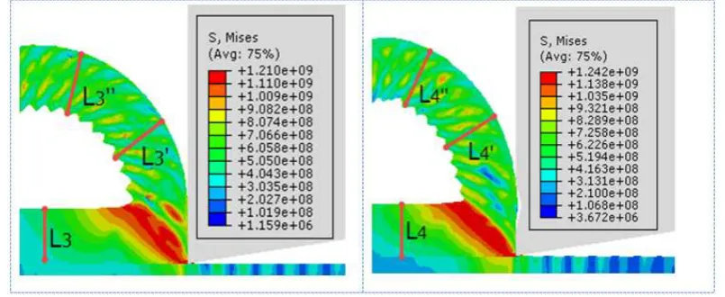
Figure 10 shows that the same at the same depth, the different rake surface angle conditions, simulation of cutting process, measurements were performed on the L4 and L5 Series in the distance,
Figure 10 Different angle of rake face
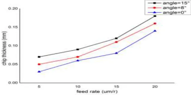
After measurement, we can be obtained between the rake angle and chip thickness, as shown in the figure 11. It shows that with the former angle change, chip thickness will change, and has a direct proportion is higher the rake angle, cutting thickness is greater, while figure also shows that, under this condition, chip thickness increases with the amount of feed increased.
Figure 11 Relationship between feed rate and chip thickness
IV.
CONCLUSION
1. The chip deformation coefficient can accurately reflect the plastic deformation in the cutting process and is
easy to measure. The chip deformation coefficient is the premise of other parameters such as shear angle and cutting force. In order to deeply understand the micro cutting mechanism, it is very necessary to describe the shear deformation coefficient and its variation law in micro machining.
2. With the increase of the feed rate, the width coefficient increases with increase of deformation; cutting depth, width deformation coefficient decreases.
3. The thickness of the chip will decrease with the increase of the cutting speed.
4. The rake face angle change, chip thickness will change, and has a direct proportion is higher the rake angle,
REFERENCES
[1]. Viktor P, Astakhov S. The assessment of plastic deformation inmetal cutting. Journal of
Materials Processing Technology, 2004, 146: 193~202
[2]. Davim J P. Application of merchant theory in machining particulate metal matrix composites. Materials
and Design, 2006, 28:2684~26876
[3]. Subbiah S. Some investigations of scaling effects in micro-cutting. Georgia Institute of Technology, 2006
[4]. M t Zaman A S K. A three-dimensional analytical cutting force model for micro end milling operation.
International Journal of Machine Tools & Manufacture, 2005, 46: 353~ 3668
[5]. Yigit Karpat T O. Design and analysis of variable micro-geometry tooling for machining using 3-D process simulations, Gaithersburg: 2007
[6]. Zeren TO A E. Numerical modelling of meso-scale finish machining with finite edge radius tools. Int. J.
Machining and Machinability of Materials. 2007, 2: 451~46910
[7]. Santosh Ranganath A B. A model to calibrate and predict forces in machining with honed cutting tools
or inserts. Inter-national Journal of Machine Tools & Manufacture. 2007, 47: 820~840
[8]. Wang J. Surface generation analysis in micro end-milling considering the influences of grain. DTIP of
MEMS, 2007: 25~27
[9]. Kawasegi, N, Sugimori H, Morimoto H, Morita Nand Hori I. Development of Cutting Tools With
Microscale and Nanoscale Textures to Improve Friction Behavior, Preci. Eng. 2009, 33(3) : 248-254 [10]. Jian, F. M., Nick, H. D., “Assessment of Micro grooved Cutting Tool in Dry Machining of AISI
1045 Steel,” J. Manu. Science. Eng. 2015, 137: 031001-1
[11]. Dirikolu, M. H., Childs, T. H. C., and Maekawa, K., “Finite Element Simulation of Chip Flow in
Metal Machining,” Int. J. Mech. Sci. 2001, 43(11) :2699–2713
[12]. Jian, L., Yuan, L. B., Cheng, Y. X., “Evaluation of Ductile Fracture Models in Finite Element
Simulation of Metal Cutting Processes,” J. Manuf. Science. Eng., 2014,136 : 011010-1
[13]. P. Z., Shen, F. W., He, P. W., “Predicting the Effects of Cutting Parameters and Tool Geometry on Hard
Turning Process Using Finite Element Method,” ASME. J. Manuf. Eng. 2011, 133 : 041010-1
[14]. Zhang, Y., Mabrouki, T., Nelias, D., and Gong, Y., “FE-model for titanium alloy (Ti–6Al–4V)cutting