Comparative Experimental Study of
R744/R1270Mixture
A.Ramanan
1*, P.Senthilkumar
2, V.Natarajan
3, Amala Justus Selvam
41Research Scholar, Dept. of Mechanical Engineering, Sathyabama University, Chennai-600119, Tamilnadu, India 2Professor, Dept. of Mechanical Engineering, KSR College of Engineering, Tiruchengode-637215, Tamilnadu, India
3Professor, Dept. of Mechanical Engineering, Jeppiar Engineering college, Chennai-600119, Tamilnadu, India 4Professor, Dept. of Mechanical Engineering, Vel Tech University ,Chennai -637215, Tamilnadu, India
*Corresponding author: [email protected] , +91 9443968003
Abstract-- This paper presents the boilingcharacteristics of the refrigerant mixture of R744/R1270 flowing through the horizontal smooth tube of 4mmID and 5mm OD. Experimental results on the heat transfer coefficient, inner wall temperature, exergyand Nusselt number of refrigerant mixture of R744/R1270 are presented. The refrigerant mixture R744/R1270 in combinations of 25/75, 50/50 and 75/25 is studied at different mass flux conditions. It is found that the mixture combination of R744/R1270as75/25 at all mass flux except at a mass flux of 60 kg/ m2 s gives maximum heat transfer.
Index Term-- heat flux, mass flux, refrigerant mixture
I. INTRODUCTION
Conventional refrigerants, such as the CFCs and HFCs, have potential environmental problems, so their use is being restricted. CO2 is non-flammable and nontoxic with a zero ozone depletion potential (ODP), and global warming potential (GWP) is least.; therefore, CO2 is a promising refrigerant for environmental, economical and safety reasons, and is being applied in automobile air-conditioning, heat pump or other low temperature refrigeration systems, as suggested by Lorentzen and Pettersen(1993) and Riffat et al. (1997).
II. EXPERIMENTAL APPARATUS AND PROCEDURE
A. Experimental apparatus
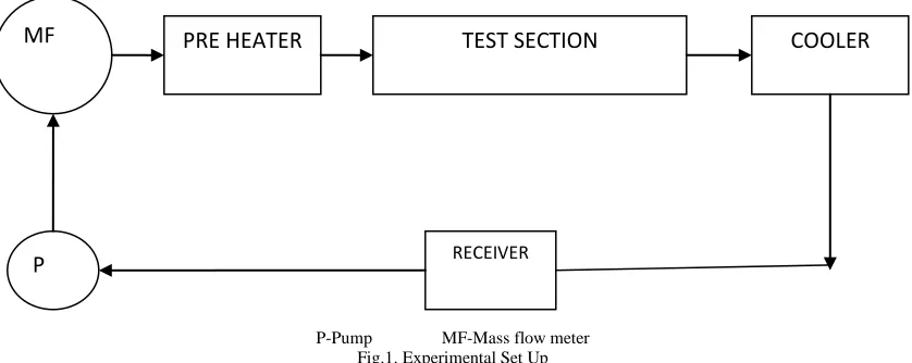
Figure (1) represents the experimental set up used to compare and study the R744/R1270 in a horizontal tube during evaporation and it was used similar to the set up and working as mentioned by Cho et al (1). The refrigerant loop consists of a pump, test section, a Coirolis-type mass flow meter, a pre-heater and a condenser. The liquid refrigerant is pumped via pump. Then the refrigerant passes through a Coirolis-type mass flow meter before entering the pre-heater. The pre-heater is used to control the vapor quality at the test section inlet. The test section consists of 5 mm outer diameter with 0.25 mm thick copper tube having length of 1.44 m. The wall temperature is measured using type-T, thermocouples, positioned on the surface. Pressure is measured at the test section inlet and outlets. Flow boiling tests were then performed for the refrigerant mixture of 25/75, 50/50 and 75/25 proportion at different mass flux conditions.
P-Pump MF-Mass flow meter
MF
P
PRE HEATER
TEST SECTION
COOLER
B. Instrumentation
Instruments used in the experimentation while doing the experiment is listed in the table 1 with their range and accuracy. The instruments where calibrated as per the standard procedure before they were utilised.
Table I
Instruments and its accuracy
Sr.No Instrument Range Accuracy
1 PT100 type
temperature sensors
-50 °C to 100 °C
±0.5
2 Mass Flow Meter 0-400L/ min. ±1.0
3 Pressure gauge 0-500Kg/cm2 ±1.2
The thermo physical properties are calculated based on the measured temperature and pressure. The local heat transfer coefficient at each thermocouple is calculated based on the following equation
dimensional heat conduction equation from the measured outer wall temperature and Tsat is h = q / (Tw -Tsat)
Where, q- heat flux, Tw is the inner wall surface temperature and it is calculated using one the saturated temperature of the refrigerant deduced from the fluid pressure. The variations of the refrigerant thermo-physical properties in the test section were calculated with REFPROP 8.0.
D. Uncertainty analysis
An estimate of the internal uncertainty (Nakra and Chaudhary1991), has been carried out and given in the table 2.
Table II
Percentage of uncertainty of different parameters
Sl. No. Parameter Percentage of uncertainty
R744/R1270 (as75/25 by wt) 1
Test section temperature (°K) ±2.13
2
Test section inlet pressure (bar) ±2.36
3 Test section outlet Pressure(bar) ±5.91
4 Heat transfer coefficient ±3.58
5 Exergy ±2.96
6 Test section inner wall temperature (°K) ±3.39
7 Nusselt number ±4.16
III. RESULTS AND DISCUSSIONS
Heat transfer coefficients (HTCs) are found to depend on some or all of the following parameters: heat flux, reduced pressure, vapor quality and often mass velocity; furthermore they might depend on surface roughness and channel geometry.The variation of heat transfer co efficient, inner wall temperature , exergy and Nusselt number on the quality of refrigerant mixture flowing through the horizontal tube at different mass flux conditions of the refrigerant mixture of R744/R1270 in combinations of 25/75,50/50 and 75/25 is shown in fig. 2-5(a-d).
A. Variation of Heat transfer coefficient on quality of R744/R1270 mixture at different mass flux conditions is shown in fig.2(a-d).
Mass flux-40 kg/ m2 s
0 2 4 6 8 10 12
0 0.2 0.4 0.6 0.8 1 1.2
H
ea
t
tra
ns
fer
co
ef
ficient
Quality
Mass flux-60 kg/ m2 s
Mass flux-70 kg/ m2 s
Mass flux-80 kg/ m2 s
Fig. 2.Variation of heat transfer coefficient vs quality at different mass flux conditions
The heat transfer coefficient of refrigerant mixture in three combination at the mass fluxes of 40, 60,70and 80 kg/
mass flux of 80 kg/ m2 s than the mixture of 50/50 at the same time the highest value is for the mixture combination 0
1 2 3 4 5 6 7 8 9
0 0.2 0.4 0.6 0.8 1 1.2
H
ea
t
tra
ns
fer
co
ef
ficient
Quality
25/75 50/50 75/25
0 2 4 6 8 10 12 14
0 0.2 0.4 0.6 0.8 1 1.2
H
ea
t
tra
ns
fer
co
ef
ficient
Quality
25/75 50/50 75/25
0 2 4 6 8 10 12 14 16
0 0.2 0.4 0.6 0.8 1 1.2
H
ea
t
tra
ns
fer
co
ef
ficient
Quality
follows the similar pattern in the flow. In all the cases the heat transfer coefficient is maximum for the refrigerant mixture of
75/25. different mass flux conditions of 40, 60, 70 and 80 are shown The inner wall temperature along the test section at in the following figure 3(a-d).
Mass flux-40 kg/ m2 s
Mass flux-60 kg/ m2 s 260
265 270 275 280 285 290 295 300 305
0 0.2 0.4 0.6 0.8 1 1.2
Inn
er
w
a
ll
tem
pera
ture
Quality
25/75 50/50 75/25
260 265 270 275 280 285 290 295 300 305 310 315
0 0.2 0.4 0.6 0.8 1 1.2
I
nn
er
w
a
ll
tem
pera
ture
Quality
Mass flux-70 kg/ m2 s
Mass flux-80 kg/ m2 s
Fig.3.Variation of inner wall temperature vs quality at different mass flux conditions
Inner wall temperature of the test section for three refrigerant mixtures namely 25/75, 50/50 and 75/25 is following same pattern for all the mass flux conditions. The inner wall temperature increases along the test section, lower value for 25/75 mixture followed by 50/50 mixture with the maximum value is for 75/25 mixture as evident.
C. Exergy of R744/R1270 mixture at different mass flux conditions
The exergy of the refrigerant mixture flowing through the test section for three combinations at different mass fluxes is shown in the fig.4( a-d).
250 260 270 280 290 300 310
0 0.2 0.4 0.6 0.8 1 1.2
Inn
er
w
a
ll
tem
pera
ture
Quality
25/75 50/50 75/25
265 270 275 280 285 290 295 300 305 310
0 0.2 0.4 0.6 0.8 1 1.2
I
nn
er
w
a
ll
tem
pera
ture
Quality
Mass flux
-60 kg/ m2 s
Mass flux-70 kg/ m2 s
Mass flux-80 kg/ m2 s 0
10 20 30 40 50 60 70
0 0.2 0.4 0.6 0.8 1 1.2
E
x
er
g
y
Quality
25/75 50/50 75/25
0 10 20 30 40 50 60
0 0.2 0.4 0.6 0.8 1 1.2
E
x
er
g
y
Quality
25/75 50/50 75/25
0 10 20 30 40 50 60
0 0.2 0.4 0.6 0.8 1 1.2
E
x
er
g
y
Quality
Fig.4.Variation of exergyvs quality at different mass flux conditions
Exergy variation of mixtures in all the three combinations at four different mass fluxes 4, 60, 70 and 80 are following the same pattern in general. The exergy of fluid decreases towards the end of tube. The exergy value of 25/75 mixture refrigerant lies in between the higher value of 50/50 and lower value of 75/25 mixtures. The exergy of the mixture approaches close value at end point of the tube for the mass fluxes 40,60and 70 kg/ m2 s and for 25/75 and 50/50 combinations.
D. Nusselt number of R744/R1270 mixture at different mass flux conditions
The Nusselt number of the refrigerant mixture flowing through the test section for three combinations at different mass fluxes is shown in the fig.5( a-d).
Mass flux-40 kg/ m2 s
Mass flux-60 kg/ m2 s 0
10 20 30 40 50 60 70
0 0.2 0.4 0.6 0.8 1 1.2
E
x
er
g
y
Quality
25/75 50/50 75/25
0 2 4 6 8 10 12 14
0 0.2 0.4 0.6 0.8 1 1.2
N
u
Quality
25/75 50/50 75/25
0 2 4 6 8 10
Nu
Mass flux-80 kg/ m2 s
Fig.5.Variation of Nusselt number vs quality at different mass flux conditions
Nusselt number variation of mixtures in all the three combinations at four different mass fluxes 4, 60, 70 and 80 are following the same pattern in general. The Nusselt number of fluid decreases towards the end of tube. The Nusselt number value of 25/75 mixture refrigerant lies in between the higher value of 50/50 and lower value of 75/25 mixtures. The Nusselt number of the mixture approaches close value at end point of the tube for the mass fluxes 40,60and 70 kg/ m2 s and for 25/75 and 50/50 combinations.
IV. CONCLUSIONS
Experimental results for the flow boiling of R744/R1270 as 25/75, 50/50 and 75/25mixture combination in a horizontal tube under variations in the mass flux, heat flux and inlet temperature were presented. The behaviours of the local heat transfer coefficient,inner wall temperature and exergy of different blends were investigated and the following conclusions could be drawn from this study.
The heat transfer coefficient initially high and starts decreases towards the end of the in all cases experiment in general. The blend variation influences the heat transfer
coefficient as it is clearly evident from the plots.In the low heat flux conditions, it was possible to observe a significant influence of heat flux on the heat transfer coefficient. In the high heat flux conditions, this influence tends to disappear.
The inner wall temperature increases in all conditions for all blends towards end of the tube at the same time variations in blend influences and similarly the exergy decreases from the beginning to towards end of tube with the influence of blend. Nusselt number variation of mixtures in all the three combinations at four different mass fluxes 40, 60, 70 and 80 are following the same pattern in general.
This research work has been carried out to find an environment friendly refrigerant mixture under fixed working conditions which was not desirable one.
To fully exploit the opportunity with natural refrigerants, it is necessary to rely on acceptable general predicting procedures are still far from satisfactory, and an increased research effort on this matter definitely desirable. Therefore further research may be carried out with higher range of mass fluxes, for varied mixture combination and also for real working conditions instead of fixed conditions. So that 0
1 2 3 4 5 6 7 8 9
0 0.2 0.4 0.6 0.8 1 1.2
N
u
Quality
25/75 50/50 75/25
0 2 4 6 8 10 12
0 0.2 0.4 0.6 0.8 1 1.2
N
u
Quality
the application range may be expanded for the refrigerant mixture.
REFERENCES
[1] Jin Min Cho,Yong Jin Kim and Min Soo Kim (2010) Experimental studies on the characteristics of evaporative heat transfer and pressure drop of CO2 /PROPANE mixtures in horizontal and vertical smooth and microfin tubes,IJR,33,170-179.
[2] Jin Min Cho, Yong Jin Kim and Min Soo Kim(2010) Experimental studies on the evaporative heat transfer and pressure drop of CO2 and CO2 /propane mixtures flowing upward in smooth and micro-fin tubes with outer diameter of 5mm for an inclination angle 45 0,IJR,33,922-931.
[3] Jin Min Cho and Min Soo Kim (2007) Experimental studies on the evaporative heat transfer and pressure drop of CO2 smooth and microfin tubes of diameters 5 and 9.52 mm,IJR,30,986-994. [4] Cooper, M.G., 1989. Flow boiling-the apparently nucleate regime.
Int. J. Heat Mass Transfer 32, 459-464.
[5] C.Y. Park, P.S. Hrnjak (2007)CO2 and R410A flow boiling heat transfer, pressure drop, and flow pattern at low temperatures in a horizontal smooth tube, International Journal of Refrigeration 30 ,166-178,
[6] Mao-Yu Wen a,*, Ching-Yen Ho(2005)Evaporation heat transfer and pressure drop characteristics of R-290 (propane), R-600 (butane), and a mixture of R-290/R-600 in the three-lines serpentine small-tube bank, Applied Thermal Engineering 25 (2005) 2921–2936
[7] Xiaoyan Zhang , ChangfaJi , Xiuling Yuan (2008)Prediction method for evaporation heat transfer of non-azeotropic refrigerant mixtures flowing inside internally grooved tubes ,Applied Thermal Engineering 28 (2008) 1974–1983