Cfd Analysis On Performance And Emissions In Di
Diesel Engine With High Pressure Injections
K.Bala Showry
Principal, DRKInstitute of Science and Technology, Hyderabad, India. Email: [email protected]
ABSTRACT: An emissions and performance study was performed to show the effects of injection pressure, nozzle hole inlet condition (sharp and rounded edge) and nozzle included spray angle on particulate, NOX, and BSFC. The Simulations were conducted on a fully instrumented single-cylinder version of
the Caterpillar 3406 heavy duty engine at 75% and 25% load at 1600 RPM. Commercial validation tool FLUENT was used for numerical simulation. This tool solves the basic governing equations of fluid flow that is continuity, momentum, species transport and energy equation. Using finite volume method Turbulence was modeled by using standard k-έ model. Injection was modeled using LaGrangian approach. The reaction was modeled using non – premixed combustion which considers the effects of turbulence and detailed chemical mechanism into account to model the reaction rates. The specific heats for all the species was approximated by using piecewise polynomials. The fuel system consisted of an electronically controlled, common rail injection system with an injection pressure of 160 M Pa. Particulate versus NOX trade-off curves were generated for each case by varying the injection
timing. The 75% load results showed the expected decrease in particulate and flattening of the trade-off curve with increased injection pressure. However, in going from 90 to 160 M Pa, the timing had to be retarded to maintain the same NOX level, and this resulted in a 1 to 2% increase in BSFC. The rounded
edged nozzles were found to have an increased discharge coefficient. By adjusting the injection pressure, it was possible to compare the performance of the rounded and sharp edged nozzles with the same mass rate of injection profiles. Interestingly, the sharp edged nozzle gave significantly lower particulate emissions and lower BSFC at lower injection pressures. However, as the injection pressure was increased the difference in particulate became smaller and the rounded edged nozzles gave lower BSFC. Two nozzle spray angles with included angles of 125 and 140 degrees were studied. The effects of spray angle on particulate and NOX emissions were found to be small at high load, but differences were seen at light load. These results are
interesting because the spray in the 125 degree case is directed so as to give significant spray impingement on the piston bowl wall, while the 140 degree nozzle has minimal wall impingement.
Keywords: NOX, particulate matter ,computational fluid dynamics .start of injection, duration of injections
1I
NTRODUCTIONThe Diesel Engine is widely used in heavy duty transport ap-plications. Although more fuel efficient than their spark ignited counterpart, they have relatively higher emissions and noise levels. Diesel engine manufacturers have to address these problems to meet current and future government regulations, which limit particulate and NOX emissions, while maintaining a quiet efficient engine to satisfy consumers. Particulate and NOX production along with engine noise is highly dependent on combustion process. Therefore precise control over the fuel injection and spray formation is essential in making improve-ments to the combustion process. Current trends to increase injection pressure and decrease nozzle hole diameter to re-duce particulate emissions can be attributed to better atomiza-tion and fuel-air mixing. Unfortunately, this usually results in higher NOX production which is believed to be due to locally higher temperatures and oxygen rich regions near the begin-ning of the combustion process [1]. The rate of NOX formation can be slowed by retarding timing to reduce peak cylinder tem-peratures and pressures. This, however, is not as efficient and increases fuel consumption. In order to address the particulate- NOX trade-off without sacrificing fuel consumption, it is impor-tant to understand the relationships between various injection parameters and how they affect the combustion process. Along with injection pressure and nozzle hole diameter, other injection parameters such as nozzle hole L/D ratio, nozzle inlet R/D ra-tio, and rate of injection profile effect the fuel spray. Spray cha-racteristics that may be affected are droplet size, spray pene-tration, exit velocity, and spray cone angle. The details of the rate-of-injection profile significantly influence engine emissions. For example, Tow et al. [2] have shown that the use of multiple injections can reduce particulate emissions by as much as a factor of three without increasing NOX emissions. This was at-tributed to better mixing later in the cycle. However, the present study was limited to a single injection, and concentrates on the
fuel consumption (BSFC) in a D.I. heavy duty diesel engine. The fuel system used has electronically controlled injection timing and duration. Fuel injection pressure was variable up to 160 M Pa. Four nozzle configurations combining rounded and sharp-edged nozzles with included spray angles of 125° and 140° were used. The process to attain the rounded-edged zles is one in which an abrasive fluid is forced through the noz-zle holes. This fluid wears the material in any location where the flow is restricted, resulting in rounded edges on the fuel side and an increased discharge coefficient of the nozzle [7]. Particulate vs.NOX trade-off curves were generated for the various injection pressures and nozzle configurations. Heat release analysis of the cylinder pressure provided further in-sight into the combustion process.
2SIMULATION
Model formulation
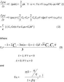
The computer code used in this study was FLUENT. The code can solve unsteady, compressible turbulent flows with com-bustion and fuel spray, and have been used for the computa-tions of various internal combustion engines The code uses a finite volume methodology to solve discretized Navier-strokes equations. RNGK-έ was used in this study. It could predict more realistic large scale flame structures compared with the K-έ model. The RNG K-έ model is formulated as
t
+· (ρuk) =
3
2
ρk · u +u +·kkρ+W s
(1)
t
+·ρu=-[
3
2
C1–C3+
3
2
CC·u]ρ·u+·
+
[ ( C1-Cn)u-C2ρ+CsW s
] ( 2)
Where
C3=
C
C
C
3
m
(
n
1
)
(
1
)
6
2
1
13
(3) = 1; if ·u < 0
= 0; if ·u > 0
and
C = 3 0
1
1
(
)
In equation (1)-(3) k and are turbulent kinetic energy and its dissipation rate .ρ,u, and are density, velocity, stress tensor and effective viscosity respectively. is the ratio of the turbu-lent –to mean –strain time scale . S is the magnitude of the
mean strain. m =0.5, and n =1.4.The C3 term accounts for the non- zero velocity dilatation which is closed.
3Mathematical models
Spray model
Modeling of fuel injection is an important and essential part of direct injection diesel engine simulation. Fluent uses fully coupled stochastic Lagrangian-Eulerian approach to avoid the necessity to empharically tune coefficients or other inputs of the spray model. The break up model proposed by Reitz and Diwakar is used to simulate the droplet break up process.
Atomization model
Among various atomization models which are inbuilt in fluent, pressure swirl atomizer with swirl dominated flow has been chosen for this study.
Spray impingement model
Spray impingement model proposed by A.D.Gosman and Bai is used as it is formulated in concern with Lagrangian ap-proach, here mass momentum and energy conservation are constraints. I n the present study, high pressure fuel injection with solid cone spray is simulated in DI Diesel engine [16].
Nozzle flow model
The injection velocity of the liquid fuel as it exits the nozzle and enters the combustion chamber, is the most important parame-ter in spray calculations. It strongly influences the atomization and break-up process, penetration, the inner phase transfer process, and droplet to droplet interaction. The main feature of this model is the recognition of a separation, cavitation region initiating from the entrance of the nozzle entrance. Depending upon the pressure in the chamber relative to the critical pres-sure at which cavitation commences, and the length of the cavitation region, the model distinguishes three different flow regimes, i.e. the non cavitating flow, the cavitating flow inside the nozzle, and the cavitating flow at the exit of the nozzle.
Turbulent dispersion of particles
Dispersion of particles due to turbulent fluctuations in the flow can be modeled using either Stochastic tracking (discrete random walk) Particle cloud model. Turbulent dispersion is important because it is more realistic, enhances stability by smoothing source terms and eliminating local spikes in coupl-ing to the gas phase.
Table 1. Engine Specifications
Engine Type
Caterpillar 3406 - single cylind-er - direct in-jection - 4 valve
Bore x Stroke 137.2 mm × 165.1 mm
Compression Ratio 15.1 : 1
Displacement 2.44 liters
Combustion Chamber Quiescent
Piston Mexican Hat
Table 2. Fuel System Specifications
Injector type ElectronicallyControlled Unit Injector
Injection Pressure Variable (up to 160 M Pa)
Number of Nozzle Holes 6
Nozzle Hole Diameter .259 mm
Nozzle Hole Inlet Condition Rounded and Sharp Edged
Spray Angle (included) 125 and 140 degrees
Two engine conditions (75% and 25% of Peak Torque at 1600 RPM) were chosen to simulate important operating conditions taken from the operating map of a six cylinder pro-duction version of the engine. Engine conditions at these loads are shown in Table 3.
4 RESULTS AND DISCUSSION - 75% LOAD
The results of the 75% load cases are presented first. These include a study of the effects of injection pressure, nozzle inlet condition, and nozzle included spray angle on emissions and performance. The results of the 25% load cases follow next.Figure 1 Fuel injection pressure and injection profile
NOMENCLATURE - The following convention will be used to describe the injection pressure and nozzle configuration used for each test.
160-125(S)
Where: 160 = Peak Injection Pressure (M Pa) 125 = Nozzle Included Spray Angle (°) (S) = Sharp edged Nozzle
(R) = Rounded edged Nozzle
Table3. Test Conditions (nominal)
Load 75% 25%
Speed 1600 RPM 1600 RPM
Power 37 kW 12 kW
Torque 220 N-m 75 N-m
Equivalence Ratio 0.55 0.31 Intake
Temperature
36 C 28 C
Intake Pressure 183 k Pa 117 k Pa
Exhaust Pressure 159 k Pa 117 k Pa
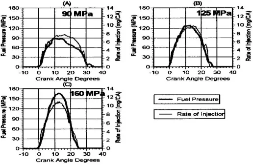
EFFECTS OF INJECTION PRESSURE - The fuel injection pressure along with the corresponding Bosch rate-of-injection
as a function of crank angle is shown in Fig.1 for the instru-mented injector with the 140° sharp-edged nozzle (140(S)). The rate of injection correlates well with injection pressure as
it should. For the three cases shown in Fig.1 the mean injec-tion pressure is significantly less than the peak pressure. The
mean injection pressures for are 58, 81, and 99 M Pa while the peak injection pressures are 90, 125, and 160 M Pa re-spectively. Therefore the mean injection pressure averages 60%-65% of the peak pressure for the cases studied. The fuel
pressure data was only available for the instrumented injector described above. For the other injectors, the peak pressure is
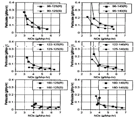
known to be about 7 times the high pressure oil pressure. Particulate vs. NOX trade-off curves are presented in Fig.2 for
the four nozzles tested. The trade-off curves typically consist of five data points taken 3 CA degrees apart over a range of 12 CA degrees (nominally +3° to -9° ATDC). Each nozzle shows the characteristic decrease in particulate and flattening
of the trade-off curve with an increase in injection pressure. However, there does seem to be a point of diminishing
re-turns as injection pressure is increased. For example in Fig.2b, there is large decrease in particulate in going from 72 to 96 M Pa, and a substantial improvement from 96 to 122 M Pa, but the gains are rather small between 122 and 160 M Pa. Since the driving torque required by the fuel system
in-creases with increased injection pressure there may be a point where increasing the fuel pressure to decrease particu-late is not worth the sacrifice in BSFC. Also, when raising the
injection pressure from 90 to 160 M Pa the timing must be retarded in order to maintain the same NOX level. This is due
to the higher rate of injection and higher premix burn fraction which contribute to an increase in NOX . These timing retards
will increase in BSFC by 2%. Figure 3 shows particulate and brake specific fuel consumption (BSFC) at a constant level of
NOX (4g/ bhp-hr) for each nozzle and injection pressure tested. (If a data point did not correspond to 4 g/bhp hr of NOX exactly then values were interpolated between two data points.) With injection pressures increasing from right to left it is clear that the general trend is decreased particulate
Figure 2 Effects of injection pressure on the particulate vs.
NOX tradeoff curve for various nozzle configurations tends to increase about 3% in going from 72 to 160 M Pa while holding NOX constant. This increase is due entirely to timing retard to maintain low NOX since the fuel system was driven externally. If effects of fuel system power requirements were included, which were not measured in this study, the increase in BSFC in going from 72 to 160 M Pa would be even more substantial. An estimate of this, calculated according to Shimada [3], is an additional 1% increase in BSFC for the 72 M Pa case and a 2.3% increase for the 160 M Pa case.
Figure 3 Particulate and brake specific fuel consumption (BSFC) at constant NOx (4g/bhp-hr) for the different injection
pressures and nozzle configurations tested
The cylinder pressure, apparent heat release rate, and rate of injection for the 125° rounded-edged nozzle (125(R)) at vari-ous injection pressures is shown in Fig. 4. The injection tim-ings for these four points correspond as closely as possible to cases with 4g/bhp-hr of NOX. It is seen that the rate-of-injection and premixed burn fraction increases while rate-of-injection duration and combustion duration decreases as injection pressure increases. Also notice the large difference in injec-tion timing required to maintain similar NOX levels between the 72 and 160 M Pa cases.Another interesting phenomenon encountered in Fig.3b and 3d is the reversal of the NOX trend at high injection pressures and retarded timings. For both 160 M Pa (R) cases as timing was retarded to about 5° ATDC the NOX level increased. The heat release plots for these two cases are shown in Fig.5. For all cases studied the ignition delay was 4° or 5° when the start of injection was before TDC. However, when the start of injection took place after TDC, ignition delay ranged from 5° to 7°. For the two extreme cases shown in Fig.6 the ignition delays are 7°. This relatively long delay along with the high rate-of-injection due to the (R) nozzles result in large premixed burn fractions and thus high-er NOx.
Figure.4 Cylinder Pressure (top), Apparent Heat Release Rate (middle), and Rate-of-injection (bottom) for the 125(R) nozzle at
conditions resulting in 4g/bhp-hr of NOx
Figure 5Cylinder Pressure (top), Apparent Heat Release
Rate(middle),and Rate-of-injection (bottom) for (R)nozzles at retarded timing and 160 M Pa peak injection pressure. EF-FECTS OF NOZZLE INLET CONDITION - In comparing the rounded-edged (R) nozzles to the sharp-edged (S) nozzles it was thought to be important to maintain the same rate of injec-tion in
Figure 6Rate-of-injection profiles for the (R) and (S) nozzles at different injection pressures
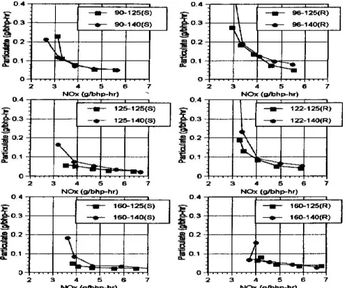
Figure 7 Particulate vs. NOx tradeoff curves comparing the (R) and (S) nozzles with the same rate-of-injection
The nozzle discharge coefficients for the sharp and rounded edged nozzles were estimated to be 0.64 and 0.72 respective-ly. The injection pressure of the 90 M Pa (S) case was lowered to 72 M Pa for the (R) case which resulted in approximately the same rate-of-injection profile for each. The rate-of-injection profiles for each case are shown in Fig.6. As shown in Fig.6 the 90 M Pa (S) case corresponds to the 72 M Pa (R) case, the 125 M Pa (S) case to the 96 M Pa (R) case, and the 160 M Pa (S) case to the 122 M Pa (R) case. The reason the rate-of-injection was thought to be important is because computer modeling uses the rate of injection and exit velocities as pa-rameters, not the injection pressure itself. Therefore, assum-ing that the liquid jet diameters are the same, the models would not know the difference between the (R) and (S) cases with the same rate of injection profile as shown in Fig.7 (e.g., Patterson et al. [15]. Figure 7 shows the Particulate vs. NOX trade-off curves for these cases. Even though the hole size, spray angle, injection duration, and mass rate of injection are all the same for these comparisons, there is a large difference in particulate emissions. The (S) cases result in much lower particulate for all injection pressures tested. The dramatic dif-ference in particulate needs explanation. One possibility is that the nozzle L/D ratio (~2.9) is small enough such that the flow of the sharp edge nozzle separates at the inlet and does not reat-tach before exiting the nozzle. If this were the case the mean exit velocities of the comparisons in Figs.7 and 8 would not be the same. However, if the flow of the sharp edged inlet nozzle does reattach to the wall, and the mean injection velocities are the same, Karasawa et al.[5] and Su and Farrell [6] showed that indeed sharpedged-inlet nozzles produced smaller drop-lets than rounded-inlet nozzles for the same mean injection velocity. This result would explain some of the difference in particulate seen in Fig.8. Further, Karasawa argued that if the actual injection velocity is corrected with the nozzle discharge coefficient, such that
Vcorrected = Vactual / Cd
then the dependence of droplet size on the nozzle configura-tion is eliminated, and droplet size depends on the corrected mean injection velocity only. To test whether this concept can also be applied to engine emissions, Fig. 9 shows particulate
(at NOx = 4g/bhp-hr) vs. corrected mean injection velocity for the (R) and (S) nozzles. Apparently particulate emissions do not correlate as well with nozzle discharge coefficient as the droplet size does or the data would collapse to one line. In-stead the (S) nozzles are less sensitive to corrected mean injection velocity than the (R) nozzles. Therefore, at this NOx level, the (S) nozzles can use lower injection pressures than the (R) nozzles and still have low particulate. Again, the data in Fig 8 assumes the flow in the sharp-edged nozzle reat-taches to the nozzle wall before the nozzle exit.Figure 9 shows particulate vs. NOx trade-off curves comparing the (R) and (S) nozzles with similar injection pressures instead of similar rates of injection. Note that (R) nozzles have a shorter injection duration than the (S) nozzles due to their higher dis-charge coefficients. Again, the (S) nozzles have lower particu-late emissions for all injection pressures studied. Even for the cases in Fig. 9 where the (R) case has a slightly higher peak injection pressure than the (S) case, the (S) nozzle produces less particulate. This may be attributed to better atomization and other spray characteristics. However, the fuel-air mixing may also change due to the difference in injection duration which may contribute to differences in emissions.
Figure8Particulate (at 4g/bhp-hr) of Nox vs. correctedmean injection velocity for the different nozzles tested
In terms of the combustion characteristics, the (S) nozzles had an average of 0.8 CA degree shorter ignition delay and a 4 CA degree shorter combustion duration than the (R) cases with the same rate of injection.
This implies that the (S) nozzles provide a more favorable fuel-air mixture for burning throughout the combustion process. In this case the combustion duration is taken from the start of combustion to 95% burn point according to the heat release program [12].
Figure 10 Particulate vs. NOx tradeoff curves comparing the 125° and 140° nozzles.
THE EFFECTS OF SPRAY ANGLE - Nozzles with included spray angles of 125° and 140° were tested to study the ef-fects of spray impingement on them piston bowl wall. The 140° spray angle is parallel to the piston bowl so minimal wall impingement should occur, while computations [15] show the 125° spray angle to have significant wall impinge-ment. Interestingly, the effects of spray angle on the particu-late vs. NOX trade-off curves were found to be small. Figure 10 shows these results for the (R) and (S) nozzles at various injection pressures. In most cases the difference is quite small. The exceptions are at high injection pressures where the 125° nozzle shows a slight improvement over the 140° nozzle for the (S) nozzles. Although there were no significant differences in the emission levels between the 125° and 140° nozzles, there was some unexpected behavior for the 140° nozzles as injection pressure was increased which was not seen with the 125° nozzle. Referring back to Fig.3, note the strange trend that the tradeoff curves of the 140° nozzle dis-plays. The trade-off curves with different injection pressures all cross around the 4 g/bhp-hr NOX level. Below this NOX level the lower injection pressures actually have lower particu-late emissions. This was not seen with the 125° nozzle. A possible explanation follows. The ignition delay and combus-tion duracombus-tion for the 140° nozzles averaged .4 and 5 CA de-grees longer than the 125° nozzles, respectively. With the retarded timings (past TDC) to control NOx, the longer igni-tion delays, and the combusigni-tion extending later in the cycle, the higher pressure injections of the 140° nozzles are not able to control particulate as effectively as the 125° spray angle cases. Also, these differences in the combustion cha-racteristics translate into a 1-1.5% increase in BSFC for the 140° nozzles compared to the 125° nozzles.
Fig11 injeection profile 125˚
Fig 12 25% load
EFFECTS OF INJECTION PRESSURE - Due to the short in-jection duration at 25% load there is not enough time available for the fuel injection pressure to reach its peak theoretical val-ue of 7 times the high pressure oil pressure. Therefore a com-prehensive study of the effects of injection pressure using all four nozzle configurations was not attempted. Only the sharp edged nozzles were tested at several different injection pres-sures.Figure 11 shows the Bosch rate-of-injection for the 125(S) nozzle. Based on data taken with the instrumented injector, the peak injection pressure for
Figure 13 Apparent rate of heat release for the 125(S) nozzle at the same timing and different injection pressures
This is because the difference in mean injection pressure is small. However, there is a significant difference in the NOx levels between cases with the same start of injection timing. The most significant differences between the three injections is the initial rate of rise of the injection. This implies that rate shaping is very important in controlling the premix burn at 25% load. The effects of the different rate shaped injections on the heat release are shown in Fig. 13. Note that the slower rate of rise results in lower premix burn peak. Ideally, the rate of rise should be slow enough that only a portion of the fuel is in-jected prior to ignition. This would help reduce the premix burn and hence reduce NOx emissions, as also noted by Tow et al. [2] who used multiple injections to reduce the premix burn. EFFECTS OF NOZZLE INLET CONDITION Only one injec-tion pressure was used to test the (R) nozzles at 25% load. This pressure corresponds to the 78 MPa case for the (S) nozzles. The (R) nozzle results in an increased rate of rise of the rate-ofinjection profile compared to the (S) case. The 78 MPa (R) case has a similar rate-of-injection profile to the 106 MPa (S) case as shown in Fig. 13. This increase in the rate of rise, due to the higher discharge coefficient of the (R) nozzle, has the same effect as raising the injection pressure with the (S) nozzles. It is seen that there is still no significant differ-ence in particulate and the NOx levels are the same, as they should be since they have the same rate-of-injection profiles.
CONCLUSIONS
The following conclusions can be drawn from the present ex-perimental results.
75% LOAD –
1. Raising the injection pressure effectively reduces parti-culate emissions. However, to maintain the same NOx level, timing must be retarded resulting in an increase in BSFC. Also, the benefits of particulate reduction as in-jection pressure is raised above 90 MPa are smaller such that the particulate reduction may not outweigh the sacrifice in BSFC.
2. Rounded-edged nozzles have higher discharge coeffi-cients than sharp-edged nozzles. Therefore, rounded-edged nozzles require a lower injection pressure to get the same rate-of-injection as a sharp-edged nozzle. However, particulate emissions for a rounded-edged nozzle are much higher compared to a sharp-edged noz-zle with the same rate-of-injection. Comparing rounded and sharp-edged nozzles with similar injection pressures, again the sharp-edged nozzles produce less particulate emissions.
3. Spray angles with significant piston bowl wall impinge-ment compared to minimal wall impingeimpinge-ment show little difference in emissions. However, ignition delay and combustion duration are shorter with wall impingement resulting in improved BSFC.
25% LOAD –
1. Rate shaping is important to control the premix burn mode of burning and hence NOx production. A slow rate of rise of the rate-of-injection profile is preferred to re-duce the amount of fuel injected prior to ignition.
2. Rounded-edged nozzles increase the rate of rise of the rate-of-injection profile, similar to raising the injection pressure, resulting in increased NOx emissions.
3. Fuel effects are more significant at light loads since the
combustion is predominantly in the premixed mode of burning where chemistry effects are important.
R
EFERENCES[1] S.L. Plee, T. Ahmad, and J.P. Myers, "Flame Tem-perature Correlation for the Effects of Exhaust Gas Recirculation on Diesel Particulate and NOx Emis-sions", SAE Paper 811195, 1981.
[2] T.C. Tow, D.A. Pierpont, and R.D. Reitz, "Reducing Particulate and NOx Emissions by Using Multiple In-jections in a Heavy Duty D.I. Diesel Engine", SAE Pa-per 940897, 1994.
[3] T. Shimada, T Shoji, and Y Takeda, "The Effect of Fuel Injection Pressure on Diesel Engine Perfor-mance", SAE Paper 891919, 1989.
[4] S. Shundoh, T. Kakegawa, and K. Tsujimurwa, "The Effect of Injection Parameters and Swirl on Diesel Combustion with High Pressure Fuel Injection", SAE Paper 910489, 1991.
[5] T. Karasawa, M. Tanaka, K. Abe, S. Shiga, and T. Kurabayashi, "Effect of Nozzle Configurations on the Atomization of Steady Spray", ICLASS-91, July 1991.
[6] J. Su and P.V. Farrell, "Nozzle Effects on High Pres-sure Diesel Injection", SAE Paper 950083, 1995.
[7] T.R. Ohrn, D.W. Senser, and A.H. Lefebvre, "Geome-trical Effects on Discharge Coefficients for Plain-Orifice Atomizers", Atomization and Sprays, Vol. 1, no. 2, pp. 137-153, 1991.
[8] S.f. Glassey, A.R. Stockner, and M.A. Flinn, "HEUI - A New Direction for Diesel Engine Fuel Systems", SAE Paper 930270, 1993.
[9] A.R. Stockner, M.A. Flinn, F.A. Camplin, "Develop-ment of the HEUI Fuel System - Integration of Design, Simulation, Test, and Manufacturing", SAE Paper 930271, 1993.
[10]"Measurement of Carbon Dioxide, Carbon Monoxide, and Oxides of Nitrogen in DieselExhaust", SAE J177, 1982.
[11]D.A. Nehmer and R.D. Reitz, "Measurement of the Ef-fect of Injection Rate and Split Injections on Diesel Engine Soot and NOx Emissions", SAE Paper 940668, 1994.
[12]R.B. Krieger and G.L. Borman, "The Computation of Apparent Heat Release for Internal Combustion En-gines", ASME 99-WA/DGP-4, 1966.
[13]D.R. Tree, "A Study on the Effects of Aromatics on Exhaust Particulates and Soot in a Direct Injection Di-esel Engine", Ph.D. Thesis, University of Wisconsin-madison, 1992.
Instantaneous Heat Transfer Coefficient in the Internal Combustion Engine", SAE Paper 670937, 1967.
[15]M.A. Patterson, S.-C. Kong, G.J. Hampson, and R.D. Reitz, "Modeling the Effects of Fuel Injection Charac-teristics on Diesel Engine Soot and NOx Emissions", SAE Paper 940523, 1994.