Implementation of a Fast Adder Using QSD
for Signed and Unsigned Numbers
C.V.Sathish Kumar(1),P.Jaya Rami Reddy (2)
M.tech Scholar, DECS, Dr.K.V.Subbareddy Institute of Technology (1)
ASST.Professor, Dr.K.V.Subbareddy Institute of Technology (2)
Abstract: In this paper, we proposed an
incipient number system for ALU. In binary number system carry is a major quandary in arithmetical operation. We have to suffer O(n) carry propagation delay in n-bit binary operation. To overcome this quandary signed digit is required for carry free arithmetical operation. Carry look ahead avails to amend the propagation delay to O(log n), but is bounded to a minute number of digits due to the intricacy of the circuit. A carry-free arithmetic operation can be achieved utilizing a higher radix number system such as Quaternary Signed Digit (QSD). In QSD, each digit can be represented by a number from -3 to 3. This number system sanctions multiple representations of any integer. By exploiting this feature, we can design an adder without ripple carry. Quaternary Signed Digit (QSD) have a major contribution in higher radix (=4) carry free arithmetical operation. For digital implementation, the signed digit quaternary numbers are represented utilizing 3-bit 2‟s compliment notation. In this paper, a simple and incipient technique of binary (2‟s compliment) to QSD conversion is proposed and described.
.
Keywords: quaternary sign digit(QSD),
expeditious computation, multiplier, quaternary logic,ALU.
I. Introduction
The sundry digital systems such as computers and signal processors, arithmetic operation plays paramount role. The speed of system increases with incrementing the speed of additament and multiplication. In conventional binary number system, carry may propagate all the way from the least consequential digit to the most paramount. Thus the integration time is dependent on the word length.
Arithmetic operations are widely used and play consequential roles in sundry digital systems such as computers and signal
processors. QSD number representation has magnetized the interest of many researchers. Additionally, recent advances in technologies for integrated circuits magnify scale arithmetic circuits felicitous for VLSI implementation [1][2]. However, arithmetic operations still suffer from kenned quandaries including constrained number of bits propagation time delay, and circuit intricacy.
In this paper, we propose a high speed QSD arithmetic logic unit which is capable of carry free integration, borrow free subtraction, up-down count and multiply operations. The QSD integration/subtraction operation employs a fine-tuned number of minterms for any operand size. The multiplier is composed of partial product engenderers and adders. For accomodation of testing and to verify results, we opt to implement the units utilizing a programmable logic contrivance.
II. Technique Of Conversion From Binary Number To QSD Number
1-digit QSD can be represented by one 3-bit binary equipollent as follows:
So to convert n-bit binary data to its equipollent q-digit QSD data, we have to convert this n-bit binary data into 3q-bit binary data. To achieve the target, we have to split the 3rd, 5th, 7th bit…. i.e. aberrant bit (from the
LSB to MSB) into two portions. But we cannot split the MSB. If the aberrant bit is 1 then, it is split into 1 & 0 and if it is 0 then, it is split into 0 & 0. An example makes it clear, the splitting technique of a binary number (1101101)2is shown below:
So we have to split the binary data ( 1) q− times (as example, for conversion of 2-bit quaternary number, the splitting is 1 time; for converting 3-digit quaternary number the split is 2-times and so on). In each such splitting one extra bit is engendered. So, the required binary bits for conversion to its QSD equipollent (n) = (Total numbers of bits engendered after divisions) – (extra bit engendered due to splitting).
So, number of bits of the binary number should be 3, 5, 7, 9 etc for converting it to its equipollent QSD number. Now every 3-bit can be converted to its equipollent QSD according to the equation (2). The following two examples as given below will avail to make the things clear.
1) Let (-155)10 = (101100101)2 have be
converted to its equipollent QSD.
„(101100101)2 „is 9-bit binary data. Its 3rd bit is 1, 5th bit is 0 and 7th bit is 1. So from the equation (3) we can verbally express that, its QSD equipollent is of 4-digit. Hence according to the splitting technique verbally expressed above the binary data can be expressed as follows.
So the QSD equivalent of (101100101)2 is
.
2) Let (49)10 = (0110001)2 is to be converted to its equipollent QSD. ‟ (0110001)2‟ is 7-bit binary number. According to the precedent discussion the conversion is as follows
So the QSD equivalent of (110001)2is
(301)4.
III. Adder/Subtractor Design
Integration is the most consequential arithmetic operation in digital computation. A carry-free integration is highly desirable as the number of digits becomes sizably voluminous. We can achieve carry-free additament by exploiting the redundancy of QSD numbers and the QSD additament.
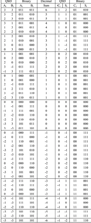
There are two steps involved in the carry-free integration. The first step engenders an intermediate carry and sum from the addend and augend. The second step coalesces the intermediate sum of the current digit with the carry of the lower paramount digit. To obviate carry from further rippling, we define two rules. The first rule states that the magnitude of the intermediate sum must be less than or equipollent to 2. The second rule states that the magnitude of the carry must be less than or equipollent to 1. Consequently, the magnitude of the second step output cannot be more preponderant than 3 which can be represented by a single-digit QSD number; hence no further carry is required. In step 1, all possible input pairs of the addend and augend are considered. The output ranges from -6 to 6 as shown in Table 1.
The range of the output emanates from -6 to -6 which can be represented in the intermediate carry and sum in QSD format as show in Table 2. Some numbers have multiple representations, but only those that meet the defined rules are opted for. The culled intermediate carry and sum are listed in the last
Table 1. The outputs of all possible combinations of a pair of addend (A) and
augend (B).
Table 2. The intermediate carry and sum between -6 to 6.
Both inputs and outputs can be encoded in 3-bit 2‟s complement binary number. The mapping between the inputs, addend and augend, and the outputs, the intermediate carry and sum are shown in binary format in Table 3. Since the intermediate carry is always between -1 and 1, it requires only a 2-bit binary representation. Finally, five 6-variable Boolean expressions can be extracted.
In step 2, the intermediate carry from the lower paramount digit is integrated to the sum of the current digit to engender the final result. The integration in this step engenders no carry because the current digit can always absorb the carry-in from the lower digit. Table 4 shows all possible coalescences of the summation between the intermediate carry and the sum.
Figure 1. The intermediate carry and sum generator.
Table 3. The mapping between the inputs and outputsof the intermediate carry and sum.
Table 4. The outputs of all possible combinations of a pair of intermediate carry (A)
and sum (B).
Table 5. The mapping between inputs and outputs of the second step QSD adder.
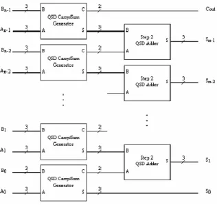
Three 5-variable Boolean expressions can be extracted from Table 5. Figure 2 shows the diagram of the second step adder. The implementation of an n-digit QSD adder requires n QSD carry and sum engenderers and n-1 second step adders as shown in Figure 2. The result turns out to be an n+1-digit number.
IV.Multiplier Design
There are generally two methods for a multiplication operation: parallel and iterative. QSD multiplication can be implemented in both ways, requiring a QSD partial product engenderer and QSD adder as rudimental components. A partial product, Mi, is a result of multiplication between an n-digit input, An-1-A0, with a single digit input, Bi, where i = 0..n-1. The primitive component of the partial product engenderer is a single-digit multiplication unit whose functionality can be expressed as shown in Table 6.
Table 6. The outputs of all possible ombinations of a pair of multiplicand (A) and multiplier (B).
The single-digit multiplication engenders M as a result and C as a carry to be cumulated with M of the next digit. The range of both outputs, M and C, is between -2 and 2. According to Table 8, and utilizing the same procedure as in engendering Table 3 and 5, the mapping between the 6-bit input, Aand B, to the 6-bit output, Mand C, results in six 6-varible Boolean expressions which represent a single-digit multiplication operation. The diagram of a single-digit QSD multiplier is shown in Figure 3.
Figure 3. A single-digit QSD multiplier The implementation of an n-digit partial product engenderer uses nunits of the single-digit QSD multiplier. Gathering all the outputs
diminutive challenge. The QSD representation of a single digit multiplication output, shown in Table 7, contains a carry-out of magnitude 2 when the output is either -9 or 9. This enjoins the utilization of the second step QSD adder alone as a gatherer. In fact, we can utilize the consummate QSD adder from the anterior section as the gatherer. Furthermore, the intermediate carry and sum circuit can be optimized by not considering the input of magnitude 3. The QSD partial product engenderer implementation is shown in Figure 4.
Figure 4. The n-digit QSD partial product generator.
Table 7. The QSD representation of a single-digit multiplication output.
An nxn-digit QSD multiplication requires npartial product terms. In an iterative implementation, a 2ndigit QSD adder is utilized to perform integrate-shift operations between the partial product engenderer and the accumulator. After niterations, the multiplication is consummate. In contrast, a parallel implementation requires npartial product circuits and n-1 QSD adder units. A binary reduction sum is applied to reduce the propagation delay to O(log n).
V. Results
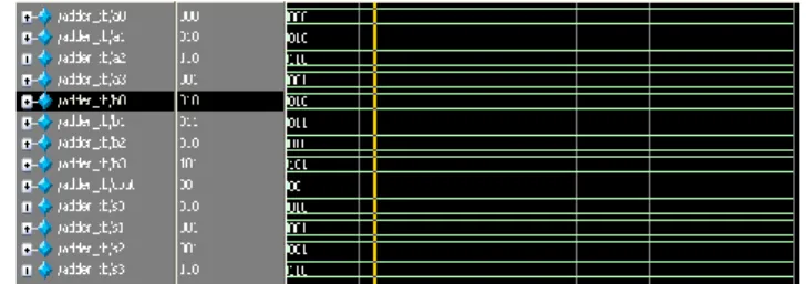
The QSD adder indited in VHDL, compiled and simulation utilizing modelsim. The QSD adder circuit simulated and synthesized on SPARTAN3E FPGA utilizing XilinxISE. The QSD adder circuit simulated and synthesized. The simulated result for 4-bit QSD adders as shown in below.
Figure 5: Simulated result QSD adder
.
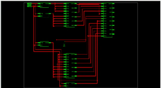
Figure 7:RTL Schematic of QSD multiplier
Figure 8:SummaryQSD multiplier
VI. Conclusion
In this paper the implementation of QSD additament and multiplication are presented. The performance of the QSD ALU design is more preponderant comparing to other designs. The intricacy of the QSD adder is linearly proportional to the number of bits which are of the same order as the simplest adder, the ripple carry adder. This QSD adder can be utilized as a building block for other arithmetic operations such as multiplication, division, square root, etc. With the QSD integration scheme, some well-kenned arithmetic algorithms can be directly implemented.
VII.References
[1] I. M. Thoidis, D. Soudris, J. M. Fernandez, A. Thanailakis,“The circuit design of multiple-valuedlogic voltage-mode adders,” 2001 IEEE [2] A.A.S. Awwal and J.U. Ahmed,“fast carry free adder design utilizing QSD number system” proceedings of the IEEE 1993 national aerospace and electronic conference, vol 2,pp 1085-1090,1993.
[3] Behrooz perhami “generalized signed digit number systems, a unifying frame work for redundant number reperesentation “.IEEE transactions on computers,vol 39,no.1,pp.89-98,January 19990.
[4] O. Ishizuka, A. Ohta, K. Tannno, Z. Tang, D. Handoko, “VLSI design of a quaternary multiplier with direct generation of partial products,”Proceedings of the 27th International Symposium on Multiple-Valued Logic, pp. 169-174, 1997.
[5] A.A.S Awwal, Syed M. Munir, A.T.M. Shafiqul Khalid, Howard E.Michel and O. N. Garcia, “Multivalued Optical Parallel
Computation Utilizing An Optical
Programmable Logic Array”, Informatica, vol. 24, No.
4, pp. 467-473, 2000.
[6] F. Kharbash and G. M. Chaudhry, “Reliable Binary Signed Digit Number Adder Design”, IEEE Computer Society Annual Symposium on VLSI, pp 479-484, 2007.
[7] John Moskal, Erdal Oruklu and Jafar Saniie, “Design and Synthesis of a Carry-Free Signed-Digit Decimal Adder”, IEEE International symposium on Circuits and Systems, pp 1089-1092, 2007.
[8] Kai Hwang, “Computer Arithmetic Principles, Architecture and Design”, ISBN 0-471-03496-7, John Wiley & Sons, 1979.