3358 All Rights Reserved © 2016 IJSETR
An Observer-Based Optimal Voltage Control Scheme
for Three-Phase UPS Systems using Fuzzy Logic
Prasanthi Morugu1 and Prof. G.V.Marutheswar2
1PG student,Department of Electrical and Electronics Engineering, S.V.University , Tirupathi, India
2professor, Department of Electrical and Electronics Engineering, S.V.University, Tirupathi, India
---***---
Abstract –
This paper proposes a simple optimal voltage
control method for three-phase uninterruptible-power-supply systems. An UPS also known as uninterruptable power supply, or battery/flywheel backup is an electrical apparatus that provides emergency power to a load when the input power source or mains power fails. AC voltage controller electronic module based on either thyristors, TRIACs, SCRs or IGBTs, which converts a fixed voltage, fixed frequency alternating current (AC) electrical input supply to obtain variable voltage in output delivered to a resistive load. The proposed voltage controller is composed of a feedback control term and a compensating control term. The former term is designed to make the system errors converge to zero, whereas the latter term is applied to compensate for the system uncertainties. Moreover, the optimal load current observer is used to optimize system cost and reliability. Particularly, the closed-loop stability of an observer-based optimal voltage control law is mathematically proven by showing that the whole states of the augmented observer-based control system errors exponentially converge to zero. Unlike previous algorithms, the proposed method can make a tradeoff between control input magnitude and
tracking error by simply choosing proper
performance indexes. The effectiveness of the proposed controller is validated through simulations on MATLAB/Simulink. Finally, the comparative results for the proposed scheme and the conventional feedbacklinearization control scheme are presented to demonstrate that the proposed algorithm achieves an excellent performance such as fast transient response, small steady-state error, and low total harmonic distortion under load step change, unbalanced load, and nonlinear load with the parameter variations. A fuzzy logic controller to improve the voltage total harmonic distortions and steady state and transient
state responses to get less harmonic distortions than fuzzy less observer voltage controller.
Key Words:
Optimal load current observer, optimal voltage
control, three-phase inverter, total harmonic distortion
(THD), uninterruptible power supply (UPS), fuzzy logic controller.
1. INTRODUCTION
A UPS differs from an auxiliary or emergency power system or standby generator in that it will provide near-instantaneous protection from input power interruptions, by supplying energy stored in batteries, supercapacitors,
or flywheels. The onbattery runtime of most
uninterruptible power sources is relatively short (only a
few minutes) but sufficient to start a standby power
source or properly shut down the protected equipment. Recently, the importance of the UPS systems has been intensified more and more due to the increase of sensitive and critical applications such as communication systems,
medical equipment, semiconductor manufacturing
systems, and data processing systems [1]-[3].
Uninterruptible power supply (UPS) systems supply emergency power in case of utility power failures. These applications require clean power and high reliability regardless of the electric power failures and distorted utility supply voltage. Thus, the performance of the UPS systems is usually evaluated in terms of the total harmonic distortion (THD) of the output voltage and the transient/steady state responses regardless of the load conditions: load step change, linear load and nonlinear load.[4]-[7].
So far, the optimal control theory has been researched in various fields such as aerospace, economics, physics, and so on [8], since it has a computable solution called a performance index that can
3359 All Rights Reserved © 2016 IJSETR
quantitatively evaluate the system performance by contrast with other control theories. In addition, the optimal control design gives the optimality of the controller according to a quadratic performance criterion and enables the control system to have good properties such as enough gain and phase margin, robustness to uncertainties, good tolerance of nonlinearities, etc. [9]. Hence, a linear optimal controller has not only a simple structure in comparison with other controllers but also a remarkable control performance similar to other nonlinear controllers [10]–[12]. Compared to number of control algorithms that have been proposed such as proportional–integral (PI) control,
H∞ loop-shaping control, model predictive control,
deadbeat control, sliding-mode control, repetitive control, adaptive control, and feedback linearization control (FLC) the proposed optimal voltage control and fuzzy based control is showing better performances in voltage correction and reduction of total harmonic distortions(THD). This paper proposes an observer-based optimal voltage control scheme for three-phase UPS systems. This proposed voltage controller encapsulates two main parts: a feedback control term and a compensating control term. The former term is designed to make the system errors converge to zero, and the latter term is applied to
estimate the system uncertainties
Fig.1.Three-phase inverter with an LC alters for a UPS system.
The Lyapunov theorem is used to analyze the stability of the system. Specially, this paper proves the closed loop stability of an observer based optimal voltage control law by showing that the system errors exponentially converge to zero. Moreover, the proposed control law can be systematically designed taking into consideration a tradeoff between control
input magnitude and tracking error unlike previous algorithms.
In FLC, basic control action is determined by a set of linguistic rules. These rules are determined by
the system. Since the numerical variables
areconverted into linguistic variables, mathematical modeling of the system is not required in FC 2. SYSTEM DESCRIPTION AND PROBLEM FORMULATION:
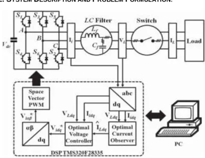
Fig.2. Block diagram of the proposed observer-based optimal voltage control system.
Fig. 2 illustrates the overall block, of the proposed observer-based optimal voltage control system. In practice, the inverter phase currents and line-to-neutral load voltages are measured via the CTs and PTs to implement the feedback control. In this paper, a space vector PWM technique is used to generate the control inputs (Viα and Viβ) in real time. The main objective of
static power converters is to produce an ac output waveform from a dc power supply. According to the type of ac output waveform, these topologies can be considered as voltage source inverters (VSIs), where the independently controlled ac output is a voltage waveform. These structures are the most widely because they naturally behave as voltage sources as required by many industrial applications, such as adjustable speed drives(ASDs), which are the most popular application of inverters. Here we are using an LC filter to filter the harmonics. The proposed algorithm is verified through two different types of loads as explicitly depicted in Fig. 3(a). linear-load circuit that consists of a resistor per phase, where as 3(b) nonlinear-load circuit that is comprised of a three-phase full-bridge diode rectifier, an inductor (Lload), a
3360 All Rights Reserved © 2016 IJSETR
capacitor (Cload), and a resistor (Rload). Using these
loads we depict the performance of the sytem. Along with these an improved technique using fuzzy logic has been implememted to get better results as optimal voltage controller.
Fig. 3. Two types of load circuits. (a) Resistive linear load. (b) Nonlinear load with a three-phase diode rectifier.
Based on Fig. 1, the dynamic model of a three-phase
invertercan be derived in a d − q synchronous
reference frame as follows [13]:
2 2 id iq id Ld i wi k v k v , vLd wvLqk i1id k i1Ld 2 2 iq id iq Lq i wi k v k v ,vLq wvLd k i1iqk i1Lq
where k1 = 1/Cf , and k2 = 1/Lf . In system model (1), vLd,vLq, iid, and iiq are the state variables, and vid and
viq are the control inputs. In this scheme, the
assumption is made to construct the optimal voltage controller and optimal load current observer as follows:
1) The load currents (iLd and iLq) are unknown and
vary very slowly during the sampling period [11].
3. PROPOSED OPTIMAL VOLTAGE CONTROLLER DESIGN AND STABILITY ANALYSIS:
A. Optimal Voltage Controller Design:
Here, a simple optimal voltage controller is proposed for system (1). First, let us define the d − q-axis inverter current references (iid,iiq) as
1 1 1 1 , id Ld Lq iq Lq Ld i i wv i i wv k k (2)
Then, the error values of the load voltages and inverter currents are set as
, de Ld Ld qe Lq Lq v v v v v v , de id id qe iq id i i i i i i (3)
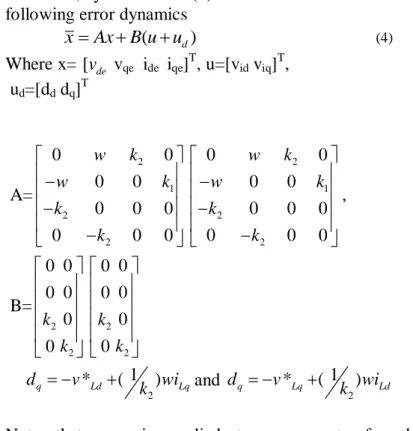
Therefore, system model (1) can be transformed into the following error dynamics
xAx B u u ( d) (4) Where x= [v vde qe ide iqe]T, u=[vid viq]T, ud=[dd dq]T A= 2 1 2 2 0 0 0 0 0 0 0 0 0 0 w k w k k k 2 1 2 2 0 0 0 0 0 0 0 0 0 0 w k w k k k , B= 2 2 0 0 0 0 0 0 k k 2 2 0 0 0 0 0 0 k k 2 1 * ( ) q Ld Lq d v wi k and 2 1 * ( ) q Lq Ld d v wi k
Note that ud is applied to compensate for the
system uncertainties as a compensating term.Consider the following Riccati equation for the solution matrix P [14]:
PA+ATP-PBR-1BTP+Q=0 (5) where Q and R are the positive definite weighting matrices with sufficient dimensions
Remark 1: Recall that Q and R are the weighting
matrices excessive large error or control input values can be penalized by using properly chosen Q and R.
Generally, the large Q means a high control
performance, whereas the large R means a small input magnitude. Consequently, there is a tradeoff between Q and R in the control system. The Q and R parameters generally need to be tuned until satisfactory control results are obtained.
Let the diagonal matrices Q and R be defined as
Q= 1 2 0 0... 0 0 0... 0 ... .... ... ... 0 ... ... m Q Q Q
3361 All Rights Reserved © 2016 IJSETR
R= 1 2 0 0... 0 0 0... 0 ... .... ... ... 0 ... ... K R R R
where Q and R have positive diagonal entries such
that √Qi =1/ymaxi , where i = 1, 2, . . .,m, and √Ri =
1/umaxi , where i = 1, 2, . . .,m. The number ymaxi is
the maximally acceptable deviation value for the
ith component of output y. The other quantity max
i
u is the ith component of input u. With an
initial guessed value, the diagonal entries of Q and
R can be adjusted through a trial-and-error
method.
Then, the optimal voltage controller can be designed by the following equation:
u ud Kx (6)
where K = −R-1BTP denotes the gain matrix, and ud and Kx represent a feed forward control term and a
feedback control term, respectively.
Fig. 4. Block diagram of the proposed optimal voltage control scheme.
B. Stability Analysis of Voltage Controller Consider the following Lyapunov function:
(𝑥)=𝑥𝑇𝑃𝑥 (8) From (4)–(6), and (7), the time derivative of V(x) is
given by the following:
1 1 ( ) 2 ( ) 2 ( ) ( 2 ) T T T T T T T T d V x x Px x P A Bk x dx x P A BR B P x x PA A P PBR B P x x Qx
implies that x exponentially converges to zero.
Remark 3: By considering the parameter variations, the state-dependent coefficient matrix A is rewritten as 𝐴′=
A + ΔA, where ΔA means the value of system parameter variations. Thus, (4) can be transformed into the following error dynamics:
1
( ) T( T T )
V x x P A A P Q PBR B P x (9)
If the following inequality holds for the given ΔA:
𝑃Δ𝐴+Δ𝐴T𝑃<𝑃𝐵𝑅-1+𝑄 (10) then V < 0 for all nonzero x. Therefore, the proposed optimal voltage control system can tolerate any parameter variation satisfying(10)
4. OPTIMAL LOAD CURRENT OBSERVER DESIGN AND STABILITY ANALYSIS
A. Optimal Load Current Observer Design
To avoid using current sensors, a linear optimal load current observer is introduced in this algorithm. As seen in (2) and (4), the inverter current references (i*Q and i*d) and feed forward control term (ud) need load current information as inputs. From (1) and the assumption, the following dynamic model is obtained to estimate the load current:
0 0 0 0 0 0 0 x A x B u y C x (11) where xo = [iLdiLqvLdvLq] T, uo = [k1iidk1iiq] T, A0= 1 1 0 0 0 0 0 0 0 0 0 0 0 0 k w k w , B0= 0 0 0 0 010 0 1
Then, the load current observer is expressed as
0 0 0 0 0 0 0 ˆ ˆ ( ˆ ) x A x B u L y C x (12) where ud [dd dq] , x0 = [ iLd iLq vLd vLq]T , andiˆLd ˆ Ld
i and xˆLq xˆLq are estimates of iLd and iLq, respectively.
In addition, L is an observer gain matrix calculated by L=P C R0 0T 01 (13)
and Po is the solution of the following Riccati equation
1
0 0 0 0 0 0 0 0 0 0 0
T T
A P P A P C R C P Q (14)
3362 All Rights Reserved © 2016 IJSETR
matrices with sufficient dimensions. The manner of
choosing Qo and Ro is the same as in Remark 1.
B. Stability Analysis of Load Current Observer The error dynamics of the load current observer can be
obtained as follows:
xe (A LC x ) e. (15)
Define the Lyapunov function as
Vo(xe) = xTeXxe (16)
Where 1 0
X P . Its time derivative along the error
dynamics (19) is represented by the following: 1 0 0 0 0 0 0 1 0 0 0 0 0 0 0 0 0 0 ˆ ( ) 2 ( ) ( 2 ) T T T e e e e T T T e e T e e d V x x Xx x XA XP C R C x dt x X A P P A P C R C P Xx x XQ Xx
This implies that xe exponentially converges to
zero.
4.5. OBSERVER-BASED CONTROL LAW AND CLOSED-LOOP STABILITY ANALYSIS
4.5.1Observer-Based Control Law:
With the estimated load currents achieved from the observer instead of the measured quantities, the inverter current errors and feedforward control term can be obtained as follows:
d u Kx , 1 1 ˆ qe iq Lq Ld i i i wv k 2 1 d Ld Lq d v wv k , 2 1 q Lq Ld d v wv k (17)
Then, (16) can be rewritten as the following equations:
ˆ 1 0 0 0 de de e i i x
ˆ 0 1 0 0 qe qe e i i x
2 0 1 0 0 d d e w d d x k
2 1 0 0 0 q q e w d d x k (18)From (6) and (18), the proposed observer-based control law can be achieved as
u = ud Kx (19)
where
[ de qe de qe]
x v v i i T and ud [dd dq] (20)
B. Closed-Loop Stability Analysis:
For the purpose of analyzing the stability, (20) is rewritten as the following:
u ud KxHxe (21)
Where H=(w/k2)E +KF,
As a result, the design procedure of optimal voltage control law can be summerised:
Step 1) Build system model (1) in the d − q coordinate frame and then derive error dynamics (4) by using system parameters.
Step 2) Set the optimal voltage controller (6) with the
feedforward control term (ud) and feedback control
term (Kx).
Step 3) Define the load current estimation model (13) and build the load current observer (14) by using the Kalman–Bucy optimal observer.
Step 4) Select the observer weighting matrices Qo and Ro
in Riccati equation by referring to Remark 1. Then,
choose the observer gain L in (12) using Qo and Ro
5. FUZZY LOGIC CONTROLLER:
In FLC, basic control action is determined by a set of linguistic rules. These rules are determined by the system. Since the numerical variables are converted into linguistic variables, mathematical modeling of the system is not required in FC.
3363 All Rights Reserved © 2016 IJSETR
The FLC comprises of three parts: fuzzification, interference engine and defuzzification. The FC is characterized as (i). seven fuzzy sets for each input and output. (ii). Triangular membership functions for simplicity. (iii). Fuzzification using continuous universe of discourse. (iv). Implication using Mamdani’s, ‘min’ operator.(v). Defuzzification using the height method.
Fuzzification: Membership function values are assigned to the linguistic variables, using seven fuzzy subsets: NB, NM, NS, ZE, PS, PM, and PB. The partition of fuzzy subsets and the shape of membership CE(k) E(k) function adapt the shape up to appropriate system. The value of input error and change in error are normalized by an input scaling factor.
Table 1: Fuzzy Rules
In this system the input scaling factor has been designed such that input values are between -1 and +1. The triangular shape of the membership function of this arrangement presumes that for any particular E(k) input there is only one dominant fuzzy subset. The input error for the FLC is given as
E(k) = Pph(k)−Pph(k−1)/ Vph(k)−Vph(k−1) (26)
CE(k) = E(k) – E(k-1) (27) Inference Method: Several composition methods such as Max–Min and Max-Dot have been proposed in the literature. In this paper Min method is used. The output membership function of each rule is given by the minimum operator and maximum operator. Table 1 shows rule base of the FLC.
Defuzzification: As a plant usually requires a non-fuzzy value of control, a defuzzification stage is needed. To compute the output of the FLC, height
method is used and the FLC output modifies the control output. Further, the output of FLC controls the switch in the inverter. In UPQC, the active power, reactive power, terminal voltage of the line and capacitor voltage are required to be maintained. In order to control these parameters, they are sensed and compared with the reference values. To achieve this, the membership functions of FC are: error, change in error and output.
The set of FC rules are derived from u=-[αE + (1-α)*C]
5. PERFORMANCE VALIDATIONS
A. Testbed Description:
The proposed observer-based optimal voltage controller has been performed through both simulations with MATLAB/Simulink . Moreover, the conventional FLC scheme [14] is also adopted to exhibit analysis of the proposed control scheme since it reveals a reasonable performance for nonlinear load and has the circuit model of a three-phase inverter similar to our system. In the testbed, the inverter phase currents and line-to-neutral load voltages are measured via the CTs and PTs to implement the feedback control. In this paper, a space
vector PWM technique is used to generate the control
inputs (Viα and Viβ) in real time. The proposed algorithm
is verified through two different types of loads as explicitly depicted in Fig. 3.More specifically, Fig. 3(a) shows a linear-load circuit that consists of a resistor per phase, whereas Fig. 3(b) depicts a nonlinear-load circuit that is comprised of a three-phase full-bridge diode rectifier, an inductor (Lload), a capacitor (Cload), and a
resistor (Rload). Note that during simulation and the
experiment, observer gain L and controller gain K are selected based on Remark 1 as
L= 105 1.0029 0.003 0.0003 1.0029 1.1877 0 0 1.1877 , K=1011 0.3241 0 3.1623 0 0 0.3241 0 3.1623
B.Simulation and Experimental Results:
The proposed voltage control algorithm is carried
out in various conditions (i.e., load step change, unbalanced load, and nonlinear load) to impeccably expose its merits. In order to instantly engage and
3364 All Rights Reserved © 2016 IJSETR
disengage the load during a transient condition, the on–off switch is employed as shown in Fig. 3.The resistive load depicted in Fig. 4(a) is applied under both the load step change condition (i.e., 0%–100%) and the unbalanced load condition (i.e., phase B opened) to test the robustness of the proposed scheme when the load is suddenly disconnected. In practical applications, the most common tolerance variations of the filter inductance (Lf ) and filter
capacitance (Cf ), which are used as an output filter,
are within ±10%. To further justify the robustness under parameter variations, a 30% reduction in both
Lf and Cf is assumed under all load conditions such as
load step change, unbalanced load, and nonlinear load. Time(s) (a) Time(s) (b)
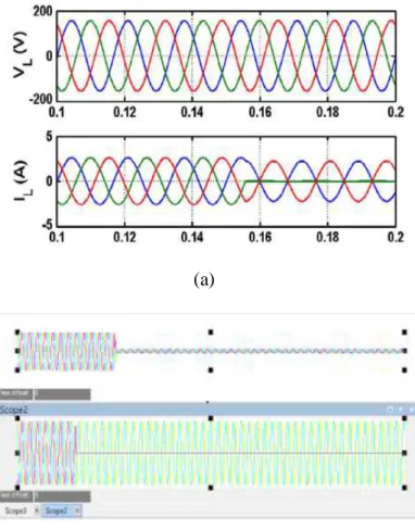
Fig. 6. Simulation and experiment results of proposed observer based control using linear load (a)simulation (b)experiment
This Fig. 6 shows the simulation and experimental results of the proposed control method during the load step change. Moreover, Specifically, the figures display the load voltages (First waveform:
VL), load currents (Second waveformJ(IL).
(a)
Time(s) (b)
Fig.7. simulation results of proposed optimal scheme using nonlinear load
It is important to note that the load current error waveform in the results of the conventional FLC method is not included because the FLC scheme does not need load current information. It can be observed in Fig. 6 that when the load is suddenly changed, the load output voltage presents little distortion. However, it quickly returns to a steady-state condition in 1.0 ms, as shown in the simulation results in Fig. 6(a). Moreover, it has revealed a fast recovery time of 1.5 ms in a real experimental setup as shown in Fig. 6(b).
It can be observed that the load root mean square (RMS) voltage values in both schemes are appropriately regulated at steady state. Moreover, small load current error (ieLA) between the measured value (iLA) and the
3365 All Rights Reserved © 2016 IJSETR
Time(s)
(b)
Fig 8. Combined linear and nonlinear loads (a)simulation (b) experiment without fuzzy
Next, the characteristic performances of the transient and steady state under unbalanced load are verified through Figs. 7. Precisely, this case is implemented under a full-load condition by suddenly opening phase B. It is shown that the load output voltages are controlled well, although the rapid change in the load current of phase B is observed as it is opened, small steadystate voltage errors under unbalanced load are observed because the load RMS voltage values of both methods are almost 110 V. In addition, the load current observer provides high-quality information to the proposed controller . To
evaluate the steady-state performance under
nonlinear load, a three-phase diode rectifier shown in Fig. 7(b) is used.
Fig 9. Combined linear and non linear load with fuzzy
In the case of the conventional FLC scheme, the
corresponding load voltage THD values are 4.4% . It can be also observed that the proposed control strategy provides a better load voltage regulation in steady state similarly as the conventional FLC method. In Fig. 8, it can be evidently seen that the load current observer guarantees a good estimation performance because of a
small load current error (ieLA). Finally, all THD and load
RMS voltage values under the three load conditions. On
the other hand, the THD values of the load output voltage at steady-state full-load operation are found as 4.4% for proposed optimal voltage controller without using FLC and 3.02% for optimal voltage controller using fuzzy logic controller. However, the conventional FLC scheme shows better performance as well as proposed optimal
voltage controller. Therefore, it is explicitly
demonstrated that the proposed algorithm attains lower THD and also the optimal controller using fuzzy logic. The proposed optimal voltage controller with fuzzy has a little bit better performance than the optimal voltage controller without fuzzy.
6.Conclusion:
This paper has proposed a simple observer-based optimal voltage control method of the three-phase UPS systems The proposed controller is composed of a feedback control term to stabilize the error dynamics of the system and a compensating control term to estimate the system uncertainties. Moreover, the optimal load current observer was used to optimize system cost and reliability. This paper proved the closed-loop stability of an observer-based optimal voltage controller by using the Lyapunov theory. Furthermore, the proposed voltage
3366 All Rights Reserved © 2016 IJSETR
control law can be methodically designed taking into account a tradeoff between control input magnitude and tracking error unlike previous algorithms. The superior performance of the proposed control system
was demonstrated through simulations and
experiments. Under three load conditions (load step change, unbalanced load, and nonlinear load), the proposed control scheme revealed a better voltage tracking performance such as lower THD, smaller steady-state error, and faster transient response. The optimal voltage controller that has fuzzy logic controller has attained a better performance as compared to optimal voltage controller without having fuzzy logic circuit with less harmonic distortions in voltage.
REFERENCES:
[1] A. Nasiri, “Digital control of three-phase series-parallel uninterruptible power supply systems,” IEEE
Trans. Power Electron., vol. 22, no. 4, pp. 1116–
1127, Jul. 2007.
[2] Y. H. Chen and P. T. Cheng, “An inrush current
mitigation technique for the line-interactive
uninterruptible power supply systems,” IEEE Trans.
Ind. Appl., vol. 46, no. 4, pp. 1498–1508, May/Jun.
2010.
[3] K. S. Low and R. Cao, “Model predictive control of parallel-connected inverters for uninterruptible power supplies,” IEEE Trans. Ind. Electron., vol. 55, no. 8, pp. 2884–2893, Aug. 2008.
[4] A. Mokhtarpour, H. A. Shayanfar, M. Bathaee, and M. R. Banaei, “Control of a single phase unified power quality conditioner-distributed generation based input output feedback linearization,” J. Elect.
Eng. Technol., vol. 8, no. 6, pp. 1352–1364, Nov.
2013.
[5] J. H. Lee, H. G. Jeong, and K. B. Lee, “Performance improvement of gridconnected inverter systems under unbalanced and distorted grid voltage by using a PR controller,” J. Elect. Eng. Technol., vol. 7, no. 6, pp. 918–925, Nov. 2012.
[6] H. K. Kang, C. H. Yoo, I. Y. Chung, D. J. Won, and S. I. Moon, “Intelligent coordination method of multiple distributed resources for harmonic current compensation in a microgrid,” J. Elect. Eng.
Technol., vol. 7, no. 6,
pp. 834–844, Nov. 2012.
[7] C. Salim, B. M. Toufik, and G. Amar, “Harmonic current compensation based on three-phase three-level shunt active filter using fuzzy logic current controller,” J.
Elect. Eng. Technol., vol. 6, no. 5, pp. 595–604,
Sep. 2011.
[8] T. D. Do, S. Kwak, H. H. Choi, and J. W. Jung, “Suboptimal control scheme design for interior permanent-magnet synchronous motors: An SDRE-based approach,” IEEE Trans. Power Electron., vol. 29, no. 6, pp. 3020–3031, Jul. 2013.
[9] F. Lin, Robust Control Design: An Optimal Control
Approach. Chichester, U.K.: Wiley, 2007.
[10] C. Olalla, R. Leyva, A. E. Aroudi, and I. Queinnec, “Robust LQR control for PWM converters: An LMI approach,” IEEE Trans. Ind. Electron., vol. 56, no. 7, pp. 2548–2558, Jul. 2009.
[11] P. Rao, M. L. Crow, and Z. Yang, “STATCOM control for power system voltage control applications,”
IEEE Trans. Power Del., vol. 15, no. 4, pp. 1311–1317,
Oct. 2000.
[12] Y. S. Rao and M. C. Chandokar, “Real-time electrical load emulator using optimal feedback control technique,” IEEE Trans. Ind. Electron., vol. 57,
no. 4, pp. 1217–1225, Apr. 2010.
[13] H. Tao, J. L. Duarte, andM. A.M. Hendrix, “Line-interactive UPS using a fuel cell as the primary source,”
IEEE Trans. Ind. Electron., vol. 55, no. 8, pp. 3012–
3021,Aug.2008.
[14] D. E. Kim and D. C. Lee, “Feedback linearization control of three-phase,” IEEE Trans. Ind. Electron., vol.