DEVELOPING PRINTÒ DRY POWDERS FOR PULMONARY PROTEIN DELIVERY
Erin Michelle Wilson
A dissertation submitted to the faculty at the University of North Carolina at Chapel Hill in partial fulfillment of the requirements for the degree of Doctor of Philosophy in the Division of
Pharmacoengineering and Molecular Pharmaceutics in the Eshelman School of Pharmacy.
Chapel Hill 2017 Approved by: Joseph DeSimone Philip Smith David Henke J. Christopher Luft Michael Jay Michael Miley
Ó 2017 Erin Michelle Wilson ALL RIGHTS RESERVED
ABSTRACT
Erin Michelle Wilson: Developing PRINTÒ Dry Powders for Pulmonary Protein Delivery (Under the direction of Joseph DeSimone)
Pulmonary delivery is an attractive route of administration that can be used for the local delivery of therapeutics for respiratory conditions or to non-invasively deliver sufficiently low molecular weight therapeutics to systemic circulation. There is a particular interest in protein delivery, however, many respirable formulations are inefficient at delivering therapeutics to the desired region of the lungs, which precludes the development of costly biologics for inhalation. Particle engineering, a strategy that aims to rationally and precisely control particle size, shape, density, and composition, has been utilized to design high-performance dry powder aerosols that deposit efficiently and precisely in the desired area of the lungs. However, current fabrication methods offer limited control of particle geometry and impose unfavorable stresses on proteins during manufacturing.
The overall goals of this dissertation were to fabricate and characterize protein-based microparticles with Particle Replication In Non-wetting Templates (PRINT) technology and engineer these particles into high-performance protein dry powder aerosols. We hypothesized that the precise control of particle geometry afforded by PRINT along with the low physical stress imparted by the process would allow for the stable incorporation of proteins into precisely engineered particles, resulting in high-performance protein dry powder aerosols.
A generalizable formulation strategy to micromold a variety of proteins into precisely engineered PRINT particles was developed, and the incorporated proteins were found to retain
their native structure and function. Following lyophilization into dry powders, these formulations were found to fluidize, aerosolize, and deposit with high efficiency and precision. We then expanded the formulation strategy to fabricate multiple PRINT particle shapes, which were used to explore the impact of particle shape on dry powder performance in an effort to inform and improve particle engineering strategies. Informed by the formulation development and particle shape studies, dry powder formulations of two therapeutic proteins were developed and the delivery of one formulation was demonstrated in vivo. Overall, we have demonstrated the utility of PRINT as a platform to manufacture high-performance protein dry powders and we have furthered understanding of the impact of particle shape on aerosol performance, both of which contribute to the advancement of particle engineering strategies for inhalable formulations.
ACKNOWLEDGEMENTS
I would like to thank my advisor, Joseph DeSimone, for the opportunity to work in a transformative environment, where he continuously inspired and encouraged the application of our research to real-world problems. He changed the way I both view and approach research, and for that I will be forever grateful. I would also like to thank Chris Luft for his direction and support, constant accessibility, and his inherent ability to be a motivator. I would like to thank my committee members, Philip Smith, David Henke, Michael Jay, and Michael Miley for their time, advice, and guidance that aided in both the progression and quality of my research. Thank you to all of the DPMP faculty, staff, and students who have been invaluable in my growth as both a scientist and a person throughout graduate school.
I would also like to acknowledge the outstanding core facilities at UNC and their even more outstanding staff – Amar Kumbhar and Wallace Ambrose at CHANL, Bob Bagnell, Victoria Madden, and Kristen White at the MSL, Ashutosh Tripathy at the Mac-in-Fac, and Charlene Santos, Mark Ross, and Alain Valdivia at the Animal Studies Core Facility.
Thank you to all of the DeSimone lab members I had the pleasure of working with throughout graduate school. I would particularly like to thank the DTRA team – Ashley, Cassie, Katie, and Tojan – for their friendship, support, and constant willingness to help. In addition, I’d like to thank Jason, Jillian, Chintan, Tammy, Cathy, Cameron for their help with experimental design and instrument training.
Finally, I would like to thank my family for their unwavering support in everything I do. I couldn’t have done it without you!
TABLE OF CONTENTS
LIST OF TABLES ... xi
LIST OF FIGURES ... xi
LIST OF ABBREVIATIONS AND SYMBOLS ... xiv
CHAPTER 1: INTRODUCTION TO PULMONARY DRUG DELIVERY ... 1
1.1 Overview of Drug Delivery ... 1
1.2 Structure and Function of the Human Respiratory Tract ... 2
1.2.1 Structure and Function of the Airway Epithelium ... 4
1.3 Aerosol Delivery to the Lungs ... 5
1.3.1 Target of Aerosol Deposition ... 5
1.3.2 Aerodynamic Diameter ... 6
1.3.3 Aerosol Deposition in the Lungs ... 6
1.3.4 Devices for Inhaled Aerosol Delivery ... 9
1.3.5 Aerosol Characterization of Dry Powder Inhalers ... 11
1.4 Particle Fabrication Techniques for Dry Powder Inhalers ... 13
1.4.1 Spray Drying ... 13
1.4.2 Spray Freeze Drying ... 15
1.5 Particle Replication in Non-wetting Templates ... 16
1.6 Overview of Dissertation ... 17
CHAPTER 2: HIGH-PERFORMANCE PRINT DRY POWDER AEROSOLS FOR
PULMONARY PROTEIN DELIVERY ... 23
2.1 Introduction ... 23
2.2 Materials and Methods ... 26
2.2.1 Materials ... 26
2.2.2 Methods... 26
2.3 Results ... 31
2.3.1 Fabrication of Respirable PRINT Protein Particles ... 31
2.3.2 Characterization of Protein Stability ... 34
2.3.3 In Vitro Aerosol Characterization ... 38
2.4 Discussion ... 41
2.5 Conclusions ... 47
References ... 49
CHAPTER 3: THE ROLE OF PARTICLE SHAPE IN FLOWABILITY, AEROSOLIZATION, AND DEPOSITION OF DRY POWDER FORMULATIONS ... 53
3.1 Introduction ... 53
3.2 Materials and Methods ... 54
3.2.1 Materials ... 54
3.2.2 Methods... 55
3.3 Results ... 59
3.3.1 Fabrication and Characterization of Lysozyme Particle Shapes ... 59
3.3.2 Characterization of Bulk Powder Properties ... 63
3.3.3 Aerosol Characterization of Lysozyme Particle Shapes ... 64
3.4 Discussion ... 69
3.5 Conclusions ... 75
References ... 77
CHAPTER 4: THERAPEUTIC APPLICATIONS OF PRINT DRY POWDERS ... 80
4.1 Introduction ... 80
4.2 Materials and Methods ... 82
4.2.1 Materials ... 82
4.2.2 Methods... 83
4.3 Results ... 86
4.3.1 Fabrication and Characterization of DNase 1 µm Cylinders ... 86
4.3.2 Characterization of DNase Stability ... 88
4.3.3 In Vitro Aerosol Characterization of DNase 1 µm Cylinders ... 90
4.3.4 Fabrication and Characterization of PRINT BuChE Particles ... 91
4.3.5 In Vitro Aerosol Characterization of BuChE 1 µm Cylinders ... 93
4.3.6 Insufflation of BuChE 1 µm Cylinders ... 94
4.4 Discussion ... 97
4.5 Conclusions ... 104
References ... 106
CHAPTER 5: SUMMARY AND FUTURE DIRECTIONS ... 109
5.1 Summary ... 109
5.2 Impact and Future Directions ... 110
5.2.3 Therapeutic Applications of PRINT Protein Dry Powders ... 116 5.3 Outlook ... 118 References ... 119
LIST OF TABLES
Table 2.1 DOE for roll-to-roll BSA 1 µm cylinders ... 34
Table 2.2 Aerosol parameters of lyophilized BSA and lysozyme 1 µm cylinders from an insufflator ... 39
Table 2.3 Aerosol parameters of lyophilized BSA and lysozyme 1 µm cylinders from an inhaler ... 41
Table 3.1 Particle dimensions ... 61
Table 3.2 Surface area and volume of particle shapes ... 61
Table 3.3 Shape descriptor values ... 61
Table 3.4 Angle of repose of lysozyme particle shapes ... 63
Table 3.5 Density and compressibility of lysozyme particle shapes ... 64
Table 3.6 Aerosol parameters of lysozyme particle shapes ... 65
Table 4.1 Aerosol parameters of DNase 1 µm cylinders ... 91
Table 4.2 Aerosol parameters of BuChE 1 µm cylinders ... 94
LIST OF FIGURES
Figure 1.1 Diagram of generations of bifurcating airways ... 3
Figure 1.2 Diagram of progression of respiratory epithelium structure ... 4
Figure 1.3 Diagram of airway flow velocity by generation ... 7
Figure 1.4 Region of particle deposition ... 8
Figure 1.5 Classes of inhaled devices ... 9
Figure 1.6 Particle pathway through cascade impactor ... 12
Figure 1.7 Spray dryer diagram ... 14
Figure 1.8 Particle engineering with spray drying ... 14
Figure 1.9 Methods of droplet freezing ... 15
Figure 1.10 PRINT schematic ... 16
Figure 2.1 Formulation optimization of lysozyme 1 µm cylinders ... 31
Figure 2.2 SEM of dry powders of BSA and lysozyme 1 µm cylinders ... 32
Figure 2.3 SEM of lyophilized BSA and lysozyme 1 µm cylinders ... 32
Figure 2.4 SEM of BSA 80x320 nm rods ... 32
Figure 2.5 Composition of lyophilized BSA and lysozyme 1 µm cylinders ... 33
Figure 2.6 Composition of lyophilized BSA and lysozyme 1 µm cylinders ... 33
Figure 2.7 SEM of roll-to-roll BSA 1 µm cylinders ... 34
Figure 2.8 SDS-PAGE of lyophilized BSA and lysozyme 1 µm cylinders ... 35
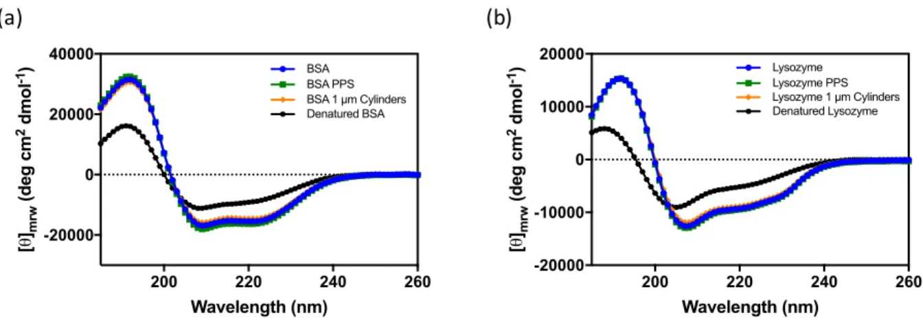
Figure 2.9 Circular dichroism of lyophilized BSA and lysozyme 1 µm cylinders ... 36
Figure 2.10 Secondary structure of lyophilized BSA and lysozyme 1 µm cylinders ... 36
Figure 2.11 Intrinsic fluorescence of lyophilized BSA and lysozyme
1 µm cylinders ... 37
Figure 2.12 Enzymatic activity of lyophilized lysozyme 1 µm cylinders ... 37
Figure 2.13 SDS-PAGE of lyophilized BSA and lysozyme 1 µm cylinders ... 38
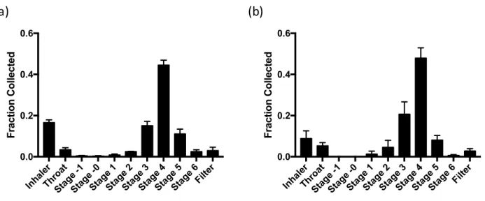
Figure 2.14 Cascade impaction of lyophilized BSA and lysozyme 1 µm cylinders from an insufflator ... 39
Figure 2.15 Cascade impaction of lyophilized BSA and lysozyme 1 µm cylinders from an inhaler ... 40
Figure 3.1 Models of lysozyme particle shapes ... 55
Figure 3.2 Image analysis process ... 56
Figure 3.3 Formulation optimization of lysozyme particle shapes ... 59
Figure 3.4 SEM of lysozyme particle shapes ... 60
Figure 3.5 Particle dimensions ... 60
Figure 3.6 Composition of lyophilized lysozyme particle shapes ... 62
Figure 3.7 Enzymatic activity of lysozyme particle shapes ... 62
Figure 3.8 Powder cones for angle of repose ... 63
Figure 3.9 Cascade impaction of lysozyme particle shapes ... 65
Figure 3.10 Powder parameters as a function of Feret max ... 66
Figure 3.11 Powder parameters as a function of MMAD ... 66
Figure 3.12 Powder parameters as a function of AR ... 67
Figure 3.13 Powder parameters as a function of SA/V ... 67
Figure 3.14 Powder parameters as a function of circularity ... 68
Figure 3.15 Powder parameters as a function of SVMD ... 68
Figure 4.3 SDS-PAGE of DNase 1 µm cylinders ... 88
Figure 4.4 Circular dichroism of DNase 1 µm cylinders ... 89
Figure 4.5 Secondary structure of DNase 1 µm cylinders ... 89
Figure 4.6 Intrinsic fluorescence of DNase 1 µm cylinders ... 90
Figure 4.7 Cascade impaction of DNase 1 µm cylinders ... 91
Figure 4.8 SEM of BuChE 1 µm cylinders ... 92
Figure 4.9 Composition of BuChE 1 µm cylinders ... 92
Figure 4.10 Enzymatic activity of BuChE 1 µm cylinders ... 93
Figure 4.11 SEM of BuChE nanoparticles ... 93
Figure 4.12 Cascade impaction of BuChE 1 µm cylinders ... 94
Figure 4.13 BuChE assay development ... 95
Figure 4.14 IVIS of BuChE 1 µm cylinders ... 96
Figure 4.15 Residence time of BuChE 1 µm cylinders ... 97
Figure 5.1 Examples of PRINT particle shapes ... 111
LIST OF ABBREVIATIONS AND SYMBOLS
2D Two-dimensional
3D Three-dimensional
A Projected area
ACI Andersen cascade impactor AFM Atomic force microscopy ANOVA Analysis of variance
AR Aspect ratio
BAL Bronchoalveolar lavage BALF Bronchoalveolar lavage fluid
BD Biodistribution
BSA Bovine serum albumin BuChE Butyrylcholinesterase CD Circular dichroism CE Capillary electrophoresis CF Cystic fibrosis CI Compressibility index cm Centimeter
COPD Chronic obstructive pulmonary disorder DDS Drug delivery systems
DNase Deoxyribonucleasae I DOE Design of experiments DPI Dry powder inhaler
DSC Differential scanning calorimetry
ED Emitted dose
ELF Epithelial lining fluid
ELSD Evaporative light scattering detector FDKP fumaryl diketopiperazine
FEV Forced expiratory volume FPF Fine particle fraction
GSD Geometric standard deviation GSH Glutathione (reduced)
GSSG Glutathione (oxidized) HDODA Hexanediol diacrylate
HPLC High-performance liquid chromatography HPMC Hydroxypropyl methylcellulose
IACUC Institution of Animal Care and Use Committee IVIS In vivo imaging system
kDa Kilodalton
kPa Kilopascals
L Liter
LC Liquid chromatography
MES 2-(N-morpholino)ethanesulfonic acid
mg Milligram
min Minute
mm Millimeter
MMAD Mass median aerodynamic diameter MWCO Molecular weight cutoff
NHS N-hydroxysuccinimide
nm Nanometer
P Perimeter
PAGE Polyacrylamide gel electrophoresis PBS Phosphate buffered saline
PEG Polyethylene glycol
PET Poly(ethylene terephthalate) PFPE Perfluoropolyether
PK Pharmacokinetics
pMDI Pressurized metered dose inhaler PPS Pre-particle solution
PRINT Particle replication in non-wetting templates psi Pounds per square inch
PVPVA Poly(1-vinylpyrrolidone-co-vinyl acetate) RF Respirable fraction
SA Surface area
SD Spray drying
SDS Sodium dodecyl sulfate
SEC Size exclusion chromatography SEM Scanning electron microscopy
SFD Spray freeze drying
SVMD Surface volume mean diameter
tan Tangent
Tg Glass transition temperature TGA Thermogravimetric analysis
Trp Tryptophan
V Volume
V0 Initial volume
Vf Final volume
wt% Weight percent
xF,max Maximum Feret diameter xF,min Minimum Feret diameter
% Percent
° Degrees
°C Degrees Celsius
⍴bulk Bulk density ⍴tap Tapped density
α Angle of repose
λmax Wavelength of maximum signal
µL Microliter
µm Micrometer
CHAPTER 1: INTRODUCTION TO PULMONARY DRUG DELIVERY
1.1 Overview of Drug Delivery
Conventional oral and parenteral formulations allow therapeutics to diffuse and distribute throughout the body upon entering systemic circulation.1,2 These formulations offer little control over drug distribution, resulting in inefficient drug accumulation at the desired therapeutic site of action and undesirable side effects due to drug accumulation at off-target sites.1–3 Modern drug delivery systems (DDS) aim to alter the biodistribution (BD) and/or pharmacokinetics (PK) of incorporated drugs to improve drug efficacy and minimize side effects.1,2 Advances in
nanotechnology in the last two decades have resulted in the development of several nano- and microfabrication methods.4–7 These fabrication methods have been used to manufacture precisely engineered nano- and microparticle DDS which have the potential to revolutionize medicine.8–10
One popular application of microfabricated particles in drug delivery is pulmonary administration, which can be used for both local and systemic drug delivery.11–15 Direct
administration of therapeutics to the lungs for respiratory conditions localizes drug to the desired site of therapeutic effect, thereby minimizing the required drug dose and systemic exposure to the drug.14,16 Systemic delivery of inhaled therapeutics is possible due to the large alveolar surface area of the lungs, which provides an abundance of capillaries and a direct route of drug absorption into systemic circulation.17 The pulmonary route is particularly promising for protein delivery, as it can be used to locally deliver adequately high doses of protein drugs and to deliver low molecular weight proteins to systemic circulation in a non-invasive manner.12,15,18 Despite
remains limited by poor delivery efficiency and dose consistency.16,19,20 Precisely engineered microfabricated particles provide an excellent opportunity to rationally design respirable formulations and improve the delivery efficiency and deposition precision of inhaled aerosols, which could decrease the costs, dose variability, and side effects associated with current inhaled medicines.14,21
The work presented in this dissertation represents our efforts to develop high-performance aerosols of precisely engineered microfabricated particles. The content of this chapter provides an overview of the structure of the respiratory system, important concepts in pulmonary delivery, and particle fabrication methods. A basic understanding of these concepts is required to develop an improved respirable formulation comprised of engineered particles. 1.2 Structure and Function of the Human Respiratory Tract
Thorough knowledge of the structure and function of the respiratory tract are critical to understanding the impact that airway architecture and transport has on respiratory drug
delivery.18,22 The architecture of the respiratory tract is characterized by extensive bifurcating airways that serve as pathways for gas transport, as shown in Figure 1.1.20,23 These bifurcating airways are divided into two regions based on their functions: the conducting zone and the respiratory zone.17,22 The conducting zone is the upper portion of the respiratory tract and is responsible for transporting gas to and from the respiratory zone.18,20,22 The conducting zone begins in the oral and nasal cavities, progresses through the larynx and trachea, enters the lungs through the bronchi, then continues to the bronchioles and concludes in the terminal
bronchioles.22,23 From the trachea to the terminal bronchioles, the airways in the conducting zone bifurcate approximately 17 times, which progressively increases the surface area of the airways and decreases the velocity of air flow.20,22
Figure 1.1 Diagram of generations of bifurcating airways. Diagram of the generations of bifurcating airways within the human respiratory system from the trachea to the alveolar sacs. Reproduced from Patton and Byron18 with permission.
The respiratory zone, comprised of all airways distal to the terminal bronchioles, bifurcates 6 additional times to form the respiratory bronchioles, alveolar ducts, and alveolar sacs.17,20,22 The respiratory zone is where diffusion of oxygen from the alveoli into the blood and diffusion of carbon dioxide from the blood into the alveoli occurs.18,23 The surface area of the respiratory zone is more than 100 square meters.18 Air is transported in and out of the lungs upon contraction and relaxation of the diaphragm, which changes the volume of the lungs.23 Upon contraction of the diaphragm, the lung volume increases, resulting in new air being drawn into the lungs.22,23 The new air provides the partial pressure gradient necessary to allow gas
exchange.22 Gas exchange is facilitated by both the large surface area and submicron thickness of the alveolar epithelium in the respiratory zone.22,23 Blood re-oxygenated from contact with the
1.2.1 Structure and Function of the Airway Epithelium
In addition to the functional difference between the conducting and respiratory zones, there are major differences in the epithelium structure in the two zones.18 The airway epithelium serves as the final barrier between the contents of the airways and the bloodstream.18,24
Generally, traveling from the bronchi to the alveolar sacs, the thickness of both the epithelium and the epithelial lining fluid (ELF) decreases.18,22 A diagram of the changes in both the structure of the epithelium and the thickness of the ELF are presented in Figure 1.2.
Figure 1.2 Diagram of progression of respiratory epithelium structure. Diagram of the airway epithelium structure of the human respiratory system, including the bronchi, terminal bronchioles, and alveoli. Reproduced from Patton and Byron18 with permission.
From the bronchi until the terminal bronchioles, a ciliated pseudostratified columnar epithelium is present, which is comprised primarily of ciliated cells, goblet cells, and basal cells.18,24,25 The goblet cells produce mucus that is moved upwards by ciliated cells resulting in a
primary route of clearance for insoluble particles deposited in the conducting zone, while soluble particles are generally cleared from the conducting zone by absorptive mechanisms.24
Distal to the terminal bronchioles, the columnar epithelial cells of the conducting zone are absent and are replaced by type 1 cells of submicron thickness.18 Along with the submicron epithelium, the thickness of the layer of ELF is only 70 nm in the respiratory zone, resulting in an extremely thin path for gas diffusion and exchange.22 The thin epithelium in the respiratory zone is protected by several alveolar macrophages for each alveolar sac.17,18,24 The alveolar macrophages are the primary clearance mechanism for insoluble particles in the respiratory region.24 Soluble particles, which largely avoid internalization by macrophages, are primarily removed from the alveolar sacs by absorption to systemic circulation, either intact or following metabolism.18,24 Although some proteins undergo degradation in the alveoli, it is not a major clearance mechanism for the majority of proteins.24,26,27 Both the structure of the airway
epithelium and the resulting predominate clearance mechanism must be considered to rationally design efficacious inhaled formulations.
1.3 Aerosol Delivery to the Lungs 1.3.1 Target of Aerosol Deposition
The complicated architecture of the airways, epithelium structure, lung clearance mechanisms, and the desired site of therapeutic action must all be carefully considered when determining the optimal region of deposition for a respirable formulation.24 The low surface area, long diffusion path, and rapid mucociliary clearance present from the trachea to the terminal bronchioles make the conducting zone a poor target for drug deposition and efficient drug absorption.22,25 Although many common respiratory diseases exert their pathological effect on the conducting airways, the poor absorption potential in the conducting zone precludes efficient
delivery directly to the site of therapeutic need.22,25 Therefore, the ideal deposition target for the majority of therapeutics for both local and systemic delivery is the alveolar region of the
respiratory zone.22,24,25 The large surface area and short diffusion path present in alveoli provides the best opportunity for the absorption of both small molecule and biologic formulations.18 While the alveoli provide an excellent pathway for drug absorption, they also contain alveolar
macrophages, which internalize insoluble drug particles and reduce the bioavailability of drug delivered to the alveoli.18,24,25 Internalization of therapeutics by alveolar macrophages can be avoided by delivering rapidly soluble particles24, particles larger than 5 µm in diameter28,29, or particles with a stealth coating.30,31 Soluble particles deposited in the alveoli can be absorbed into systemic circulation.24
1.3.2 Aerodynamic Diameter
The behavior of a particle as an aerosol is dependent on particle diameter, density, and shape.11 As such, the size of aerosol particles is described as aerodynamic diameter, which is the diameter of a sphere of unit density that has the same settling velocity as the given particle.11 The aerodynamic diameter is frequently used to estimate the site of particle deposition within the respiratory tract.22
1.3.3 Aerosol Deposition in the Lungs
The alveolar region is the ideal target of aerosol deposition for many local and systemic therapies. In order to engineer particulate aerosols that efficiently deposit in the alveolar region, a basic understanding of the mechanisms driving particle deposition is needed. The three
mechanisms by which particle deposition occurs in the respiratory system are impaction,
sedimentation, and diffusion.22,32,33 One major factor, along with aerodynamic diameter, driving particle deposition in the numerous bifurcating airways in the lungs is the rate of air flow through
the airways.33 Generally, air flow decreases in velocity as airways progressively become smaller in diameter at each bifurcation, as modeled in Figure 1.3.24,32,34 Deposition by impaction
generally occurs with particles larger than 2 µm in aerodynamic diameter in the upper airways, where the air flow velocity gives the particles sufficient inertia to exit the air stream and deposit in the airways.22,33 Particles between 0.5 and 2 µm in aerodynamic diameter typically deposit by sedimentation in the respiratory zone, which has a low air flow velocity.22 Sedimentation occurs as a result of the gravitational forces on particles, and particle deposition by sedimentation with particle diameter, particle density, and time available for sedimentation.33 The low flow rate of the respiratory region results in sufficient residence time for particles to deposit by
sedimentation.33 The final mechanism for particle deposition is diffusion, which is dependent on the Brownian motion of particles less than 0.5 µm in aerodynamic diameter in a low flow
region.22 In practice, diffusion is not an efficient mechanism for the deposition of particles in the respiratory region.18
The approximate deposition profile expected for particles from 0 to 15 µm in
aerodynamic diameter is presented in Figure 1.4. As previously stated, particles less than 0.5 µm are expected to deposit by diffusion, particles between 0.5 and 2 µm are expected to deposit by sedimentation, and particles larger than 2 µm are expected to deposit by impaction. Particles between 0.1 and 0.5 µm in aerodynamic diameter are not well-suited for efficient alveolar delivery, as they are largely exhaled.14,20,36 Particles larger than 5 µm in diameter also fail to efficiently accumulate in the alveolar region as a result of extensive mouth and throat impaction, with deposition shifting higher in the respiratory tract with increasing particle aerodynamic diameter.18,20
Figure 1.4 Region of particle deposition. Diagram of the region of deposition for particles from 0 to 15 µm in aerodynamic diameter. Reproduced from Patton and Byron18 with permission.
Optimal deposition in the alveolar region is achieved for aerosols of particles with aerodynamic diameters between 1 and 5 µm.18 Given that the ideal site of deposition for most therapeutics is in the alveolar region, engineered particle formulations should be developed to yield a specific aerodynamic diameter between 1 and 5 µm.22
1.3.4 Devices for Inhaled Aerosol Delivery
Though the history of inhaled aerosol delivery dates back more than 3000 years ago, the development of modern inhaled technologies with strict regulatory requirements began in the past 50 years.22,37 There are three primary classes of these inhaled technologies, including nebulizers, pressurized metered dose inhalers (pMDIs), and dry powder inhalers (DPIs), each of which operate based on unique principles.15,22,38,39 A diagram representative of each device class is presented in Figure 1.5. A fundamental knowledge of each type of aerosol device along with an extensive understanding of the therapeutic to be delivered is required to choose the
appropriate device for aerosol delivery.
Evaporation Aggregation of suspended droplets Baffle Droplet formation Reservoir liquid containing drug
The oldest device is the nebulizer, which uses an external energy source to generate an aerosol from a liquid formulation.38,39 Nebulizers can be used for most liquid formulations and for nearly any patient, as they require minimal patient coordination or skill.38 Nebulizers are also useful for the delivery of therapeutics with a high dose by mass.39 Therapeutic delivery via nebulizers is a burden to the patient, as these devices require treatments that typically last 10-20 minutes, not including the additional time required to disassemble and sanitize the nebulize after each use.22,38 Nebulizers are generally recognized as inefficient in delivering drugs to the lungs, though modern nebulizers have been able to deliver between 30 and 75 % of the emitted dose to the lungs.38,40 Due to the limitations of nebulizers, formulations are typically developed for delivery by nebulizers only if both pMDIs and DPIs are deemed inappropriate for the desired application.39
The development of pMDIs was revolutionary for pulmonary drug delivery, as it was the first highly portable device produced for inhalation.38 pMDIs consist of a solution or suspension of drug in liquid hydrofluorocarbon propellant contained within a pressurized canister.14,22,38 The canister has a metering valve that, upon actuation, releases a controlled volume of liquid
propellant that rapidly equilibrates with the pressure of the atmosphere and forms drug-containing droplets.22 Though pMDIs are convenient for most patients, the high velocity of aerosol emission and the requirement for coordination between device actuation and inhalation results in 50 – 80 % of the emitted dose depositing in the mouth and throat.38,41 Despite the poor delivery efficiency, pMDIs remain common delivery devices that are frequently prescribed due to their portability, low cost, and ability to contain more than 100 doses.38,42 The ability to overlook poor delivery efficiency is likely due to the low dose of drugs commonly delivered by pMDIs, including bronchodilators and corticosteroids, which require only microgram quantities
for therapeutic efficacy.24
The final class of delivery devices is DPIs, which provide an alternative to pMDIs while remaining small and portable.38 DPIs utilize patient inhalation to generate an aerosol from a powder formulation contained within the delivery device.21,39 Because patient inhalation
produces the aerosol, the need for coordination between device actuation and inhalation required with pMDIs is eliminated.21 Additionally, DPIs can be used to deliver milligram quantities of drug as opposed to the microgram quantities possible with pMDIs.38,39 DPIs are particularly compatible with protein formulation, as dried protein formulations are less susceptible to degradation than liquid formulations.15,43 However, the dry powder formulation in DPIs is susceptible to environmental humidity, which causes particles to flow poorly and deagglomerate inefficiently under air flow.38 Inefficient deagglomeration results in premature particle deposition in the mouth and throat.21 Proper packing of DPI formulations is required to minimize the effects of ambient humidity on moisture-sensitive formulations.21
As summarized above, each class of devices for pulmonary delivery has unique strengths and weaknesses which must be carefully considered to determine the ideal device for each new inhaled therapy. The dry powder formulation and increased deliverable doses of DPIs make them an ideal device for pulmonary protein delivery. As this dissertation is focused on the formulation of proteins into dry powders for pulmonary delivery, the remainder of the introduction will focus on the formulation and characterization of dry powder aerosols.
1.3.5 Aerosol Characterization of Dry Powder Inhalers
The fate of inhaled aerosols within the respiratory system can be reasonably predicted by the aerodynamic diameter of particles within the aerosol.22 Aerosol particles with an
the respiratory zone.18 In vitro aerosol characterization must be performed as a step in the development of engineered dry powders to ensure the particles have an aerodynamic diameter between 1 and 5 µm, and thus can be expected to deposit in the alveoli.
Figure 1.6 Particle pathway through cascade impactor. Diagram of the path of particle flow through an Andersen Cascade Impactor. Reproduced from Smyth and Hickey22 with permission.
Cascade impaction is a widely-used technique to determine the aerodynamic diameter of inhaled aerosols.44,45 Cascade impaction directly measures aerodynamic diameter by separating particles on a series of stages based on particle inertia.45 An Andersen Cascade Impactor (ACI) contains eight vertically-stacked stages, each of which consists of a plate with holes of a
specified diameter and arrangement and a collection plate for impacted particles.45 The size and area of the holes decrease with progression through the ACI. The aerosol sample is drawn
through the ACI under air flow, and, as the size of the holes progressively decreases, the velocity of air flow increases.45 A diagram of particle flow through an ACI is presented in Figure 1.6.
that achieve sufficient inertia to deposit by impaction. The result is a separation of particles by aerodynamic diameter on each of the eight stages.
1.4 Particle Fabrication Techniques for Dry Powder Inhalers
Particle engineering is a general strategy of manufacturing particles of optimal physical features, including size, shape, porosity, and density, to improve formulation performance. The application of particle engineering to dry powder formulations aims to decrease particle size polydispersity, improve fluidization and deagglomeration, and optimize drug bioavailability, among other goals.11,46 In this section, two primary methods to produce engineered particles for high-performance dry powder aerosols, spray drying and spray freeze drying, are discussed. Alternative methods to manufacture engineered respirable particles are detailed in Chapter 2. 1.4.1 Spray Drying
Spray drying involves the atomization of a liquid formulation containing drug and excipient into micron-sized droplets followed by rapid drying in a heated gas stream to produce dry particles.11,46 A diagram of the spray drying process is in Figure 1.7. While spray drying can be used to manufacture particles between 1 and 5 µm in aerodynamic diameter, particles this small are pushing the lower limits of spray drying, and thus require extensive particle
engineering for successful production.11 Many different process parameters can be altered to produce optimal particles, such as atomization pressure, feed flow rate and temperature, and drying chamber air flow and temperature.46 For more information on particle engineering in spray drying, readers are referred to two excellent and comprehensive reviews by Reinhard Vehring, which discuss particle formation mechanisms in great detail.46,47 A summary of process conditions used to fabricate engineered particles of differing morphologies in Figure 1.8
Figure 1.7 Spray dryer diagram. Process diagram of the equipment and process of a standard spray drying apparatus. Reproduced from Sosnik and Seremeta48 with permission.
While spray drying has some control of particle size, shape, and density, control is limited to spherical particle morphologies. In addition, spray drying produces a range of particle sizes, which limits the ability of these particles to achieve efficient and precise lung deposition.49 1.4.2 Spray Freeze Drying
Spray freeze drying involves the atomization of a liquid formulation containing drug and excipient to form micron-sized droplets that are collected in cryogen, rather than in a cyclone as with spray drying. Droplets are frozen in either the vapor of a liquid cryogen or directly in a liquid cryogen as depicted in Figure 1.9. Frozen particles are then lyophilized to produce a dry powder.11 Particles produced by spray freeze drying can be engineered into respirable particles in the range of 1 to 5 µm in aerodynamic diameter.11,50 While processing parameters can be tuned to alter particle size and density, particle engineering strategies for spray freeze drying are not as developed as spray drying.11 As with spray drying, spray freeze drying has limited control of particle morphology and produces a distribution of particle sizes, which limits the ability of these particles to efficiently and specifically deposit in the desired region of the lung.50
1.5 Particle Replication in Non-wetting Templates
Particle replication in Non-wetting Templates (PRINTâ) is a top-down nanofabrication technique that uses soft lithography to produce monodisperse nano- and microparticles with complete and independent control of particle size, shape, and composition (Figure 1.10).52–54 PRINT begins with fabrication of a silicon master by photolithography, in which the silicon is selectively etched to create an array of the desired particle geometry.52 The master is then used to make a perfluoropolyether (PFPE) mold, which results in a mold patterned with replicates of the geometry etched into the master. The PFPE mold cavities are then filled with the desired particle composition by capillary forces, while spaces between cavities do not wet, resulting in discretely molded particles. Following particle solidification, particles are transferred from the mold to an adhesive polymer layer. The adhesive layer is then dissolved in a non-solvent to the particles, which yields a solution of monodisperse particles. The particle solution can then be lyophilized to generate a dry powder. The mild fabrication conditions of PRINT have allowed for the
fabrication of particles containing therapeutic small molecules, proteins, and nucleic acids.12,53–56
Figure 1.10 PRINT schematic. Schematic illustration of the PRINT process separated into the
PFPE-like Mold Pre-particle Film
Mold Filling
Particle Harvesting
Harvesting Layer1.6 Overview of Dissertation
We hypothesized that the precise control of particle size, shape, and composition, along with the mild processing conditions afforded by PRINT, could be used to manufacture dry powder aerosols of protein particles. The overall goal of this work was to fabricate PRINT protein particles, characterize protein stability within PRINT particles, and evaluate the aerosol performance of PRINT dry powders to develop a high-performance protein dry powder
formulation platform.
In Chapter 2, a formulation strategy for PRINT protein particles is optimized and a systematic approach to characterizing protein stability and dry powder aerosol parameters is established. Chapter 3 details the selection of the optimal particle shape for PRINT dry powders and probes the mechanism of particle shape in fluidization, aerosolization, and deposition. In Chapter 4, the formulation development and characterization strategies established in Chapter 2 and the optimized particle shape established in Chapter 3 are used to rapidly develop dry powder formulations of two therapeutic proteins. The delivery of a PRINT dry powder was also
REFERENCES
1. Allen, T. M. & Cullis, P. R. Drug Delivery Systems: Entering the Mainstream. Science. 303, 1818–1822 (2004).
2. Blanco, E., Shen, H. & Ferrari, M. Principles of nanoparticle design for overcoming biological barriers to drug delivery. Nat. Biotechnol. 33, 941–951 (2015).
3. Farokhzad, O. C. & Langer, R. Impact of Nanotechnology on Drug Delivery. ACS Nano 3, 16–20 (2009).
4. Park, K. Nanotechnology: What it can do for drug delivery. J. Control. Release 120, 1–3 (2007).
5. Betancourt, T. & Brannon-Peppas, L. Micro-and nanofabrication methods in
nanotechnological medical and pharmaceutical devices. Int. J. Nanomedicine 1, 483–495 (2006).
6. Tao, S. L. & Desai, T. A. Microfabricated drug delivery systems: From particles to pores.
Adv. Drug Deliv. Rev. 55, 315–328 (2003).
7. Sant, S. et al. Microfabrication technologies for oral drug delivery. Adv. Drug Deliv. Rev. 64, 496–507 (2012).
8. Tao, S. L. & Desai, T. A. Micromachined devices: The impact of controlled geometry from cell-targeting to bioavailability. J. Control. Release 109, 127–138 (2005). 9. Guan, J., Ferrell, N., James Lee, L. & Hansford, D. J. Fabrication of polymeric
microparticles for drug delivery by soft lithography. Biomaterials 27, 4034–4041 (2006). 10. Rolland, J. & Maynor, B. Direct fabrication and harvesting of monodisperse,
shape-specific nanobiomaterials. J. Am. Chem. Soc. 10096–10100 (2005).
11. Chow, A. H. L., Tong, H. H. Y., Chattopadhyay, P. & Shekunov, B. Y. Particle engineering for pulmonary drug delivery. Pharm. Res. 24, 411–437 (2007).
12. Garcia, A. et al. Microfabricated Engineered Particle Systems for Respiratory Drug Delivery and Other Pharmaceutical Applications. J. Drug Deliv. 2012, 1–10 (2012). 13. Mack, P., Horvath, K., Tully, J. & Maynor, B. Particle engineering for inhalation
14. Bäckman, P., Adelmann, H., Petersson, G. & Jones, C. B. Advances in inhaled
technologies: understanding the therapeutic challenge, predicting clinical performance, and designing the optimal inhaled product. Clin. Pharmacol. Ther. 95, 509–520 (2014). 15. Hoe, S., Boraey, M. A., Ivey, J. W., Finlay, W. H. & Vehring, R. Manufacturing and
Device Options for the Delivery of Biotherapeutics. J. Aerosol Med. Pulm. Drug Deliv. 27, 1–14 (2014).
16. Weers, J. G. & Miller, D. P. Formulation Design of Dry Powders for Inhalation. J. Pharm.
Sci. 104, 3259–3288 (2015).
17. Agu, R. U., Ugwoke, M. I., Armand, M., Kinget, R. & Verbeke, N. The lung as a route for systemic delivery of therapeutic proteins and peptides. Respir. Res. 2, 198–209 (2001). 18. Patton, J. S. & Byron, P. R. Inhaling medicines: delivering drugs to the body through the
lungs. Nat. Rev. Drug Discov. 6, 67–74 (2007).
19. Longest, P. W., Tian, G., Li, X., Son, Y. J. & Hindle, M. Performance of Combination Drug and Hygroscopic Excipient Submicrometer Particles from a Softmist Inhaler in a Characteristic Model of the Airways. Ann. Biomed. Eng. 40, 1–15 (2012).
20. Kleinstreuer, C., Zhang, Z. & Donohue, J. F. Targeted Drug-Aerosol Delivery in the Human Respiratory System. Annu. Rev. Biomed. Eng. 10, 195–220 (2008).
21. de Boer, A. H. et al. Dry powder inhalation: past, present and future. Expert Opin. Drug
Deliv. 14, 499–512 (2017).
22. Smyth, H. D. C. & Hickey, A. J. Controlled Pulmonary Drug Delivery. (2011). doi:10.1007/978-1-4419-9745-6
23. Ionescu, C. M. The Human Respiratory System. 13–22 (2013). doi:10.1007/978-1-4471-5388-7_2
24. Labiris, N. R. & Dolovich, M. B. Pulmonary drug delivery. Part I: Physiological factors affecting therapeutic effectiveness of aerosolized medications. Br. J. Clin. Pharmacol. 56, 588–599 (2003).
25. Groneberg, D. A., Witt, C., Wagner, U., Chung, K. F. & Fischer, A. Fundamentals of pulmonary drug delivery. Respir. Med. 97, 382–387 (2003).
26. Folkesson, H. G. et al. Alveolar epithelial clearance of protein. J. Appl. Physiol. 80, 1431– 1445 (1996).
27. Hastings, R. H., Grady, M., Sakuma, T. & Matthay, M. A. Clearance of different-sized proteins from the alveolar space in humans and rabbits. J. Appl. Physiol. 73, 1310–6 (1992).
28. Edwards, D. A. et al. Large Porous Particles for Pulmonary Drug Delivery. Science. 276, 1868–1871 (1997).
29. Tabata, Y. & Ikada, Y. Effect of the size and surface charge of polymer microspheres on their phagocytosis by macrophage. Biomaterials 9, 356–362 (1988).
30. Perry, J. L. et al. PEGylated PRINT nanoparticles: the impact of PEG density on protein binding, macrophage association, biodistribution, and pharmacokinetics. Nano Lett. 12, 5304–10 (2012).
31. Evora, C. et al. Relating the phagocytosis of microparticles by alveolar macrophages to surface chemistry: The effect of 1,2-dipalmitoylphosphatidylcholine. J. Control. Release 51, 143–152 (1998).
32. Zhang, Z. & Kleinstreuer, C. Airflow structures and nano-particle deposition in a human upper airway model. J. Comput. Phys. 198, 178–210 (2004).
33. Heyder, J., Gebhart, J., Rudolf, G., Schiller, C. F. & Stahlhofen, W. Deposition of particles in the human respiratory tract in the size range 0.005-15 µm. J. Aerosol Sci. 17, 811–825 (1986).
34. Kleinstreuer, C., Zhang, Z. & Li, Z. Modeling airflow and particle transport/deposition in pulmonary airways. Respir. Physiol. Neurobiol. 163, 128–138 (2008).
35. Augusto, L. L. X., Lopes, G. C. & Goncalves, J. A. S. A CFD study of deposition of pharmaceutical aerosols under different respiratory conditions. Brazilian J. Chem. Eng. 33, 549–558 (2016).
36. Byron, P. R. Prediction of Drug Residence Times in Regions of the Human Respiratory Tract Following Aerosol Inhalation. J. Pharm. Sci. 75, 433–438 (1986).
37. Bryan, C. P. The Papyrus Ebers. (1930).
38. Labiris, N. R. & Dolovich, M. B. Pulmonary drug delivery. Part II: The role of inhalant delivery devices and drug formulations in therapeutic effectiveness of aerosolized medications. Br. J. Clin. Pharmacol. 56, 600–612 (2003).
39. Claus, S., Weiler, C., Schiewe, J. & Friess, W. How can we bring high drug doses to the lung? Eur. J. Pharm. Biopharm. 86, 1–6 (2014).
40. Lewis, R. A. & Fleming, J. S. Fractional deposition from a jet nebulizer: how it differs from a metered dose inhaler. Br. J. Dis. Chest 79, 361–367 (1985).
41. Newman, S. P., Pavia, D., Morén, F., Sheahan, N. F. & Clarke, S. W. Deposition of pressurised aerosols in the human respiratory tract. Thorax 36, 52–5 (1981).
42. Lenney, J., Innes, J. A. & Crompton, G. K. Inappropriate inhaler use: Assessment of use and patient preference of seven inhalation devices. Respir. Med. 94, 496–500 (2000). 43. Maltesen, M. J. & van de Weert, M. Drying methods for protein pharmaceuticals. Drug
Discov. Today Technol. 5, e81–e88 (2008).
44. Nichols, S. C., Mitchell, J. P., Shelton, C. M. & Roberts, D. L. Good Cascade Impactor Practice (GCIP) and considerations for ‘in-use’ specifications. AAPS PharmSciTech 14, 375–90 (2013).
45. Copley, M. Understanding cascade impaction and its importance for inhaler testing. 1–6 (2007).
46. Vehring, R. Pharmaceutical particle engineering via spray drying. Pharm. Res. 25, 999– 1022 (2008).
47. Vehring, R., Foss, W. R. & Lechuga-Ballesteros, D. Particle formation in spray drying. J.
Aerosol Sci. 38, 728–746 (2007).
48. Sosnik, A. & Seremeta, K. P. Advantages and challenges of the spray-drying technology for the production of pure drug particles and drug-loaded polymeric carriers. Adv. Colloid
Interface Sci. 223, 40–54 (2015).
49. Dolovich, M. B. & Dhand, R. Aerosol drug delivery: Developments in device design and clinical use. Lancet 377, 1032–1045 (2011).
50. Zijlstra, G. S., Hinrichs, W. L. J., de Boer, A. H. & Frijlink, H. W. The role of particle engineering in relation to formulation and de-agglomeration principle in the development of a dry powder formulation for inhalation of cetrorelix. Eur. J. Pharm. Sci. 23, 139–49 (2004).
51. Beteta, O. & Ivanova, S. Cool Down with Liquid Nitrogen. Chemical Engineering
Progress 30–35 (2015).
52. Rolland, J. P. et al. Direct fabrication and harvesting of monodisperse, shape-specific nanobiomaterials. J. Am. Chem. Soc. 127, 10096–10100 (2005).
53. Kelly, J. Y. & DeSimone, J. M. Shape-specific, monodisperse nano-molding of protein particles. J. Am. Chem. Soc. 130, 5438–5439 (2008).
54. Xu, J. et al. Rendering protein-based particles transiently insoluble for therapeutic applications. J. Am. Chem. Soc. 134, 8774–8777 (2012).
55. Khodabandehlou, K. et al. Silylated Precision Particles for Controlled Release of Proteins.
ACS Appl. Mater. Interfaces 7, 5756–5767 (2015).
56. Rahhal, T. B. et al. Pulmonary Delivery of Butyrylcholinesterase as a Model Protein to the Lung. Mol. Pharm. 13, 1626–1635 (2016).
57. Enlow, E. M., Luft, J. C., Napier, M. E. & Desimone, J. M. Potent engineered PLGA nanoparticles by virtue of exceptionally high chemotherapeutic loadings. Nano Lett. 11, 808–813 (2011).
CHAPTER 2: HIGH-PERFORMANCE PRINT DRY POWDER AEROSOLS FOR PULMONARY PROTEIN DELIVERY
2.1 Introduction
Pulmonary delivery is an attractive route of administration for therapeutic proteins, as it can be used for the direct administration of therapeutics to the lungs for respiratory conditions or for the non-invasive delivery of low molecular weight proteins to systemic circulation.1,2 Of the options for inhalation, the formulation of proteins into dry powders for delivery via dry powder inhaler (DPI) is desirable since dried protein formulations are less prone to degradation.2,3
Dry powder inhalers utilize patient inhalation to generate an aerosol from the particles contained within the dry powder. However, many DPIs are inefficient at precisely delivering aerosols from the device to the lungs.4,5 Drug retention in the device and orotracheal impaction can greatly reduce delivery efficiency to the lungs and increase the cost of treatment.5 High orotracheal impaction can also result in undesirable side effects and potentially increase
variability in the dose deposited in the lungs.4–6 Further, the inability to target aerosol deposition within the lungs limits delivery efficiency to the desired therapeutic region and may limit the safety profile of certain medications.1,7 Increasing the delivery efficiency of aerosols to specific regions within the lungs would decrease the costs and side effects associated with current inhaled medicines and potentially enable the development of the next generation of inhaled medicines.1,7
Particle engineering is a formulation strategy that aims to rationally design particle size, shape, density, and composition in order to generate high-performance aerosols that deposit
freeze drying (SFD), have reasonable control of particle size and density, but generate a
distribution of particle sizes and offer limited control of particle shape.8,9 Incomplete control of particle morphology limits the ability of these formulations to be engineered for efficient and precise lung deposition. These processes also impose stresses on proteins during manufacturing.3 A method more compatible with protein stability to manufacture precisely engineered particles could be utilized to develop high-performance aerosols of a variety of therapeutic proteins.
Several processes have emerged to manufacture engineered particles that produce high performance dry powder aerosols, some of which are capable of stable protein incorporation.2,7,8 Some of the most widely investigated methods are based on supercritical fluid drying, of which the gas anti-solvent technique is most common for use with biologics.2 This process involves atomization of a drug solution into a vessel of supercritical carbon dioxide, after which the supercritical carbon dioxide dissolves into the droplets resulting in drug precipitation and particle formation.2 Particles produced with this technique are typically low density, which results in readily aerosolizable dry powders.8 However, the poor miscibility of water and supercritical carbon dioxide requires the presence of an organic solvent in the droplet, which may
compromise protein stability.8,10
Two novel platforms have leveraged controlled precipitation of protein drug or excipients to produce engineered protein microspheres for inhalation. The Technosphereâ (MannKind Corporation, Valencia, CA) platform utilizes pH-dependent crystallization of fumaryl diketopiperazine (FDKP) to generate nanocrystals, which self-assemble into highly porous microsphere templates.11 Protein drugs are loaded onto the microsphere surface by adsorption, which limits protein loading to the surface area of the particles.11 Multiple therapeutic proteins have been shown to be compatible with the platform, including insulin (Afrezzaâ), which was
able to deliver 60 % of the dose emitted from a DPI to the lungs.12 Further improvement in delivery efficiency via formulation optimization may prove difficult, as the self-assembly
process limits control over particle morphology.8 Promaxxâ (Baxter International Inc., Deerfield, IL) technology involves protein dissolution in an aqueous polyethylene glycol (PEG) solution at an elevated temperature followed by cooling, which generates a supersaturated protein solution. The supersaturated solution is conducive to the nucleation and growth of engineered protein microspheres.13 A Promaxx formulation of alpha-1-antitrypsin was shown to retain protein activity and aerosolize efficiently, with 73 % of the emitted dose appropriate for lung
deposition.8 However, this process requires multiple steps to purify microspheres from solution and is limited to producing spherical particles.13
A platform capable of manufacturing respirable engineered particles with complete control of particle morphology while maintaining both the structure and function of the incorporated proteins would be invaluable in the development of high-performance protein aerosols. The Particle Replication in Non-wetting Templates (PRINT) platform has previously been used to manufacture respirable dry powders of monodisperse engineered particles.14,15 The aerosol performance of dry powders comprised of PRINT particles composed of model polymer hexanediol diacrylate (HDODA) was evaluated in vitro from a DPI using an Andersen Cascade Impactor (ACI). Dry powders of PRINT HDODA particles were found to be appropriate for pulmonary delivery with relatively precise deposition profiles when aerosolized from a dry powder inhaler.16
The work presented in this chapter represents our efforts to extend the PRINT platform to pulmonary protein delivery and focuses on the development and characterization of dry powders of PRINT protein particles. The specific objective of this chapter was to manufacture dry
powders of PRINT particles containing model proteins bovine serum albumin (BSA) and
lysozyme for the purpose of extensively characterizing protein structure and function at each step of the PRINT process. In addition, the aerosol performance of each formulation was evaluated in
vitro with a cascade impactor.
2.2 Materials and Methods 2.2.1 Materials
Lysozyme from chicken egg white, bovine serum albumin, poly(1-vinylpyrrolidone-co-vinyl acetate) (PVPVA), fluorescamine, and anhydrous isopropanol were purchased from Sigma-Aldrich (St. Louis, MO, USA). a-D-lactose and glycerol were obtained from Acros Organics (Geel, Belgium). Supplies for denaturing gel electrophoresis, including gels, buffers, molecular weight standards, and Coomassie R-250, were obtained from Thermo Scientific (Waltham, MA, USA). The EnzChekâ Lysozyme Assay Kit was purchased from Molecular Probes (Eugene, OR, USA). PRINT mold patterned with 1 µm cylinders was acquired from Liquidia Technologies, Inc. (Morrisville, NC, USA). Molykoteâ 316 silicone spray was obtained from Dow Corning (Midland, MI, USA). Amiconâ Ultra 3k molecular weight cutoff (MWCO) centrifugal filters were purchased from EMD Millipore (Billerica, MA, USA).
2.2.2 Methods
2.2.2.1 Fabrication of PRINT Protein Particles
Protein-based PRINT particles of BSA and lysozyme were fabricated using a method adapted from Xu et al.17 Proteins were purified by dialysis. For both formulations, a 10 wt% (% weight per weight) pre-particle solution (PPS) of protein, lactose, and glycerol in water was cast into a film on a poly(ethylene terephthalate) (PET) sheet. The ratio of protein:lactose:glycerol in the PPS was optimized experimentally. Following film drying, PRINT mold patterned with 1 µm
cylinders (or desired particle geometry) was applied to the film and passed through a heated laminator at 98 °C and 100 psi. Particles were removed from the mold by laminating filled mold to a sheet of PET coated with PVPVA. Particles were collected by dissolving the PVPVA layer with isopropanol, and particles were washed with isopropanol to remove remaining PVPVA.
2.2.2.2 Particle Lyophilization
Particles were centrifuged at 3000 x g for 3 minutes to remove isopropanol. Particles were then resuspended in tert-butanol at approximately 1 mg/mL and flash frozen in liquid nitrogen for 1 minute. Particles were then immediately placed on a lyophilizer under maximum vacuum. Samples remained on the lyophilizer for 24 hours, after which the dry powders were removed and stored in a sealed desiccator with desiccant.
2.2.2.3 Scanning Electron Microscopy
Particles were suspended in isopropanol and dried on silicon prior to scanning electron microscopy (SEM). Samples were coated with 3 nm Au/Pd with a Cressington 108 Auto Sputter Coater (Watford, England). Imaging was performed with a Hitachi S-4700 SEM (Tokyo, Japan).
2.2.2.4 Thermogravimetric Analysis
Particle yield and concentration was determined using thermogravimetric analysis (TGA) to measure the particle mass within an isopropanol particle solution. Samples were loaded at 10 µL into disposable aluminum pans that had been tared by the TA Instruments (New Castle, DE, USA) Discovery TGA 5500. Samples were heated to 50 °C at a rate of 5 °C/min followed by an isothermic hold at 50 °C for 20 minutes. The mass of the sample at the end of the isothermic hold was used as the particle mass in 10 µL of solution.
(HPLC) to measure the lactose and glycerol content of each formulation based on a previously published method.17 Formulation samples were dissolved in water, and lactose and glycerol were separated from protein using 0.5 mL Amiconâ Ultra 3k MWCO centrifugal filters. The filtrate was analyzed on an Agilent 1260 Infinity Quaternary LC with a Hi-Plex Ca column (300 x 7.7 mm, 8 µm) (Agilent, Santa Clara, CA, USA) using a mobile phase of pure water and an evaporative light scattering detector (ELSD). Lactose and glycerol peaks were integrated and compared to standards to determine particle composition.
2.2.2.6 Roll-to-Roll Particle Manufacturing
Fabrication of BSA 1 µm cylinders was scaled for manufacturing on a roll-to-roll system. Design of experiments (DOE) was used along with JMP software (SAS, Cary, NC, USA) to identify fabrication parameters critical to the successful roll-to-roll production of BSA 1 µm cylinders. For each fabrication run, particle yield was determined by TGA and morphology was observed with SEM.
2.2.2.7 Gel Electrophoresis
SDS-PAGE (sodium dodecyl sulfate - polyacrylamide gel electrophoresis) was performed using an XCellTM SureLockTM Mini-Cell (Invitrogen, Waltham, MA, USA) with NuPAGEâ Novexâ 4 - 12 % Bis-Tris protein gels. Protein was isolated from lyophilized particles by dissolving particles in water followed by separation through a 0.5 mL Amiconâ Ultra 3k MWCO centrifugal filter. Two additional water washes were performed on the protein retentate. Samples were denatured and reduced according to the manufacturer’s instructions. Stained BenchMarkTM protein ladder and unprocessed proteins were used as controls. 5 µg of protein was loaded per well and run for 35 minutes at 200V in NuPAGEâ MES SDS running buffer. Gels were stained with Coomassie R-250 prior to imaging.
2.2.2.8 Circular Dichroism
Purified protein was prepared for circular dichroism (CD) in 10 mM potassium phosphate buffer (pH 7.4) in a 1 mm quartz Suprasilâ cell (Hellma Analytics, Müllheim, Germany). Protein concentration was adjusted to yield an optical density of 0.8. Heat denatured controls were prepared by incubating proteins at 70 °C for 30 minutes. Spectra were collected in triplicate from 185 to 260 nm in 1 nm steps at 25 °C with a ChirascanTM Plus CD Spectrophotometer (Applied Photophysics, Leatherhead, England). Spectra were deconvoluted using CDPro software (N. Sreerama, Colorado State University) with CONTINLL to determine secondary structure.
2.2.2.9 Intrinsic Fluorescence
Samples and controls for intrinsic fluorescence were prepared at 50 µg/mL protein in the same manner as samples for CD and loaded into a black 96-well microplate in triplicate. Samples were excited at 280 nm and the emission spectra were collected from 320 to 400 nm using a SpectraMaxâ M5 Microplate Reader (Molecular Devices, Sunnyvale, CA, USA).
2.2.2.10 Lysozyme Activity Assay
Lysozyme enzymatic activity was determined using an EnzChekâ Lysozyme Assay Kit according to the manufacturer’s directions. Lysozyme was purified from particles as previously described.
2.2.2.11 Storage Stability
The stability of protein in PRINT dry powders was observed over the course of 3 months at multiple temperatures. Lyophilized BSA and lysozyme 1 µm cylinders were stored for 1 week, 1 month, 2 months, and 3 months at -20 °C, 4 °C, 25 °C, and 50 °C at ambient humidity. Purified protein and newly made lyophilized particle samples were used as controls. Following storage,
2.2.2.12 Fluorescamine Assay
The fluorescamine assay was adapted from Bantan-Polak et al.18 To each well of an opaque 96-well plate, 100 µL of sample and 50 µL 3 mg/mL fluorescamine in acetonitrile was added. The plate was stored in darkness for 5 minutes and fluorescence was read at lex = 390 nm and lem = 475 nm. Sample fluorescence was compared to a standard curve to determine protein concentration.
2.2.2.13 Cascade Impaction
Aerodynamic performance of both formulations was evaluated from a Penn-Century DP-4M mouse insufflator (Penn-Century, Inc., Wyndmoor, PA) and an RS01 Monodose Dry Powder Inhaler (Plastiape, Italy) with an Andersen Cascade Impactor (ACI) (Copley Scientific, Colwick, England). The ACI was operated at 28.3 L/min for the insufflator and was fitted with a 60 L/min conversion kit (Copley Scientific, Colwick, England) and operated at 60 L/min for the Monodose inhaler. Impactor plates were coated with Molykoteâ 316 silicone spray to prevent particle re-entrainment. Approximately 5 mg of each dry powder was loaded into a size 3 Quali-Vâ HPMC Capsule (Qualicaps, Madrid, Spain). The loaded capsule was placed inside of the inhaler and punctured 5 seconds prior to running the ACI at 28.3 L/min for 8.5 seconds or 60 L/min for 4 seconds. Particles in the inhaler, capsule, throat, each of the stages, and the filter were collected in water and quantified with a fluorescamine assay normalized for particle composition as determined by HPLC. The mass median aerodynamic diameter (MMAD) of each formulation was determined by plotting cumulative mass versus aerodynamic diameter for each stage logarithmically. The MMAD is the diameter at which 50 % of particles are larger and 50 % are smaller, by mass. The remaining parameters were calculated as described in the equations below.
𝐸𝑚𝑖𝑡𝑡𝑒𝑑 𝑑𝑜𝑠𝑒 𝐸𝐷 = 100 ∗:;<=>?>@ ABCD=;:
;<=>?> (2.2) 𝐹𝑖𝑛𝑒 𝑝𝑎𝑟𝑡𝑖𝑐𝑙𝑒 𝑓𝑟𝑎𝑐𝑡𝑖𝑜𝑛 𝐹𝑃𝐹 = 100 ∗JK:KLMNOPQ :MRR SQLTU RNMVQ WJK:KLMNOPQ :MRR XTLLQXNQ2 (2.3) 𝑅𝑒𝑠𝑝𝑖𝑟𝑎𝑏𝑙𝑒 𝑓𝑟𝑎𝑐𝑡𝑖𝑜𝑛 𝑅𝐹 = 100 ∗JK:KLMNOPQ :MRR RNMVQR [\]JK:KLMNOPQ :MRR XTLLQXNQ2 (2.4)
2.2.2.14 Statistics
Statistical analyses were performed using GraphPad Prism Version 5.1 (GraphPad Software, La Jolla, CA, USA). Data presented as mean ± standard deviation and statistical analyses are one-way analysis of variance (ANOVA) (a=0.05) unless otherwise noted. 2.3 Results
2.3.1 Fabrication of Respirable PRINT Protein Particles
2.3.1.1 Fabrication and Morphological Characterization
A PPS containing 40 % protein, 35 % lactose, and 25 % glycerol by mass in water at 10 wt% was determined to generate a film optimal for the fabrication of both BSA and lysozyme 1 µm cylinder protein particles by SEM (Figure 2.1). Lyophilization of the particles from tert-butanol generated flowable dry powders (Figure 2.2) that are rapidly water-soluble. Imaging of lyophilized particles resuspended in isopropanol to aid in clear imaging revealed that particles were successfully lyophilized without altering particle morphology (Figure 2.3). Additionally, the 40:35:25 BSA:lactose:glycerol PPS was prepared at 5 wt% to fabricate 80nm x 320 nm rods (Figure 2.4).
Figure 2.1 Formulation optimization of lysozyme 1 µm cylinders. SEM images of lysozyme 1
(a) (b) (c) (d) (e)
Figure 2.2 SEM of dry powders of BSA and lysozyme 1 µm cylinders. SEM images of lyophilized dry powders of BSA and lysozyme 1 µm cylinders fabricated from a 10 wt% PPS containing 40:35:25 protein:lactose:glycerol.
Figure 2.3 SEM of lyophilized BSA and lysozyme 1 µm cylinders.SEM images of lyophilized (a) BSA and (b) lysozyme 1 µm cylinders resuspended in isopropanol imaged at 25k
magnification.
Figure 2.4 SEM of BSA 80x320 nm rods. SEM image of BSA 80nm x 320nm rods in isopropanol at 15k magnification.
Lysozyme
10 μmBovine Serum Albumin (BSA)
10 μm 2 μm 2 μm(a)
(b)
3 μm
2.3.1.2 Particle Composition Analysis
Analysis of particle composition with HPLC determined that BSA and lysozyme 1 µm cylinders have similar relative compositions, as shown in Figure 2.5. Lysozyme 1 µm cylinders are composed of 85.8 % ± 1.2 lysozyme by mass and BSA 1 µm cylinders are composed of 84.4 % ± 6.4 BSA by mass. Approximately 15 % of the composition of both formulations was
attributed to excipient mass from lactose and glycerol. Further investigation determined that the majority of glycerol and more than half of lactose was removed from the particles during the isopropanol washes due to dissolution (Figure 2.6).
Figure 2.5 Composition of lyophilized BSA and lysozyme 1 µm cylinders. Composition of lyophilized (a) BSA and (b) lysozyme 1 µm cylinders by mass as determined by HPLC (n=3).
Figure 2.6 Composition of lyophilized BSA and lysozyme 1 µm cylinders. Composition of
BSA Lactose Glycerol 84.4% 11.8% 3.8% (a) Lysozyme Lactose Glycerol 85.8% 12.7% 1.5% (b) 3.8 % 1.5 % 12.7 % 11.8 % 84.4 % 85.8 % PPS Film Filled Film Unwa shed Parti cles Was hed Parti cles 0 50 100 % Lysozyme % Lactose % Glycerol
2.3.1.3 Roll-to-Roll Particle Manufacturing
Fabrication of BSA 1 µm cylinders was scaled to a roll-to-roll system using the DOE sequence presented in Table 2.1 generated by JMP. Run 3 and run 7 were terminated early due to overheating of the mold; all other runs successfully fabricated particles (Figure 2.7). Based on particle yield per foot determined by TGA and morphology observed with SEM, the parameters used in Run 8 were identified as optimal.
Table 2.1 DOE for roll-to-roll BSA 1 µm cylinders. Sequence of fabrication parameters for DOE experiment to identify fabrication parameters critical to successful roll-to-roll production scale-up of BSA 1 µm cylinders.
Figure 2.7 SEM of roll-to-roll BSA 1 µm cylinders. SEM images of BSA 1 µm cylinders fabricated with parameters listed in Table 2.1. Top row is particles on harvesting layer and bottom row is following isopropanol washes. (A) Run 1, (B) Run 2, (C) Run 4, (D) Run 5, (E) Run 6, and (F) Run 8.
2.3.2 Characterization of Protein Stability
2.3.2.1 Denaturing Gel Electrophoresis
The primary structures of BSA and lysozyme were observed by SDS-PAGE, where the migration of bands in the gel is dependent on protein molecular weight. Protein purified from
Run Water Vapor Pressure (mbar) Fill Temp (C) Speed (ft/min) PPS Wt%
1 7.5 77 8 7.5 2 7.5 77 12 10 3 7.5 88 8 10 4 7.5 88 12 7.5 5 9.0 77 8 10 6 9.0 77 12 7.5 7 9.0 88 8 7.5 8 9.0 88 12 10
band migration was observed for either BSA or lysozyme 1 µm cylinders relative to control samples (Figure 2.8).
2.3.2.2 Circular Dichroism
Circular dichroism was used to monitor potential changes in the regional secondary structures of BSA and lysozyme. Changes in the secondary structure of a protein are expected to be observed as a change in CD spectra, which is frequently observed as a decrease in signal intensity. The spectra obtained for protein controls and lyophilized particles overlaid one another, while the heat denatured controls had dramatically reduced signal intensity throughout the spectrum (Figure 2.9). Additionally, the secondary structure content of each protein sample remained similar throughout processing, while the denatured standard displayed altered structure (Figure 2.10). µ 29 kDa 66 kDa 91 kDa 272 kDa 14 kDa 132 kDa