© 2001-2005 Neodym Technologies Inc. KnowzNet™ Datasheet- Revision 1.0.1 – Page 1
KnowzNet™
8-Sensor Gas Detection System
FEATURES
- Wide selection of target gases
- PPM, % LEL and % volume monitoring - 8 bi-color LEDs indicate sensor states - LCD and 4-button keypad user interface - Isolated master relay (DPDT)
- Optional dry-contact zone relays (SPST) - Manual or auto-resetting relay operation - 80dB alarm beeper
- 12VDC powering; up to 60VDC optional - Panel powers remote sensor heads
- Optional 2-, 4- or 8-hour battery back-up - Sensors connect using 2-pair cable
- Up to 300' (100m) sensor cable length - Connection via RJ-11 or terminal blocks - PC access via serial port or USB
KnowzNet™ Sensor Head
KnowzNet™ Panel
DESCRIPTION
KnowzNet™ is a control panel-based fixed gas monitoring system supporting up to 8 remote sensor heads.
Sensors are available for a number of combustible and toxic gases - as well as for oxygen, helium and refrigerant gases.
Sensor heads can be installed up to 300 feet (100m) away from the panel using 4-conductor cable such as Station wire or computer cables.
SCOPE
This document provides a technical description of KnowzNet™ control panels only. For technical parameters relating to sensor heads, please see the specific datasheet for the sensor head of interest. For details relating to the operation of the panel’s user interface (menu system), please see the KnowzNet™ Control Panel User Guide. For information on connecting to the panel via the USB or serial port, please see the NeoPort™ program documentation.
© 2002-2005 Neodym Technologies Inc. KnowzNet™ Datasheet – Page 2
1 - FUNCTIONAL DESCRIPTION
1.0 - OVERVIEW
KnowzNet™ is an 8-channel data acquisition and control system specifically designed to collect and respond to data from remote sensing heads.
Up to 8 remote sensors may be connected to the panel using 4-conductor cable. Port interface connectors take the form of RJ-11 (telephony) jacks, pin headers, or terminal blocks and provide power to the remote sensors from the panel’s local power supply. Remote sensing heads can range from gas sensing elements to environmental and security sensors.
The panel’s microcontroller reads the amplified analog signals of the remote sensors in a round robin fashion and converts them to a digital format for normalization and interpretation. Sensor data are digitally filtered to reject burst noise and other spurious events. Where necessary, sensor signals are compensated for environmental dependencies and are scaled according to calibration data stored in the panel’s memory.
Once sensor signals have been translated into intelligible readings they are presented for viewing on the panel’s LCD display in real time. Sensor readings are also compared to action levels stored in the panel’s memory and, when they exceed preset thresholds, can be made to trigger the panel’s alarm lamps, beeper and relay(s).
The panel’s user interface is composed of an interactive menu system and is accessed via the LCD display and operator keypad. This interface permits the inspection and modification of all parameters relating to the panel’s operation as well as the viewing of stored (historic) alarm event details. Additionally, the panel may be accessed via the USB or serial port in conjunction with the Neodym NeoPort™ application program.
KnowzNet™ panels are powered using direct current (DC). The standard operating voltage is 12VDC. Switch-mode step-down power supplies can be integrated at order time, which permit operation of the panel at 24 and 48VDC.
For uninterrupted operation during AC power failures the panel may be wired into a redundant power bus, or may be ordered with a 2, 4, or 8-hour back-up battery.
1.1 – SYSTEM COMPONENTS
LCD DISPLAYA 2-line by 8-character LCD display is used to display sensor readings and to interact with the panel’s menu system.
INDICATOR LAMPS
Eight bicolor light-emitting diodes provide visual indication of the state of each sensor port. The indications are as follows:
Lamp State Indication
Off: Sensor port disabled (off) Steady green: Sensor OK (normal) Blinking green: Sensor accessed in menu
Steady red: Sensor in alarm
Blinking red: Sensor error/disconnected
OPERATOR KEYPAD
Four pushbutton switches marked Up, Down, Enter and Clear permit navigation of the panel’s menu system and modification of panel operating parameters.
USB INDICATOR LAMP
This LED illuminates when aconnection is established with a USB host.
© 2002-2005 Neodym Technologies Inc. KnowzNet™ Datasheet – Page 3
ALARM BEEPER
The panel contains an audio transducer that beeps at a ½ second rate when any sensor goes into alarm. The operator can mute this device.
MASTER RELAY
A double-pole double-throw (DPDT) relay is provided to switch external loads whenever any sensor goes into alarm. Two sets of electrically isolated switch contacts are accessible via a terminal block.
Even though the relay provides both normally open and normally closed contacts, the relay can be configured to be normally activated so that a sensor alarm, a sensor error, or a power failure may toggle the relay.
The relay can be configured to be auto-clearing – i.e. to reset itself when the alarm condition is removed, or latching – such that an operator key press is required to acknowledge the activation.
ZONE RELAYS (OPTIONAL)
Up to eight additional relays (one per sensor port) may be installed at order time to switch individually in response to their associated sensor.
These devices are single-pole single throw (SPST) types and can be configured to be normally open or normally closed. They can further be configured to self-clear or to require a manual reset.
SENSOR PORTS
Sensor heads connect to the panel via connectors whose type is selected at order time. These can take the form of plugs, headers or terminal blocks.
Ports drive 12VDC power to the remote sensor heads and input 0-5VDC analog signals from the remote sensor amplifiers.
PC INTERFACE PORTS
A serial port and USB slave interface are provided to allow the panel to be connected to a PC.
The Neodym NeoPort™ PC application program is able to access the panel via either of these ports and may be used to perform panel set-up functions more conveniently than via the panel’s LCD/keypad menu system. Additionally the program may be used to monitor the panel sensors remotely.
The NeoPort™ program is also used to install drivers for new sensors.
When necessary, the panel’s firmware may be upgraded via the serial port using a Neodym utility program.
POWERING SUB-SYSTEM
The operating voltage of panel devic es is 5VDC. 12VDC is used to drive power over long cables to sensor heads where it is stepped down to and regulated at 5VDC. Thus the basic input supply voltage of the panel is 12VDC.
Panels that accept a higher input supply may be ordered. These special panels include a switch-mode power supply that steps the supply voltage down to 12 volts from either 40VDC or 60VDC. In this way, panels may be powered from 24VDC or 48VDC electrical systems.
BACK-UP BATTERY (OPTIONAL)
Panels may be ordered that provide for the connection of an external 12VDC battery that may be used to power the system in the event of a power failure. The battery interface performs trickle charging and is therefore only suitable for stand-by operation.
© 2002-2005 Neodym Technologies Inc. KnowzNet™ Datasheet – Page 4
2 – SPECIFICATIONS
TABLE 2.1 – Data Acquisition Parameters
Parameter Value Notes
Number of input ports 8 Port input range 0 – 5 VDC Sampling resolution 8 bits
Sampling accuracy ½ LSB
TABLE 2.2 – Controller Parameters
Parameter Value Notes
Controller type MC68HC811 MCU
Memory EEPROM 10 year retention Clock Date & time Battery backed-up
TABLE 2.3 – Input/Output Connections
Parameter Value Notes
Sensor port connectors • RJ-11 (6-4) • 3.5 mm terminal blocks • 2mm Hirose “DF3”
- Telephony jacks, 4 conductor -
- Keyed headers for crimp sockets Master relay access 2 x 3-terminal blocks 3.5mm, NO, NC and common
Zone relay access 8 x 2-terminal blocks 3.5mm, NO or NC Serial Port connector DB-9 female Rx, TX, Ground
USB Port connector Type B USB 1.0 compatible Serial/USB port protocol Neodym proprietary
Primary power connectors 2.1 mm radial jacks 2 jacks provided, center-negative Back-up battery connection 4-pin Molex header “Mini-Fit Jr.” Molex p/n 39-30-3045
TABLE 2.4 – Operator Interface
Parameter Value Notes
Text display type 2-line x 8 char. LCD Text viewing area 31 x 14 mm Display update rate 0.1 seconds
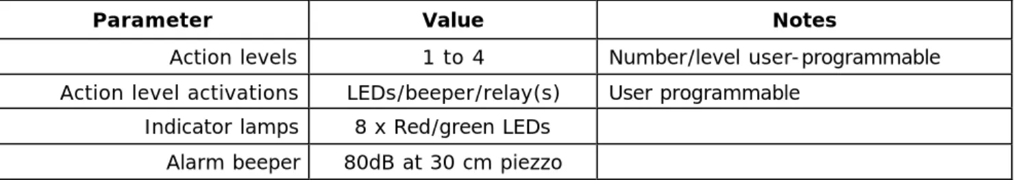
© 2002-2005 Neodym Technologies Inc. KnowzNet™ Datasheet – Page 5 TABLE 2.5 – Indicators and Activations
Parameter Value Notes
Action levels 1 to 4 Number/level user-programmable Action level activations LEDs/beeper/relay(s) User programmable
Indicator lamps 8 x Red/green LEDs Alarm beeper 80dB at 30 cm piezzo
TABLE 2.6 – Relay Specifications
Parameter Symbol Min Typ Max Unit
Master relay (SPDT) Switch voltage: Switch current: Carry current: Contact resistance: Insulation resistance: - - - - - - - - - - 220 2 3 0.05 108 VDC A A Ohm Ohm Optional zone relays (SPST)
Switch voltage: Switch current: Carry current: Contact resistance: Insulation resistance: - - - - - 200 0.5 1.2 0.15 101 0 - - - - - VDC A A Ohm Ohm TABLE 2.7 – AC Characteristics
Parameter Symbol Min Typ Max Unit
Warm-up time TW A R M U P - 60 - S
Fundamental operating frequency FO S C - 4 - MHz
COP watchdog time -out time TC O P - 32.8 - mS
ADC sampling rate TS A M P - 32.8 - mS
Signal averaging period TA V G - 500 - mS
Serial port baud rate - - 4800 - Bits/S
USB port speed - - 12 Mb/S
TABLE 2.8 – Environmental Parameters
Parameter Symbol Value Unit
Storage temperature tS T G -40 to +85 Deg. C.
Operating temperature range tO P 0 to +70 Deg. C.
© 2002-2005 Neodym Technologies Inc. KnowzNet™ Datasheet – Page 6
2.9 – OPERATING POWER
ABSOLUTE MAXIMUM RATINGSNote: Maximum ratings are the extreme limits to which the panel can be exposed without permanent damage. The panel is not guaranteed to operate properly at maximum ratings.
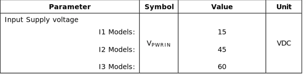
TABLE 2.9.1 - Absolute Maximum Ratings
Parameter Symbol Value Unit
Input Supply voltage
I1 Models: I2 Models: I3 Models: VPWRIN 15 45 60 VDC
INPUT SUPPLY VOLTAGE
Note: Permanent device damage may occur above the specified operating voltage range. Operating the panel below the required input supply voltage may lead to unstable operation, reduced sensor sensitivity, and/or sensor failure indications.
TABLE 2.9.2 – Operating Input Voltage Range
Parameter Symbol Value Unit
Operating voltage range
I1 Models: I2 Models: I3 Models: VPWRIN 12 to 14 12 to 40 12 to 60 VDC POWER CONSUMPTION
TABLE 2.9.3 – Supply current
Parameter Symbol Min Typ Max Unit
Supply current
I1 models: VPWRIN = 12VDC: I2/I3 models: VPWRIN = 24VDC: I3 models: VPWRIN = 48VDC: IPWRIN - - - 250 150 80 275 170 90 mA
© 2002-2005 Neodym Technologies Inc. KnowzNet™ Datasheet – Page 7
3 – ELECTRICAL INTERFACE
Figure 3.1 – Location of Panel Interface Connectors
LEGEND
A Back-up battery connector (Molex Mini-Fit Jr)
B Primary input power jacks (2.1 mm radial, center-negative) C Serial Port (DB-9)
D USB connector
E Zone relay terminal blocks (3.5mm) F Master relay terminal blocks (3.5mm) Figure 3.2 – Location of Panel Sensor Connectors
View from left View from right
Figure 3.3 – Sensor Connector Signals – Panel Side
SIGNAL TRM. BLK. “K1” RJ-11 “K2” HEADER “K3” PWR IN (12VDC) 4 5 4 SIG OUT (0-5VDC) 3 3 3 Ground (Common) 1 2 1
Figure 3.4 – Sensor Connector Signals – Sensor Head Side
SIGNAL TRM. BLK. “K1” RJ-11 “K2” HEADER “K3” PWR IN (12VDC) 1 2 1 SIG OUT (0-5VDC) 2 4 2 Ground (Common) 4 5 4
PLEASE NOTE: When terminating cables with RJ-11 plugs, the signals must cross over similarly to telephone cords.
A B C D E F 1 8 8 7 6 5 1 2 3 4 1 2 3 4 1 2 3 4 5 6 1 2 3 Top of Panel
Terminal Block RJ-11 Pin Header
1 2 3 4 1 2 3 4 5 6
Terminal Block RJ-11 Pin Header 4
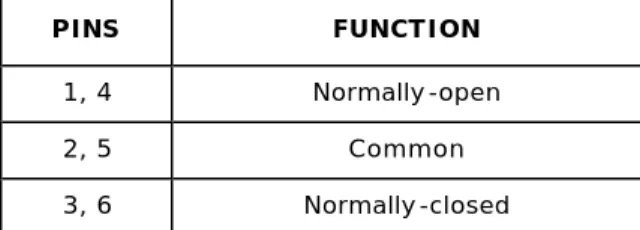
© 2002-2005 Neodym Technologies Inc. KnowzNet™ Datasheet – Page 8 Figure 3.5 – Master Relay Contacts
PINS FUNCTION
1, 4 Normally-open
2, 5 Common
3, 6 Normally-closed
Note: Contacts described in relay’s activated state
Figure 3.6 – Battery Connector Pins
PINS FUNCTION
1, 4 +12VDC Terminal (Positive) 2, 3 Ground Terminal (Negative) 1 2 3 4 Top of Panel 5 6 1 2 3 Top of Panel 4
© 2002-2005 Neodym Technologies Inc. KnowzNet™ Datasheet – Page 9
4 – PHYSICAL DIMENSIONS
FIGURE. 4.1 – Panel Dimensions
inches (mm) 4.40 (111.8) 8.50 (33.5) MATERIAL Anodized aluminum 0.040 (1.0) 4X 0.137 (3.5) 6.70 (26.4) 1.0 (25.4) 1.40 (35.6) 4.15 (105.4) 5.40 (137.2) 5.80 (147.3) 8.0 (203.2) 4.00 (10.2) 2.25 (57.1 ) 5.30 (134.6) 2X 0.156 (4.0) 2X 0.312 (7.9)
© 2002-2005 Neodym Technologies Inc. KnowzNet™ Datasheet – Page 10 FIGURE. 4.2 – Sensor Head Dimensions
TOP VIEW
0.150 (3.8)
+
LONG SIDE VIEW
SHORT SIDE VIEW
inches (mm) 0.350 (8.9) 1.250 (31.7) 1.450 (36.8) 1.600 (40.6) 0.040 (1.0) 1.125 (28.6) 0.250 (6.3) 1.050 (26.7) 1.250 (31.7) 1.500 (38.1) 0.250 (6.3) 1.125 (28.6) MATERIAL Anodized aluminum 0.040 (1.0) 0.800 (20.3) 0.160 (4.1) 4 x 0.405 (16.0) 0.570 (14.5) 0.125 (3.2)
© 2002-2005 Neodym Technologies Inc. KnowzNet™ Datasheet – Page 11 FIGURE. 4.3 – Sensor Head Connector Dimensions
inches (mm) 0.250 (6.3) 0.450 (11.4)
Terminal Block Version
0.250 (6.3) 0.312 (7.9) 0.250 (6.3) 0.447 (11.3)
RJ-11 & Hirose Version 1.150 (29.2) 1.075 (27.3) 0.525 (13.3) 0.050 (1.3) 0.285 (7.2) 0.138 (3.5) 0.625 (15.9) 1.085 (27.6) Terminal Block Version
Hirose Header Version
© 2002-2005 Neodym Technologies Inc. KnowzNet™ Datasheet – Page 12
5 – SALES & TECHNICAL SUPPORT
5.1 – PART NUMBERING
KN-Gxx-Axxx/yyy-Zn-In-Bn-Kn
Device ID KnowzNet™
Target gas Gxx – (Per sensor type)
Alarm level
Axxx(/yyy) where:
xxx is % of sensor range, yyy is low alarm (EG O2)
Zone
relays Z0 – None Z1 – Included
Input power I1 – 12VDC I2 – 12-to-40VDC I3 – 12-to-60VDC Back-up battery B0 – None B2 – 2-hours B4 – 4-hours B8 – 8 Hours
Connector K1 – RJ-11 (6-4) K2 – Terminal block 3.5mm K3 – Hirose DF3 2mm
© 2002-2005 Neodym Technologies Inc. KnowzNet™ Datasheet – Page 13
5.2 – CONTACT INFORMATION
CORPORATE OFFICE:
Neodym Technologies Inc. #711-675 West Hastings Street Vancouver, British Columbia Canada V6B 1N2
Toll-free: 1-877-723-5400 (North America)
TELEPHONE: International: +1-604-939-5544 FAX: +1-604-939-4153
INTERNET: Corporate website: www.neosafe.com www.neodymsystems.com
EMAIL: Sales: [email protected] Technical Support: [email protected]