Sharif University of Technology
Scientia IranicaTransactions D: Computer Science & Engineering and Electrical Engineering http://scientiairanica.sharif.edu
Multi-objective optimization design and performance
evaluation of slotted Halbach PMSM using Monte
Carlo method
I. Bouloukza
a, M. Mourad
a;, A. Medoued
a, and Y. Sou
b a. University of 20 aout 1955 Skikda, Department of Electrical Engineering, Skikda, Algeria. b. University of Tebessa, Department of Electrical Engineering, Tebessa, Algeria.Received 27 November 2015; received in revised form 2 October 2016; accepted 12 November 2016
KEYWORDS Permanent magnet machine;
Design methodology; Optimization; Monte Carlo method; Performance;
Finite-Element Analysis (FEA).
Abstract.This paper proposes the optimized design of Permanent Magnet Synchronous Motor (PMSM) based on the analysis of radial-ux permanent magnet motor with minimum weight, maximum eciency, and an increased torque. The rotor of the PMSM uses segmented permanent magnets mounted on the surface. The achievement of the method involves four steps. Firstly, the simplied motor model is presented in a manner which yields symbolic solution for optimal motor parameters as a function of mass. Secondly, Monte Carlo method is employed to compute optimal motor dimensions to obtain eciency, torque, and active mass of the optimal motor. Then, the steady-state characteristics of the primary optimized design obtained in the last step are calculated and compared to satisfy the ux condition. Finally, the performance of the optimized machine is calculated using 2D transient Finite-Element Analysis (FEA). Subsequently, the model mesh and boundary conditions are handled and presented. According to the obtained results, the essential purpose of the work has been fullled, the weight has been reduced by 24%, and the eciency and rated torque have been improved by 8% and 40%, respectively. The proposed design approach has the advantage in terms of its signicant time reduction of the design cycle.
© 2018 Sharif University of Technology. All rights reserved.
1. Introduction
Nowadays, the design of optimized electrical machines has several concerns. The choice of the design is adopted to reect various phenomena involved, and the denition of the optimization procedure is also adopted to determine the dimensions and materials to achieve the intended specications. Electrical machines' design is usually preceded by a pre-dimensioning in which one must meet the requirements of speed and exibility.
*. Corresponding author. Tel./Fax: +213 38723164
E-mail address: mordjaoui [email protected] (M. Mourad) doi: 10.24200/sci.2017.4361
The search for new modeling and optimization tools, in the design of electrical machines, is an ongoing concern of electrical engineering researchers. A design problem statement by the specications is generally turned into a mathematical optimization problem. Indeed, the coupling of a constrained optimization algorithm with an analytic model allows for exploring vast space solutions for convergence of the best conguration.
The resolution of an optimization problem in electric machines is often a very complicated task because many factors are involved. The optimization algorithms applied to the eld of Electrical Engineering have enjoyed great development. Indeed, they can solve problems, which have been previously intractable, and lead to innovative solutions. The optimization
of electrical machines is a nonlinear problem, since it is likely to generate multiple local optima, among which the optimum overall desired is obtained. All optimization methods can nd an optimum solution, but without any guarantee of what the global optimum in the single-objective optimization is. However, the complex part of any optimization method is how to locate the maximum and/or minimum of the opti-mized function which is a considerable challenge. The problem is how to choose a method adaptable to the problem. The optimization methods are numerous, we quote Monte Carlo [1], genetic algorithm [2], Particle Swarm Optimization (PSO) [3], etc.
Several research and investigations into PMSM design optimization are reported in the literature [4,5]. However, various analytical models using analytic eld solution have been proposed. Some of them concern rotational electrical machines [6-10], while others con-cern linear machines [11,12]. An attractive motor design method and its analysis is presented in [6]. It is shown that the Halbach magnetized PMSM motor has 15% lower volume than the radial magnetized one. We note that the important details of the design results are not presented in this paper. Sadeghi and Parsa [7] presented an optimization design study of ve-phase Halbach permanent-magnet machine in their work using genetic algorithm method to optimize the design variables based on the analytical model of the motor for high eciency, torque, and high acceleration. Mardaneh et al. [8] presented a modied analytical approach to the magnetic eld calculation in a slot-less two-rotor axial-ux permanent magnet machine. The analytic-modeling is based on the calculation of scalar and vector magnetic potentials, which are produced by the magnets and armature windings. The considered analytical model predicts the magnetic eld with small error compared to the nite-element method.
In electromagnetic design, several direct ap-proaches using scalar magnetic potential to solve the system governing equations, from which the ux lines' distribution can be achieved, are handled [13,14]. Other approaches and analytical calculations use mag-netic equivalent circuit [15,16]. Besides electromag-netic analysis, thermal study is another feature, which is generally implemented with lumped-parameter ther-mal networks [17,18].
Numerical methods are used to solve equations describing the behavior of electromagnetic machines in 2D and 3D with minimal assumptions which oer an opportunity to bring local coupling phenomena to researchers' attention. The interest of these numerical methods in a design scheme is evident, especially during the stages of validation and renement of the solution. The nite-element method is one of the most used numerical methods employed in simulation of permanent magnets machines by dierent ways. Thus,
it depends on the state of the analyzed system, which is steady state or transient operation [19]. The drawback of FEA analysis lies in the long time of simulation, which makes the study of design variation dicult [20]. Owing to its advantage by comprehending both optimization and sampling algorithms in which the whole objective function is explored, for its well-understood convergence properties [1] and its eciency of providing optimal design [21], the optimization algorithm of Monte Carlo as a prevailing means for the complex problem is chosen to ensure a better optimization design. In addition, the advantage of the method in physical systems is its tendency to be simple, exible, highly scalable, and eminently parallelizable as to reduce the computation time. It is also interesting because it calculates the performance of a sample and allows for a detailed statistical analysis, which is very hard to do by other methods. The idea in Monte Carlo technique is to reiterate the experiment many times to obtain many quantities of interest using the law of various analytical and statistical methods.
This paper presents the whole design of the PMSM. However, a preliminary design is carried out. Thus, Monte Carlo method is used to optimize the machine dimensions and the eld distributions based on an analytical model. Therefore, we consider char-acteristics of primary and optimized designs. Finally, the nite-element implementation is attempted for a computation of the transient electromagnetic eld of the optimized machine. During the processing stage, a 2D transient mode solver with a time-stepping approach is performed. The exact magnetic quantities inside the motor are calculated numerically.
The paper is organized as follows. Section 2 des-ignates the preliminary design of PMSM and magnetic ux analytical calculation. Section 3 describes the analytical optimization of torque. Section 4 provides and explains the Monte Carlo optimization approach and design results. Section 5 is dedicated to the results of obtained characteristics and comparisons with those obtained analytically. Section 6 presents the transient nite-element study of the optimized motor. Finally, Section 7 concludes the paper.
2. Preliminary design
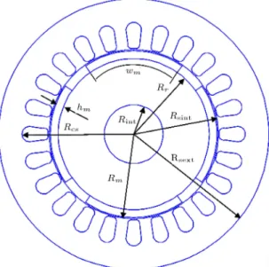
The motor cross-section used in the preliminary motor design is shown in Figure 1. It is comprised of twenty-four slots in the stator and the twenty-four-pole segmented Halbach permanent magnet material XG 196/96 in the rotor. The geometrical parameters considered are the stator diameter on air gap side D, the thickness of magnet, hm, and axial length, L, in Z-axis direction.
2.1. Assumptions
Figure 1. Denition of the geometrical parameters of the PMSM.
account during analytical solution for the ux lines dis-tribution produced in p poles pairs Halbach magnetized magnet machine:
The magnet is fully magnetized and oriented accord-ing to the Halbach magnetization direction;
All the ux produced by the permanent magnet is linked to a stator winding;
The motor has slotted stator structure;
Inner radius, r, and yoke thickness, , are zero in both models.
2.2. Air-gap ux density
The rst consideration in the optimization strategy is to nd the value of magnetic ux density, B, at the stator/air-gap interface. As mentioned later, B is solely a function of the motor geometry for a given remanent ux density; hence, the analytic model must be able to calculate B at the desired interface for a given set of geometric constraints (including r and d). The proposed method by Xia et al. [19] and Zhu and David Howe [22] will be extended to calculate magnetic eld of permanent magnet motors due to Halbach permanent magnet.
The analytical equations of the ux density at point (r, ) dened by the polar coordinates with the center of the rotor are given by:
Bmag(r; ) =K 4Br:p
0(1 + p)(1 + r)
" 1 Rr Rm p+1# r Rs
p 1 r
Rs p+1 + Rm r p+1
: cos(p:); (1)
where K0 is given by:
K0=2:
(
(1 r)
Rr
Rm
2p)
(1 r)
+ (1 + r)
Rm
Rs
2p
(1 r)
(1 + r)
+ (1 r)
Rm
Rs
2p
: (2)
p is the number of poles, n is the order in Fourier series of the ux density waveform, Rr, Rm, and Rsare
geometry parameters, and Bris the magnet remanence.
3. Analytical optimization
The analytical model analyzed in this paper was rst used and developed by Pinkham [23]. It uses expres-sions for air gap ux-density which is approximated as being independent of R, L, and p. Inner radius, r, and yoke thickness, , are zero in this model. The torque is approximately proportional to:
T _ (pBRL)2cR2=p
pL + R; (3) where ux-density amplitude, B, is independent of R, L, and p, and is given by:
B = Bremhm
g + hm: (4)
The partial derivative with respect to R simplies to: @T
@R =
pB2V2s pV R2 + R
2pV
R3 1
; (5)
and, therefore, R at maximum torque is:
R = (2pV )1=3; (6)
and it is easily shown that p at maximum torque is innite. This equation may be written as follows:
pL R =
1
2: (7)
We rst seek an approximate expression for the optimal R value in terms of p, V , and r. It will be veried that the expression derived for r is equal to zero, pL=R = 3=2 also holds when r is non-zero. With the stator volume as given above, the solution for R is:
R = h
122(9pV +p(9pV )2 122r6)i2=3+ 122r2
6h122(9pV +p(9pV )2 122r6)i1=3 (8):
The maximum torque is proportional to:
T _ V3=2: (9)
Therefore, the torque density increases by increasing radius only if P L > 1=2. Otherwise, the torque density increases by increasing axial length.
4. Monte Carlo optimization
Various optimization methods have been reported for use in the machine design. The Monte Carlo method plays an important role among these methods [1,21]. The mechanism of a Monte Carlo method is based on the idea of taking a simple random-drawn population and estimating the desired outputs from this sample. In summary, the Monte Carlo method involves essen-tially three steps:
Generating a random sample of the input parame-ters according to the (assumed) distributions of the inputs;
Analyzing (deterministically) each set of inputs in the sample;
Estimating the desired probabilistic outputs and the uncertainty in these outputs using the random sample.
The Monte Carlo method is exible and easy to implement and modify. However, there are some disadvantages to the method; for instance, for very complex problems, a large number of replications may be required to obtain precise results [20]. In this part, the Monte Carlo method is used to compute the optimal design parameters for given numerical values of material parameters.
4.1. Description of method
To use a Monte Carlo method, one must rst put in the form of a mathematical expectation the quantity that one seeks to compute. It is often simple (calculation of integral, for example), but perhaps more complicated (partial dierential equations, for example). At the end of this step, the amount of form E(X), i.e. the expectation of random variable X, is calculated.
To calculate E(X), we need to simulate a random variable according to the law of X. We then have sequence X(i)1iN, where N is the achievement of
random variable; X is then approximated (X) by the following equation:
E(X) N1(X1+ ::: + XN): (10)
4.2. Objective function
In this work, a multiple-objective optimization problem with multiple constraints has been used. The process of the method is described by Eqs. (11) to (14). The design variables are:
~x = [x1; x2; :::; xd] ; ~x 2 Rd: (11)
The constraints of the design are:
gj(~x) 0; j = 1; :::; m: (12)
The boundary of the design parameters is: xl
i xi xki; i = 1; :::; d; (13)
the objective function is:
f(~x) = [f1(~x); f2(~x); :::; fk(~x)] : (14)
The main goal of this study is the design of permanent-magnet machine with high eciency and low active weight. So, the design objectives are specied by the following function:
maximize F (x) = min[Zj(x)] ' = 1; 2; :::; N; (15)
where x 2 X (the feasible region) and Zj(x) is
calculated for optimal non-negative target value fj > 0
as follows:
Zj(x) = fjf fj
j ' = 1; 2; :::; N: (16)
The main objectives of the design are:
Minimize active mass that contributes to the cost of the motor;
Maximize eciency;
Maximize rated torque.
4.3. Design variables and constraints
The geometry parameters of the motor under study are to be obtained from the solution to an optimization problem, application of Monte Carlo method, and com-parison to those obtained analytically. The objective is to minimize weight and meet the requirements and constraints that guarantee certain required specica-tions. The owchart given by Figure 2 shows the diverse steps conducted during the optimization design procedure from the choice of initial variables to the calculation of eciency and weight. In the multi-objective optimization, the design variables are chosen to optimize all objective functions simultaneously while checking that the result is reasonable. If a particular design is not feasible, it is useless and a new iteration begins.
Five design parameters are randomly chosen from a specied range given in Table 1: pole number, p, inner radius, r, air gap radius, R, axial length, L, magnet height, hm. Tooth arc, = D:R=P , and eciency are
calculated during the simulation process. The Monte Carlo method is applied to optimize the variables with respect to the objectives function.
There are a number of constraints imposed on the design. Those constraints are:
Minimum eciency: 0:8;
Figure 2. Optimization of design owchart.
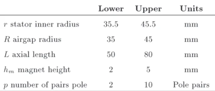
The design variables are the number of pole pairs, the machine length, and other geometrical parameters. The variables and ranges of their lower and upper bounds are specied in Table 1. The thickness of permanent magnets has been considered and limited to 5 mm to circumvent too high ux leakage among two adjacent permanent magnets.
Table 1. Variables used in the optimized design. Lower Upper Units r stator inner radius 35.5 45.5 mm
R airgap radius 35 45 mm
L axial length 50 80 mm
hm magnet height 2 5 mm
p number of pairs pole 2 10 Pole pairs
4.4. Optimization procedure
In this part, the optimal designs are determined by computing torque for random combinations of design parameters.
The corresponding objective functions are dened as follows:
Motor eciency is calculated by: =PPout
in =
T T +2
3(pT)2Ra
; (17)
where T and are the required output torque and speed, respectively, is the phase ux-linkage, and Ra is the phase winding resistance. The output
torque for given eciency and speed is:
where Bag is the air gap ux-density amplitude
given by Eq. (19), is the conductivity of copper, Awis the wire cross-sectional area given by Eq. (20),
and L is the wire length:
Bag= g + hBrehm m
1 e pRL
; (19)
Aw=R2 (r + R=p)2
2p(R r R=p)R=p: (20)
Motor active mass is given in grams by:
m = L
(R + hm+Rp )2 r2
: (21)
In the previous section, optimal design parameters have been studied by assuming that and V are constants. To be sure, however, is not a constant since it depends on p, R, and magnet height hm,
all of which we seek to optimize. Precise design optimization must, therefore, use both remanent ux-density Bre and saturation ux-density Bsat as
known constants instead of .
4.5. Flowchart of the optimization design The owchart revealed in Figure 2 illustrates the prevailing procedure of design optimization used in this research by which each component will be explained in the following. The execution of the code starts with the performance specications, such as the initial motor design variables. Each design parameter and penalty limits of penalty function can be varied within its domain. However, there are two stages in the proposed approach.
The rst stage is the calculation of design pa-rameter by the analytical model. As can be seen, eciency and weight, which are closely related to the dimensions and ux density distributions of the stator, are minimized by using an analytical model.
The second stage is the application of the Monte Carlo method to optimize the obtained analytical design by the following steps:
1. Dene the solution space. Select the parameters to be optimized. Here, the parameters are pole number, p, inner radius, r, air-gap radius, R, axial length, L, magnet height, hm, and tooth arc, ;
2. Dene a vector multi-objective function. In our case, the minimum weight and highest eciency are both the design objectives;
3. Initialize random locations and velocities;
4. Assume a design that meets the feasibility criteria; its weight and eciency are compared with a list of existing \good" designs that have been saved from
the previous iterations. The algorithm terminates after testing the specic convergence and optimum design achievement. At this point, the designer discusses the performance analysis of the proposed design. If the optimization is satised, then the design optimization process must be halted, and the new design is saved.
4.6. Optimization results
With respect to the owchart shown by Figure 2, the machine parameters obtained from the analysis are summarized in Table 2. The analytical results are given in Table 3.
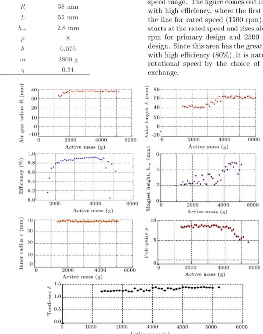
4.7. Comparison results
Multi-objective optimization is applied to three goals, i.e. eciency, torque, and mass. The optimized design parameters and predicted eciency are shown in Fig-ure 3 as functions of active mass. In this part, the Monte Carlo optimization results are compared with the analytic expressions derived in the last section. As shown in Figure 3, the air-gap radius increases as motor mass to the approximately 1500 (g). Eq. (7) predicts an increase to 1/2 for pole number. The Monte Carlo results show that pole number increase to 8 in an interval between 1500 g-4000 g; after this interval, the pole number decreases to have the mass of a primary machine. Eq. (8) was derived based on the assumption that Eq. (7) was valid, whereas the assumption applies only when the inner radius is zero. The results of Monte Carlo verify this hypothesis that Eq. (7) holds
Table 2. Primary design specications. Selected dimensional parameters Value
p pole pair 4
Rirotor inner radius. 13 mm
Rr rotor outer radius. 33.5 mm
Rsstator inner radius. 37.5 mm
Rmpermanent-magnet radius. 37 mm
ag airgap thickness 0.5 mm
Bremremanent ux density 0.96T
Bsatiron saturation level 1.9T
km magnet leakage factor 0.93
conductivity of XG196/96 6.9.105
hmmagnet radial height 3.5 mm
L axial length 65 mm
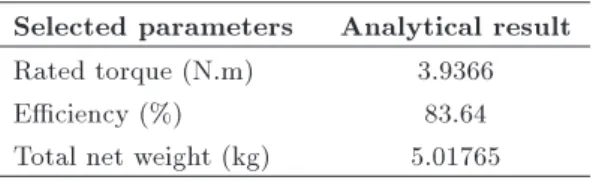
Table 3. Analytical results.
Selected parameters Analytical result Rated torque (N.m) 3.9366
Eciency (%) 83.64
approximately, but not exactly, when the inner radius is non-zero. However, due to the approximations described in the analytical optimization, a conrmation of these results is desirable. The optimization results are summarized in Table 4.
Due to the large number of iterations, designs are not truly optimal. Nevertheless, with an adequate number of iterations, the list can reach the near-optimum curve arbitrarily. It is noted that no points in Figure 3 represent the operating points that are practically continuous, in which the initial slope of the eciency versus mass curve is zero; moreover, the
Table 4. Optimum design variables specications. Quantity Value
r 38.5 mm
R 38 mm
L 55 mm
hm 2.8 mm
p 8
0.075
m 3800 g
0.91
eciency increases faster than the linear mass in the very low-eciency regime.
5. Optimization results discussions
It is interesting to consider the parameters chosen for the optimal values of mass and eciency (Figure 2), as discussed in advance due to quantization errors in the optimal calculation of machine parameters. The design, meeting the feasibility criteria, its eciency, torque, and power outputs, is compared with the two previous designs.
5.1. Eciency-speed characteristics
Figure 4 shows the eciency of the previous machine using the interpolation done in Matlab over the whole speed range. The gure comes out in two distinct areas with high eciency, where the rst starts as it follows the line for rated speed (1500 rpm). Then, the second starts at the rated speed and rises along the line of 2000 rpm for primary design and 2500 rpm for optimized design. Since this area has the greatest extent in power with high eciency (80%), it is natural to assume this rotational speed by the choice of conditions for the exchange.
Figure 4. Eciency versus speed curve.
Figure 5. Torque versus speed curve.
5.2. Torque-speed characteristics
The braking torque variation with the rotation speed for two topologies is calculated and plotted in Figure 5. Speed and torque are inversely proportional; speed decreases as torque increases. At the rated speed ( 1500 rpm), the value of torque in the optimized design is superior to that of the primary design.
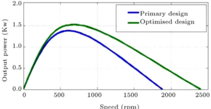
5.3. Power-speed characteristics
Power versus speed graph is also calculated for two previous designs. Figure 6 compares the power versus speed characteristics of two models. It can be seen that the machine with lower speed has the same performance in two designs. It is due to constant power regime (0-500 rpm), where the current is kept at its rated value, but in the ux-weakening regime over corner speed (500 rpm), the magnitude and position of the current vector must be adjusted.
Figure 6. Power versus speed curve.
6. Transient nite-element results
As a well-established design and modeling tool in electromagnetic design of electrical machines, 2D nite-element method is applied to the performance calcula-tions of the optimized machine. In order to reduce the computation time, the described geometry of the motor is reduced to cover only one pole with the help of boundary conditions and symmetry. The accuracy of the calculation results is related to the number of nodes, connected lines, and analysis meshes. However, the solution to this problem is obtained after three stages: pre-processing, processing, and post-processing stages. In pre-processing, motor geometry and compo-nent's material properties are dened, boundary condi-tions specied, mesh partition pinpointed, and motion parameters set. We must note that Maxwell software used in this work adopts adaptive meshing; for its design, it modies the gridding dimension by repeating iterations, and nally forms a rational meshing. During the processing stage, a transient mode solver with time-stepping is performed. Then, exact magnetic quantities inside the motor are calculated numerically. Finally, the magnetostatic solver is used to check the value of the torque developed for the particular current values. 6.1. Governing equation
The governing equation of segmented Halbach perma-nent magnetic machine is:
dA dt
1 0r
2A (rA)= r'+r M;
(22) where A is the axial component of magnetic vector potential, 0 is the permeability of the free space,
is the electrical conductivity, v is the velocity of the material, and M is the magnetization vector. ' is the electric scalar potential related to other eld variables by:
B = r A; (23)
E +dAdt = r'; (24) where B and E are magnetic ux density and electric eld intensity, respectively.
Considering two-dimensional analysis, if the ve-locity term is avoided, the problem will be reduced to a scalar form and the magnetic vector becomes a z-axis scalar Az:
dAz
dt
1 0r
2A z
= r' + r M: (25)
Eq. (25) stands for the basic governing equation of the problem that must be solved by means of nite-element method.
6.2. Boundary conditions
Before the processing stage, boundary conditions need to be imposed on the solution domain. The most im-portant boundary conditions in nite-element analysis are the Dirichlet, Neumann, and periodical boundary conditions. The Dirichlet boundary conditions are imposed on the surface of the stator and the shaft as mentioned in Figure 7:
Aj B= Aj A= 0: (26)
The Neumann boundary conditions are specied to
Figure 7. Boundary conditions on a rotary machine.
force ux lines to pass the boundary at exactly 90
angle: @A
@n = 0: (27)
The periodical boundary conditions are applied gener-ally in a case when the model is reduced to the one pole pitch. In this case, the relationship between the potential values at dierent positions is:
Aj H = Aj G: (28)
6.3. Results and comparison
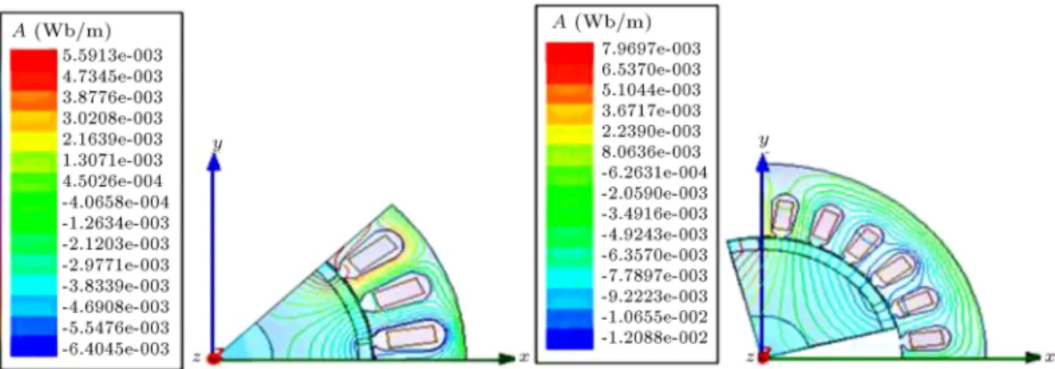
The software, called Maxwell, is used in the design calculation of the PMSM. Analytical design of the motor by the nite-element to calculate performances accurately is shown as the form of ux line, ux density, and meshes in Figures 8 to 10 for both preliminary and optimized design by Monte Carlo approach. The maximal values of the ux density for the magnet segments are 2.07 T and 1.63 T for preliminary and optimized designs, respectively.
The advantage of the FEA is the validity of the de-sign optimization that depends on the model accuracy. Therefore, the evaluation is conducted by a comparison of the result obtained by the analytical model and that obtained by transient FEM analysis. When the
Figure 8. The distribution of magnetic ux lines over machine cross section.
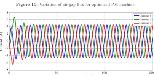
motor operates at transient time on two preliminary and optimized designs, the computed three-phase ux linkage waveforms are together computed by 2D model, which are shown in Figures 11 and 12 and represent the proles of the three-phase winding currents of the optimized design.
Figure 13 shows the torque versus times. Then, the present torque is compared to those of the two machines, i.e. the preliminary design with current of 1.54 A and the optimized design with current of 4.5 A. The estimated torques of preliminary and optimized designs are about 3.95 Nm and 6.37 Nm, respectively.
Figure 10. A view of the mesh for preliminary design.
From the input power, several power loss terms can be identied. The resultant stranded losses are shown in Figure 14. It is shown that the loss of the optimal machine is lower than that of the preliminary
Figure 13. Torque variation versus time of the preliminary and optimized PM machines.
Figure 14. Losses variation versus time of the preliminary and optimized PM machines.
Figure 11. Variation of air-gap ux for optimized PM machine.
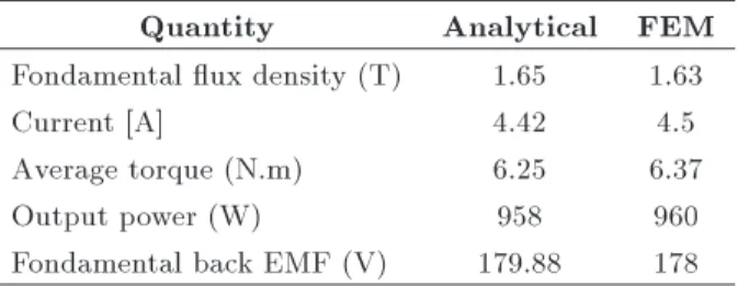
Table 5. Summary of the optimum design results.
Quantity Analytical FEM
Fondamental ux density (T) 1.65 1.63
Current [A] 4.42 4.5
Average torque (N.m) 6.25 6.37
Output power (W) 958 960
Fondamental back EMF (V) 179.88 178
design. Thus, the eciency is improved, especially in the high-speed region. In general, the optimal machine maintains high eciency in the entire procedure region when possessing an extended constant power speed range.
The corresponding FEM numerical results are given in Table 5, showing that a good agreement is realized between the nite-element calculations and the analytical calculated values of the optimum design. It is seen that the error is less than 6%, and it can be con-cluded that the analytical model is reasonably adequate to prove the eectiveness of the design optimization.
7. Conclusion
In this paper, we presented an optimized design for slot-ted Halbach PMSM. For high dynamic performance, analytical and Monte Carlo methods were compared. The Monte Carlo method was used to compute optimal values of the ve design parameters as a function of the mass for the given material parameter values. The obtained results were compared with those of analytical-derived optimum relationships. The design objectives concerning the structure optimization were achieved. As a conclusion, the optimized design oers a better performance regarding the improved eciency of 91% instead of 83%, smaller weight reduced by 24% and a rated torque of the machine as 8.7 N.m instead of 3.93 N.m of machine. The optimized machine was designed and the obtained results were validated throughout transient FEA using 2D model; so, the ux requirement determined in this study was satised.
References
1. Kroese, D.P., Taimre, T., and Botev, Z.I., Handbook of Monte Carlo Methods, 706, John Wiley & Sons (2013).
2. Ismail, M.S., Moghavvemi, M., and Mahlia, T.M.I. \Genetic algorithm based optimization on modeling and design of hybrid renewable energy systems", En-ergy Conversion and Management, 85, pp. 120-130 (2014).
3. Garca-Trivi~no, P., Llorens-Iborra, F., Garca-Vzquez, C.A., Gil-Mena, A.J., Fernandez-Ramrez, L.M., and Jurado, F. \Long-term optimization based on PSO of a grid-connected renewable energy/battery/hydrogen
hybrid system", International Journal of Hydrogen Energy, 39(21), pp. 10805-10816 (2014).
4. Caner, M., Gerada, C., Asher, G., and Ozer, T. \De-sign optimization of Halbach array permanent magnet motor to achieve sensorless performance using genetic algorithm", COMPEL-The International Journal for Computation and Mathematics in Electrical and Elec-tronic Engineering, 35(5), pp. 1741-1759 (2016).
5. Duan, R., Harley, G., and Habetler, T.G. \Multi-objective design optimization of surface mount per-manent magnet machine with particle swarm intelli-gence", IEEE Swarm Intelligence Symposium, pp. 1-5, St. Louis, MO,21-23 (September 2008).
6. Jang, S.M., Jeong, S.S., Wan Ryu, D. and Choi, S.K. \Design and analysis of high speed slotless PM machine with Halbach array", IEEE Trans. Magn., 37(4), pp. 2827-2830 (July 2001).
7. Sadeghi, S. and Parsa, L. \Multiobjective design optimization of ve-phase halbach array permanent-magnet machine", IEEE Transactions on Magnetics, 47(6), pp. 1658-1666 (June 2011).
8. Mardaneh, M., Mirsalim, M., and AliAhmadi, M. \A modied analytical approach in modelling and design of axial-ux permanent magnet machines", Amirkabir (Electrical Engineering), 17 (2006).
9. Davood, A.K. and Amir, N. \Design and simulation of PWM rectier connected a PM generator of micro turbine unit", Scientia Iranica D, 19(3), pp. 820-828 (2012).
10. Hashemi, Z., Mardaneh, M., and Sha Sadeghi, M. \High performance controller for interior permanent magnet synchronous motordrive using articial intelli-gence methods", Scientia Iranica D, 19(6), pp. 1788-1793 (2012).
11. Duan, Y., and Ionel, D.M. \A review of recent de-velopments in electrical machine design optimization methods with a permanent-magnet synchronous motor benchmark study", IEEE Transactions on Industry Applications, 49(3), pp. 1268-1275 (2013).
12. Wang, J., Howe, D. and Jewell, G.W. \Analysis and design optimization of an improved axially magnetized tubular permanent-magnet machine", IEEE Transac-tions on Energy Conversion, 19, pp. 289-295 (2004).
13. Markovic, M. and Perriard, Y. \Optimization design of a segmented Halbach permanent-magnet motor using an analytical model", IEEE Trans. Magn., 45(7), pp. 2955-2960 (July 2009).
14. Zhu, Z.Q., Wu, L.J., and Xia, Z.P. \An accurate sub-domain model for magnetic eld computation in slot-ted surface-mounslot-ted permanent-magnet machines", IEEE Trans. Magn., 46(4), pp. 1100-1115 (April 2010).
15. Cassimere, B.N., Sudho, S.D., and Sudho, D.H. \Analytical design model for surface-mounted perma-nent magnet synchronous machines", IEEE Trans. Energy Convers., 24(2), pp. 347-357 (June 2009).
16. Vaez-Zadeh, S. and Ghasemi, A.R. \Design optimiza-tion of permanent magnet synchronous motors for high torque capability and low magnet volume", Electr. Power Sys. Res., 74(2), pp. 307-313 (2005).
17. Makni, Z., Besbes, M., and Marchand, C. \Multi-physics design methodology of permanent-magnet syn-chronous motors", IEEE Trans. Veh. Technol., 56(4), pp. 1524-1530 (July 2007).
18. Legranger, J., Friedrich, G., Vivier, S. and Mipo, J.C. \Combination of nite-element and analytical models in the optimal multidomain design of machines: Application to an interior permanent-magnet starter generator", IEEE Trans. Ind. Appl., 46(1), pp. 232-239 (Jan./Feb. 2010).
19. Xia, Z.P., Zhu, Z.Q. and Howe, D. \Analytical mag-netic eld analysis of halbach magnetized permanent-magnet machines", IEEE Trans. Magn., 44(4), pp. 1864-1872 (Jul. 2004).
20. Stipetic, S., Zarko, D., and Kovacic, M. \Optimised design of permanent magnet assisted synchronous re-luctance motor series using combined analytical-nite element analysis based approach", IET Electric Power Applications, 10(5), pp. 330-338 (2016).
21. Senesky, M.K. \Electromagnetic generators for portable power applications", PHD Thesis University of California, Berkeley (2005).
22. Zhu, Z.Q., and Howe, D. \Instantaneous magnetic eld distribution in permanent magnet brushless DC mo-tors. IV. Magnetic eld on load", IEEE Transactions on Magnetics, 29(1), pp. 152-158 (1993).
23. Pinkham, A.P. \Modeling and optimization of per-manent magnet motors", Doctoral Dissertation, Mas-sachusetts Institute of Technology (2008).
Biographies
Ibtissam Bouloukza was born in Skikda, Algeria in 1983. She received engineer diploma with rst class honors in Electrical Engineering Option Electrical
Network in 2005. Also, she obtained magister degree in Option Electrical Machine in 2009 from the University of 20 aout 1955 of Skikda, Algeria. She is currently working for PhD degree. Her research interests are in design, modeling, and analysis of permanent magnet machine.
Mourad Mordjaoui is actually a Senior Lecturer in Electrical Engineering Department and a member in LRPCSI Laboratory, University of 20 aout 1955 of - Skikda. He has received PhD degree in Electrical Engineering at Batna University, Algeria. His research interests include electrical machines and drives, power systems, power electronics, articial intelligence ap-plied in electrical engineering, and optimization. He has published and co-authored more than 60 techni-cal papers in scientic journals and proceeding since 2006. He is a member of technical program commit-tee/international advisory board/international steering committee of many international conferences.
Ammar Medoued received the degree of Doctor of Sciences from University of Skikda, Algeria, in Electrical Engineering in 2012, LES laboratory. He is currently a Lecturer at the University of Skikda. His main research eld is electrical machine diagnosis. Youcef Sou received BEng (1991) and PhD degrees from the University of Annaba, Algeria in Electri-cal Engineering. Since 2000, he has been with the Department of Electrical Engineering, Laboratory of Electrical Engineering (Labget) at the University of Larbi Tebessi, Tebessa, Algeria, where he is currently an Associate Professor in Electrical Engineering. His main and current major research interests include electrical machines control, power electronics, and drives. He has published and co-authored more than 80 technical papers in scientic journals and conference proceedings since 2000. He is a member of editorial board in some journals and a member of technical program committee, international advisory board, in-ternational steering committee of many inin-ternational conferences.