11Mbps Wireless LAN Card
User’s Manual
Information in this document is subject to change without notice. No part of this document may be reproduced or transmitted in any form or by any means, electronic or mechanical, for any purpose, without the express written permission of the seller.
The seller provides this documentation without warranty, term, or condition of any kind. The seller may make improvements or changes in the product(s) and/or the program(s) described in this documentation at any time.
Other product and company names herein may be trademarks of their respective owners. 2002 All rights reserved.
Rev: 02 2002/08/27
Contents
Chapter 1 Introduction... 1
Wireless LAN Basics ... 2
Local Area Network (LAN)...2
Ad Hoc Network ...2
Infrastructure Network...3
Roaming...3
Chapter 2 Installing the Wireless LAN Card... 5
System Requirements... 6
Wireless LAN Card Status LEDs... 6
The Antenna on the Wireless LAN Card (Only for Wireless LAN USB Card)... 7
Contents II Monitor ...19 Statistics ...25 Site Survey...26 Encryption ...28 Advanced ...31 Version ...33 Saving/Loading Profile...34
PART 2. Configuration Utility for Windows XP ...35
Connecting to an Access Point or Wireless LAN Card...35
Viewing Wireless Connection Status ...37
Configuring Your Wireless Properties ...38
Chapter 4 Uninstalling the Wireless LAN Card ...45
Removing the Wireless LAN Card...45
Uninstalling the Wireless LAN Card Software ...46
Chapter 5 Updating the Device Driver ...51
Chapter 6 Troubleshooting...53
Radio Interference...53
Card Not Detected ...54
Cannot Connect to Another Wireless LAN Card...54
Poor Link Quality ...55
Contents
Appendix A Limited Warranty...57
Wireless LAN Hardware ...57
Wireless LAN Software ...58
Appendix B Regulatory Compliance ...59
FCC Part 15 Declaration of Conformity (DoC)...59
FCC Rules and Regulations - Part 15...60
FCC Radiation Exposure Statement...61
Appendix C Setting Up TCP/IP ...63
Appendix D Specification...67
Software ...67
Hardware ...69
Contents
IV
Table of Figures
Figure 3-1 Ad-Hoc Configuration... 21
Figure 3-3 Wireless LAN Monitor Utility – Statistics ... 25
Figure 3-4 Wireless LAN Monitor Utility – Site Survey ... 27
Figure 3-5 Wireless LAN Monitor Utility – Encryption... 29
Figure 3-6 Wireless LAN Monitor Utility – Advanced ... 32
Figure 3-7 Wireless LAN Monitor Utility – Version ... 33
Figure 3-8 Wireless LAN Monitor Utility – Saving Profile... 34
Figure 3-9 Windows XP Configuration Utility-Connect to Wireless Network ... 36
Figure 3-10 Windows XP- Connection Status ... 37
Figure 3-11 Windows XP Connection Properties -General... 39
Figure 3-12 Windows XP Connection Properties-Wireless Networks... 40
Figure 3-13 Windows XP-Add Preferred Networks... 41
Figure 3-14 Windows XP Configuration Utility-Set up Network to Aceess ... 43
Chapter 1 Introduction
This Wireless LAN Card is an IEEE 802.11b Wireless LAN PCMCIA/USB adapter. It allows your computer to connect to a wireless network and to share resources, such as files or printers without being bound to the network wires. Operating in 2.4GHz Direct Sequence Spread Spectrum (DSSS) radio transmission, the Wireless LAN Card transfers data at speeds up to 11Mbps. Both Ad-Hoc and Infrastructure mode are supported. For network security concern, 64/128-bit Wired Equivalent Protection (WEP) algorithm is used. In addition, its standard compliance ensures that it can communicate with any 802.11b networks.
This User’s Manual contains information on how to install and configure your Wireless LAN Card. Your Wireless LAN Card will allow you to connect your computer to other Wireless LAN Card equipped computers.
Chapter 1 Introduction
2
Wireless LAN Basics
This section conations some Wireless LAN basics to help you better understand how the product work together to create a wireless network.
Local Area Network (LAN)
Simply put, a LAN is a network that exists in a relatively limited area. A network is two or more computers connected together sharing files and peripheral devices such as printers. The Wireless LAN Card allows you to interact with other computers without having to run cables normally associated with networks. This lets you move your computer around while staying connected to your network.
There are two ways to use the Wireless LAN Card. One way is to connect directly to one or more Wireless LAN Card equipped computers, forming an Ad Hoc wireless network. The second way is to connect to an Access Point that gives you access to an existing wired LAN, forming an Infrastructure wireless network.
Ad Hoc Network
The Ad Hoc network offers peer to peer connections between workstations, allowing communication between computers within range that have an 802.11b DSSS compatible PC
Chapter 1 Introduction
card installed. A wireless Ad Hoc network can also access a wired LAN’s TCP/IP service (such as e-mail and the Internet) by using a TCP/IP software router on an Ethernet equipped PowerBook or notebook.
Infrastructure Network
The infrastructure network uses an access point (or several access points) as a gateway, linking the wireless network to a wired LAN. As a result, portable workstations or desktops on your wireless network have access to all of the features of your wired LAN including e-mail, Internet access, network printers and files server.
Roaming
Multiple Access Points can be installed to extend the wireless service coverage area for seamless wireless access. Within an extended service area, all Access Points and wireless clients must have the same Service Set Identity (SSID). Roaming among different Access Points is controlled automatically to maintain the wireless connectivity at all times.
Chapter 1 Introduction
Chapter 2 Installing the Wireless LAN Card
This chapter describes the system requirement and Wireless LAN Card status LEDs. In addition, we will guide you through the Wireless LAN Card installation as outlined below: For Windows 98(SE)/Me/2000/XP
1. Installing the software utility using the provided Software Utility CD.
2. Installing the hardware and then driver installation will be auto-processed.
Note: When connecting the hardware, note that this Wireless LAN Card is for use with UL listed I.T.E. computers.
After completing the steps listed above, if you need to set up the TCP/IP protocol to communicate with your network, refer to “Appendix C Setting Up TCP/IP” for details.
Chapter 2 - Installing the Wireless LAN Card
6
System Requirements
To use the Wireless LAN Card, your computer must meet the following minimum requirements:
n
Windows 98(SE)/Me/2000/XPn
32 MB of RAM, additional memory recommendedn
Standard PCMCIA slot/USB portWireless LAN Card Status LEDs
The two LEDs on the Wireless LAN Card indicate connection status and data transfer operation status, as described below:
LED Color State Description
Power Red On The adapter is plugged into the PCMCIA slot/USB port of
your computer.
Activity Green Blinking Transmission mode. The faster the LED blinks, the higher
Chapter 2 - Installing the Wireless LAN Card
The Antenna on the Wireless LAN Card (Only for Wireless LAN USB Card)
The USB adapter comes with one powerful antenna. You can rotate the antenna from 0 to 180 degrees to adjust its range and the connection quality.Note: Do not rotate the antenna more than 180 degrees, otherwise permanent damage may be caused.
Installation for Windows 98(SE)/Me/2000
Caution: Do not connect the Wireless LAN Card device to your computer before installing its
software. If this happens, the Windows PnP function will detect the PCMCIA/USB device
and issue a dialog box requesting its driver. Click Cancel to quit the wizard. Follow these steps to install the Wireless LAN Card software:
Chapter 2 - Installing the Wireless LAN Card
8
2.Insert the provided Software Utility CD into your CD-ROM drive and select
Utility&Driver. Or, run Setup.exe from the D:\Utility&Driver folder of the Software Utility CD where D is the drive letter. When the welcome screen pops up, click Next.
Chapter 2 - Installing the Wireless LAN Card
4. For quick installation, select Typical. For custom installation(to select the parameters that you would like to use), select Custom and click OK to go to next step.
5. Later, the following screen will pop up to ask you for plugging the wireless card onto the
PCMCIA slot/ USB port of your computer. Please do as the dialog request and click OK.
The red LED on the Wireless LAN Card will light when the Wireless LAN Card is connected to your computer.
Chapter 2 - Installing the Wireless LAN Card
10 Note:
1. If you are prompted with the INF not found alarm, please click the Browse button to
locate the INF file. Usually it is located on C:\Windows\INF or C:\Winnt\INF.
2. For Windows 2000: If you are prompted with the Digital Signature not Found alarm
message, just click Yes to ignore it and continue with the auto-installation.
3. For Windows 98(SE): If prompted, you need to insert your Windows 98(SE) installation
Chapter 2 - Installing the Wireless LAN Card
Note: If you need to set up the TCP/IP address or the subnet mask, refer to “Appendix C Setting Up TCP/IP” for details.
Now you are done with the installation procedure. Select Start > Programs >Wireless LAN Client Utility > Wireless LAN Monitor Utility. You should be able to see the Wireless LAN Monitor Utility icon appearing on the right side of the taskbar. Proceed to following chapter to configure or fine-tune your Wireless LAN Card settings.
Chapter 2 - Installing the Wireless LAN Card
12
Installation for Windows XP
Follow these steps to install the Wireless LAN Card software:
1. Close all Windows programs that are running.
2. Insert the provided Software Utility CD into your CD-ROM drive and select
Utility&Driver. For example, run Setup.exe from the D:\Utility&Driver folder of the
Software Utility CD where D is the drive letter. When the welcome screen pops up, click
Chapter 2 - Installing the Wireless LAN Card
3. License Agreement screen appears. Click Next.
4. For quick installation, select Typical. For custom installation (to select the parameters that you would like to use), select Custom and click OK to go to next step.
Chapter 2 - Installing the Wireless LAN Card
14
5. Later, the following screen will pop up to ask you for plugging the wireless card onto the
PCMCIA Slot / USB port of your computer. Please do as the dialog request and click OK.
6. Upon hardware detection, Windows OS will pop up a dialog as below. Please choose the
Chapter 2 - Installing the Wireless LAN Card
7. The Windows will copy the drivers form the Software Utility CD.
Chapter 2 - Installing the Wireless LAN Card
16 Note:
If you are prompted with the INF not found alarm, please click the Browse button to locate the INF file. Usually it is located on C:\Windows\INF or C:\Winnt\INF.
Chapter 3 Wireless LAN Monitor Utility
PART I. Wireless LAN Monitor Utility for Windows 98\98SE\Me\2000
Wireless LAN Monitor Icon
The Wireless LAN Card uses the Wireless LAN
Monitor Utility for both configuration and monitoring.
The utility is launched automatically with its icon located on the system tray. Right-clicking the icon displays the context menu.
If the utility is not launched, manually start the monitor by selecting Start > Programs >Wireless LAN Client Utility > Wireless LAN Monitor Utility.
Chapter 3 Wireless LAN Monitor Utility
18 The Wireless LAN Monitor icon color is green or yellow to indicate your Wireless LAN Card is in Infrastructure or Ad-Hoc mode respectively.
In Infrastructure mode, if the icon is marked with a red “X”, it means that the Wireless LAN Card is not connected to an Access Point. The following graphics show examples of
established and failed wireless connection in Infrastructure mode:
In Ad-Hoc mode, the icon is always like the following graphic, except when the card is resetting and initializing where it is marked with a red “X”.
Wireless connection is established .
Disconnected wireless connection.
Chapter 3 Wireless LAN Monitor Utility
Wireless LAN Monitor Utility
To start the utility program, double-click the icon or select About … from its context menu. The Wireless LAN Monitor Utility screen pops up with six tabs: Monitor, Statistics, Site Survey, Encryption, Advanced and Version. Please see the appropriate section which describes each tab item.
Monitor
Monitor function allows you to re-configure the Wireless LAN Card setting. Even though you have configured the settings during driver and utility installation, it is possible that you want to change your operating mode between Infrastructure or Ad-Hoc mode and fine-tune other settings.
You can connect your computer to a network in one of the following two ways. Refer to sequential sections for configuration:
Chapter 3 Wireless LAN Monitor Utility
20 Connecting to Other Wireless LAN Cards (Ad-Hoc Mode)
1. In the taskbar, double-click the Wireless LAN Monitor icon to display the Wireless
LAN Monitor Utility dialog box.
2. Click the Monitor tab.
3. In the Network Type list, select Ad-Hoc.
4. In the Channel list, select the Channel number that you want to use.
5. In the SSID list, type the Service Set ID (SSID) of the Wireless LAN group. All wireless
clients must use the same SSID in order to communicate with each other.
6. Click Submit.
7. Click Hide if you wish to exit the utility.
Chapter 3 Wireless LAN Monitor Utility
2. Click the Monitor tab.
6. Click Submit. 3. Select Ad-Hoc mode. 4. Select the Channel number. 5. Type the SSID name of the
Wireless LAN group. 1. Open Wireless LAN Cards
Chapter 3 Wireless LAN Monitor Utility
22 Connecting to Access Points (Infrastructure Mode)
1. In the taskbar, double-click the Wireless LAN Monitor icon to display the Wireless
LAN Monitor Utility dialog box.
2. Click the Monitor tab.
3. In the Network Type list, select Infrastructure.
4. In the SSID list, type Service Set ID (SSID) of the Access Point. The wireless client
must use the same SSID as the Access Point in order to communicate with other computers via the Access Point.
5. Click Submit. If the connection is successful, you should be able to find your computer
on the Network Neighborhood in Windows Explorer. 6. Click Hide if you wish to exit the utility.
Chapter 3 Wireless LAN Monitor Utility
2. Click the Monitor tab.
5. Click Submit.
3. Select Infrastucture mode. 4. Type the SSID name of the
Wireless LAN group. 1. Open Wireless LAN Cards
Chapter 3 Wireless LAN Monitor Utility
24 Checking Link Quality (Infrastructure Mode Only)
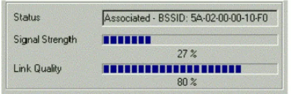
To check the link quality of the connection when in Infrastructure mode, double- click the Wireless LAN Monitor icon on the taskbar to display the Wireless LAN CMonitor Utility dialog box. Then click the Monitor tab. The connection status is shown at the bottom of the dialog box.
Status: Indicates the Access Point your Wireless LAN Card associated with. If no Access Point is connected, current status, such as scanning, authenticating, is displayed.
Signal Strength: Displayed as percentages using active progress indicators that change as the network radio signal fluctuates.
Link Quality: Link Quality categories are defined as follows: Link Quality Range(%)
Poor 0-29
Fair 30-59
Good 60-89
Excellent 90-100
Figure 3- 3 Infrastructure Mode Link Status
If you are in Ad- Hoc mode, the Signal Strength and Link Quality fields are grayed- out.
Chapter 3 Wireless LAN Monitor Utility
Statistics
Statistics feature allows you to view the available statistic information (Data packets). Tx indicates data is being transmitted whereas Rx indicates data is being received. To renew the statistics, click the Clear button.
Chapter 3 Wireless LAN Monitor Utility
26
Site Survey
Site Survey function scans the wireless network searching for available Access Points and wireless stations (Ad-hoc mode) within the range of the card. Available stations are listed with the following information:
BSSID: Basic Service Set ID. It is actually the MAC address of the Access Point/wireless station (Ad-hoc mode). It can be used to identify the stations when they have the same SSID. SSID: Service Set ID. Displays the current SSID of the Access Point/wireless station (Ad-hoc mode).
Signal: Shows the signal strength ratio. The higher the ration, the more powerful the signal received by your Wireless LAN Card. It helps you identify the quality network operation. Ch (Channel): The operating radio channel number.
WEP: Displays if encryption is enabled or disabled on the Access Point/wireless station
(Ad-hoc mode).
Type: Indicates whether the operating mode is Infrastructure (Access Point) or Ad-Hoc (wireless station).
Chapter 3 Wireless LAN Monitor Utility
Connecting to Desired Site by Site Survey Utility
If you want to connect to any of the Access Point(s) and Ad-Hoc Station(s) listed, double-click on your choice (on the BSSID field). The utility will take you back to the Monitor screen showing the parameters of the connection newly established.
Chapter 3 Wireless LAN Monitor Utility
28
Encryption
Encryption technology is used to enhance wireless media security. Your encryption settings must match those used by the Access Points or wireless stations (Ad-hoc mode) in your network, or your computer will be unable to communicate with others through network. If you are not going to use encryption, got to Encryption tab and select Disabled from the Encryption drop-down menu. Yet, if you want to enable encryption, please do the following:
1. Select the Encryption tab from the Wireless LAN Monitor Utility.
2. Select 64 Bit or 128 Bit asyour encryption type.
3. For flexibility, you can enter the WEP keys in either HEX or ASCII format. Enable the
preferred format and then enter the key values in the Key #1-4 fields.
If using HEX format, the utility converts two entered characters into its corresponding
ASCII code and vice versa. Note that when using HEX format, only digits 0-9 and letters
A-F are allowed. Valid key length for each encryption type is as below:
HEX Format ASCII Format
64 Bit 10 hexadecimal digits 5 ASCII characters
128 Bit 26 hexadecimal digits 13 ASCII characters
Note that the four keys, including the one selected as WEB Key to use, are used to decrypt the data you receive.
Chapter 3 Wireless LAN Monitor Utility
4. In the WEB Key to use box, select one of the four keys to encrypt the data you are going
to transmit.
5. Select Open System, Shared Key and Auto asthe Authentication Type.
Your authentication type must be the same as those on the Access Point/wireless client (Ad-Hoc mode) with which you want to associate.
6. To have the new settings take effect, click the Submit. Then click Hide to exit the utility.
Chapter 3 Wireless LAN Monitor Utility
Chapter 3 Wireless LAN Monitor Utility
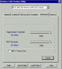
Advanced
Advancedfeature allows you to change advanced configuration settings: Fragmentation Threshold, RTS Threshold and 802.11 Power Save.
FragmentationThreshold: The fragmentation threshold, which is specified in bytes, determines whether packets will be fragmented and at what size. On an 802.11 wireless LAN, packets exceed the fragmentation threshold are fragmented, i.e., split into, smaller units suitable for the circuit size. Packets smaller than the specified fragmentation threshold value are not fragmented.
RTS Threshold: When set (in bytes), it specifies the packet size beyond which the Wireless LAN Card invokes its RTS/CTS mechanism. Packets that exceed the specified RTS threshold trigger the RTS/CTS mechanism. The NIC transmits smaller packets without using RTS/CTS. 802.11 Power Save: For uninterrupted data communication, you may leave this option blank to disable power saving feature. To enable power saving feature for your Wireless LAN Card, please check this box.
Chapter 3 Wireless LAN Monitor Utility
32 the slide bar and then use the right and left arrow keys of your keyboard to select an exact number.
Chapter 3 Wireless LAN Monitor Utility
Version
Version tab displays the basic information about the device, including the Driver, Firmware and Application Version. Use the Hide button if you wish to exit the application.
Chapter 3 Wireless LAN Monitor Utility
34
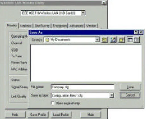
Saving/Loading Profile
The Wireless LAN Monitor Utility comes with Save Profile/Load Profile buttons at the
bottom of the panel. The profile feature allows you to save the current wireless networking settings, including the operating mode, channel, SSID, encryption and fragmentation/RTS threshold, to your computer. You can save multiple profiles for different network environment and easily retrieve the required one as needed.
To save the current configuration, please click Save Profile, then select a preferred location on your computer and save it with an easy-to-identify name (*.cfg). To restore the required configuration, just click Load Profile to locate the preferred profile.
Chapter 3 Wireless LAN Monitor Utility
PART 2. Configuration Utility for Windows XP
Under Windows XP, the Wireless LAN Card uses the Wireless Network Connection utility
for both configuration and monitoring. The utility can be quickly accessed via the network connection icon on the system tray. If your computer is not connected to any Access Point/Wireless LAN Card yet, the icon should appear as below:
Connecting to an Access Point or Wireless LAN Card
To connect to an existing Access Point/Wireless LAN Card (Ad-Hoc mode), do the following:
Chapter 3 Wireless LAN Monitor Utility
36 Figure 3-9 Windows XP Configuration Utility-Connect to Wireless Network
3. If the target Access Point/Wireless LAN Card (Ad-Hoc mode) has been set with WEP
key, you must enter the same WEP key in the Network key field. Otherwise, leave it
blank.
4. Click Connect, then you will join the target network and this dialog window will
disappear. When your wireless connection is established, the connection icon appears as below:
Chapter 3 Wireless LAN Monitor Utility
Note: If the wireless connection can’t be established, double-click the connection icon and then click Properties. Go to Authentication tab first to make sure that you use the correct authentication type for the Wireless LAN Card. For more information, refer to
“Authentication” on page 43.
Viewing Wireless Connection Status
After you successfully connect to the Access Point or Wireless LAN Card (Ad-Hoc mode),
double-click the icon in the system tray again. This will open the Wireless Network
Connection Status window where you can see the general data of the Wireless LAN Card, such as Status, Duration, Speed, Signal Strength, etc.
Chapter 3 Wireless LAN Monitor Utility
38
Configuring Your Wireless Properties
To configure your wireless properties, open the Wireless Network Connection Status
window as described above, and then click the Properties button. This will open the Wireless
Network Connection Properties window which allows you to configure more detailed items of the Wireless LAN Card. The following describes each tab of the properties window to help you do more settings of the Wireless LAN Card.
Chapter 3 Wireless LAN Monitor Utility
General
This tab allows you to specify the network methods to be used with your Wireless LAN PCMCIA/USB Card. The network policy depends on your wireless network. For TCP/IP protocol, you should configure its properties as instructed by your network administrator. For more information on TCP/IP setting, please refer to “Appendix C Setting Up TCP/IP” on page 63.
Chapter 3 Wireless LAN Monitor Utility
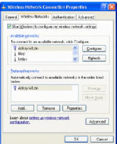
40 Wireless Networks
This tab contains two sections: Available networks and Preferred networks described as
below.
Under Available networks section, you can also see all the Access Points and Wireless LAN
Cards (Ad-Hoc mode) available in the air. Clicking Refresh will update the list of Access
Points and Wireless LAN Cards (Ad-Hoc mode).
Chapter 3 Wireless LAN Monitor Utility
Under Preferred networks section, you can add any wireless networks that you wish to
connect to. To do this, just click Add to add more Access Points or Wireless LAN Cards
(Ad-Hoc mode) to the list.
After you click the Add button, the Wireless Network Properties window pops up. Type
your network name (SSID) and, if needed, the wireless network WEP settings. Once the Access Point or Wireless LAN Card (Ad-Hoc mode) that you want to connect to has been set with WEP key, you must type the same WEP key as the Access Point’s or Wireless LAN Card’s.
Chapter 3 Wireless LAN Monitor Utility
42
After you add several profiles into Preferred networks, you can change the order in which
connection attempts to preferred networks are made. Just select the target wireless network and click Move up or Move down to move it to a desired position.
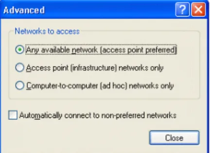
To Access Certain Wireless Network Only
If you just want to access certain wireless network type, click the Advanced buttonon the
Wireless Networks tab (Figure 3-12) to open the Advanced window. You can choose to
connect to the following networks:
•
Any available network ( access point preferred)•
Access point (infrastructure)•
Computer-to-computer (ad hoc)The default network type is Any available network ( access point preferred). In this
network type, your device will connect to any Access Points or Wireless LAN Cards (Ad-Hoc mode) available in the air but Access Point always demands higher connection attempt priority.
Once you finish the advanced setting, your wireless station will then connect to your desired
Chapter 3 Wireless LAN Monitor Utility
Figure 3-14 Windows XP Configuration Utility-Set up Network to Aceess Authentication
This tab allows you to configure the authentication settings of your Wireless LAN Card. The
most important setting for the Wireless LAN Card is to disable Enable network access
control using IEEE802.1X to ensure successful connection between the Wireless LAN Cards and Access Points or other Wireless LAN Card (Ad-Hoc mode). You must disable this
function for any reason. Otherwise, there may be some problems happening during connection. For other settings, we recommend you keep the default settings to minimize the problems
Chapter 3 Wireless LAN Monitor Utility
44 Figure 3-15 Windows XP Connection Properties -Authentication
Make sure to clear the Enable network access control using IEEE802.1X check box to ensure successful connection.
Chapter 4 Uninstalling the Wireless LAN Card
Should you need to uninstall the Wireless LAN Card and application software for any reason,, you should remove the hardware from your computer and then uninstall the associated software. Please proceed as follows.
Removing the Wireless LAN Card
The Wireless LAN Card complies with the PCMCIA/USB standard that allows devices to be
inserted into and removed from the computer’s PCMCIA slot/USB port when the computer is
power on. For USB Wireless LAN Card, just remove the card from your PC’s USB port. For
PCMCIA device, it is recommended that you follow the standard Windows procedure for disconnecting a PCMCIA device from your computer.
Chapter 4 Uninstalling the Wireless LAN Card
46 Note: To avoid any damage occurred for your computer, u nder Windows 98/ME operating
system, please click on the Wireless LAN Monitor Utility icon first before removing the
wireless LAN card. Press the right mouse button and select Exit. Later the icon will disappear. Then remove the wireless LAN card.
Uninstalling the Wireless LAN Card Software
Make sure that you have removed the hardware before you proceed.
1. Close all programs that are currently running.
2. Click the Windows Start button, point to Programs, Wireless LAN Client and then
Chapter 4 Uninstalling the Wireless LAN Card
48
3. Click OK to proceed with the software removal procedure.
Chapter 5 Updating the Device Driver
Periodically, you may need to upgrade the Wireless LAN Card’s driver when a newer version is available. Check our website for information about the latest driver upgrades. When you have finished the download procedure, please follow as below to update the device driver.
1. Uninstall the Wireless LAN Card as described in Chapter 4. Follow the steps to remove
the Wireless LAN Card and then uninstall the software.
2. Install the new driver you have downloaded. Refer to Chapter 2 for detailed instructions.
Chapter 6 Troubleshooting
Radio Interference
You may be able to eliminate any interference by trying the following:
•
Reseat the Wireless LAN Card.•
Increase the distance between the wireless computers and the device causing the radiointerference.
•
Plug the computer equipped with the Wireless LAN Card into an outlet on a differentbranch circuit from that used by the affecting device.
•
Consult the dealer or an experienced radio technician for help.Chapter 6 Troubleshooting
54
Card Not Detected
If the Wireless LAN Card is not detected by Windows, try the following:
•
Make sure the Wireless LAN Card is properly inserted in the PCMCIA slot/USB port.•
Make sure the PCMCIA slot/USB port in your computer is working.•
Contact your dealer for additional testing if there is a hardware problem with theWireless LAN Card.
Cannot Connect to Another Wireless LAN Card
If you cannot make a connection to another Wireless LAN Card from your computer, it could be due to one of the following reasons:
•
Incorrect SSID. Make sure the SSID is the same for all computers that have a WirelessLAN Card.
•
Changes are not being recognized by your computer. Restart your computer.•
If in Ad Hoc mode, make sure the Log on to Windows NT domain check box is notselected in the Client for Microsoft Networks Properties dialog box in the Network
Configuration tab.
•
Incorrect IP Address or Subnet Mask. Check these settings in the TCP/IP PropertiesChapter 6 Troubleshooting
Poor Link Quality
If the Link Quality display stays in the Poor range, it could be due to one of the following reasons:
•
Radio interference.•
Distance between Wireless LAN Card and Access Point is too far. Decrease thedistance between the Wireless LAN Card and Access Point (or another card).
Cannot Connect to Access Point
If you cannot make a connection to the Access Point, it could be due to one of the following reasons:
•
Make sure the Wireless LAN Card and Access Point have no physical connectionproblems.
•
Make sure the SSID for the Wireless LAN Card is the same as the Access Point.Appendix A Limited Warranty
Wireless LAN Hardware
The seller warrants to the end user (“Customer”) that this hardware product will be free from defects in workmanship and materials, under normal use and service, for 1 year from the date of purchase from the seller or its authorized reseller. The seller’s sole obligation under this express warranty shall be, at the seller’s option and expense, to repair the defective product or part, deliver to Customer an equivalent product or part to replace the defective item, or if neither of the two foregoing options is reasonably available, The seller may, in its sole discretion, refund to the Customer the purchase price paid for the defective product. All products that are replaced will become the property of the seller. Replacement products may be new or reconditioned.
Chapter 6 Troubleshooting
58
Wireless LAN Software
The seller warrants to Customer that each software program licensed from it , except as noted below, will perform in substantial conformance to its program specifications, for a period of 1 year from the date of purchase from the seller or its authorized reseller. The seller warrants the media containing software against failure during the warranty period. No updates are provided. The seller’s sole obligation under this express warranty shall be, at the seller’s option and expense, to refund the purchase price paid by Customer for any defective software product, or to replace any defective media with software which substantially conforms to applicable seller published specifications. Customer assumes responsibility for the selection of the appropriate application programs and associated reference materials. The seller makes no warranty or representation that its software products will meet Customer’s requirements or work in combination with any hardware or software applications products provided by third parties, that the operation of the software products will be uninterrupted or error free, or that all defects in the software products will be corrected. For any third party products listed in the seller software product documentation or specifications as being compatible, the seller will make reasonable efforts to provide compatibility, except where the non-compatibility is caused by a defect in the third party’s product or from use of the software product not in accordance with the seller’s published specifications or user manual.
Appendix B Regulatory Compliance
FCC Part 15 Declaration of Conformity (DoC)
The following equipment:
Product Name: Wireless LAN Card
is herewith confirmed to comply with the requirements of FCC Part 15 rules. The operation is subject to the following two conditions:
1. This device may not cause harmful interference, and
Appendix B Regulatory Compliance
60
FCC Rules and Regulations - Part 15
Warning: This device has been tested and found to comply with the limits for a Class B digital device pursuant to Part 15 of the Federal Communications Commissions Rules and Regulation. These limits are designed to provide reasonable protection against harmful interference when the equipment is operated in a commercial environment. This equipment generates, uses, and can radiate radio frequency energy and, if not installed and used in accordance with the instruction manual, may cause harmful interference to radio communications.
However, there is no guarantee that interference will not occur in a particular installation. If this equipment does cause harmful interference to radio or television reception, which can be determined by turning the equipment off and on, the user is encouraged to try and correct the interference by one or more of the following measures:
•
Relocate your WLAN equipped laptop computer.•
Increase the separation between the WLAN equipped laptop computer and other electronics.•
Connect the WLAN equipped laptop computer into an outlet on a circuit different from that ofother electronics.
Appendix B Regulatory Compliance
FCC Radiation Exposure Statement
This equipment complies with FCC radiation exposure limits set forth for an uncontrolled environment. This equipment should be installed and operated with minimum distance of 20cm between the radiator & your body.
Appendix C Setting Up TCP/IP
This section contains instructions for configuring the TCP/IP protocol of the Wireless LAN PCMCIA/USB Card. The IP address policy depends on your wireless network. You should configure your TCP/IP protocol as instructed by your network administrator.
1. On the taskbar, select Start > Settings > Control Panel, double-click the Network icon.
2. Click the Configuration tab of the Network dialog box.
3. In thenetwork componentslist, select the TCP/IP protocol of your Wireless LAN Card,
Appendix C Setting Up TCP/IP
64
4. On the IP Address tab, choose one of the methods as required:
Option A: Click Specify an IP address.
In the IP Address box, enter a valid four-component IP address, either a public or private one as required. If private IP address is used, the following three blocks of IP addresses are available for private networks:
10. 0 . 0. 0 — 10.255.255.255 172. 16. 0. 0 — 172. 31.255.255 192.168. 0. 0 — 192.168.255.255
In the Subnet Mask box, enter a valid four-component IP address.
For correct IP address information for your wireless LAN installation, contact your network administrator.
For more information on IP addresses, see the Network Working Group
Specification RFC 1918 on the Internet.
Appendix C Setting Up TCP/IP
Option B: Select Obtain an IP address automatically.
An IP address will be automatically assigned to your computer.
5. Click OK to return to Network dialog box and click OK again to finish configuration. If your TCP/IP properties have been modified, you will be prompted to restart your computer. Click Yes to have new settings take effect.
Appendix D Specification
* Specifications are subject to change with notice.
Software
Standards Compliance
•
IEEE 802.11 / 802.11b Standard
•
PCMCIA v2.1 Standard (WLAN PCMCIA Card)
•
USB 1.1 Compliant (WLAN USB Card)
Operation Modes
•
Ad-hoc mode
•
Infrastructure mode
Appendix D Specification
68 Monitor and
Configuration
•
Reliable and robust monitor and configuration utilities
•
Dynamic configuration
•
Network traffic statistics gathering
•
Clear LED Indicators for real time monitor current network
status
Device Driver and Configuration Utility
•
A PCMCIA NDIS 5.0 mini-port driver running on Windows
98(SE)/ME/2000/XP platforms(WLAN PCMCIA Card)
•
A USB NDIS 5.0 mini-port driver running on Windows
98(SE)/ME/2000/XP platforms(WLAN USB Card)
•
A monitor and configuration utility running on Windows
98(SE)/ME/2000 platforms
PS: Under Windows XP, use XP built-in monitor and configuration utility.
Appendix D Specification
Hardware
Interface
•
One 2.4GHz RF interface for Wireless LAN connection•
WLAN PCMCIA Card: One PCMCIA interface•
WLAN USB Card: One USB connectorRadio Characteristics
•
Frequency Band: 2.400 ~ 2.4835 GHz ISM Band (subject to local regulations)•
Spreading: Direct Sequence Spread Spectrum•
ModulationØ CCK: 11Mbps and 5.5Mbps
Ø DQPSK: 2Mbps
Ø DBPSK: 1Mbps
•
Number of ChannelsØ 11 Channels (US, Canada)
Ø 13 Channels (Europe)
Ø 14 Channels (Japan)
Appendix D Specification
70 Radio Characteristics
•
Antenna:Two Internal Antennas (WLAN PCMCIA Card) One external antenna (WLAN USB Card)
•
Transmit Power:17dBm (typical) (WLAN PCMCIA Card) 17dBm (typical) (WLAN USB Card (R)) 12dBm (typical) (WLAN USB Card (I))
•
Receiver Sensitivity:-80dBm @ FER < 8% (WLAN PCMCIA Card) -80dBm @ FER < 8% (WLAN USB Card (R)) -80dBm @ FER < 8% (WLAN USB Card (I))
Appendix D Specification
Power Requirement and Operation Environment Requirement
•
TemperatureWLAN PCMCIA Card
Ø Operating Temperature: 0°C to 55°C (32°F to 131°F)
Ø Storage Temperature: -10°C to 65°C WLAN USB Card (R)
Ø Operating Temperature: 0°C to 55°C (32°F to 131°F)
Ø Storage Temperature: -10°C to 80°C WLAN USB Card (I)
Ø Operating Temperature: 0°C to 55°C (32°F to 131°F)
Ø Storage Temperature: -20°C to 80°C
•
Humidity:5% to 80% (non-condensing) (WLAN PCMCIA Card) 5% to 80% (non-condensing) (WLAN USB Card (R)) 5% to 95% (non-condensing) (WLAN USB Card (I))
Appendix D Specification
72
WLAN USB Card (R) Ø Receive mode: 250mA
Ø Transmit mode:420 mA
Ø Doze mode: TBD
WLAN USB Card (I) Ø Receive mode: 322mA
Ø Transmit mode:382 mA
Ø Standby mode: TBD
Ø Sleep mode: TBD
LED Indicators (from left to right in front panel)
•
Activity (Green)•
Power (Red)PCMCIA Specification -WLAN PCMCIA Card
•
PCMCIA v2.1 Standard•
Plug and PlayAppendix D Specification
USB Specification -WLAN USB Card
•
USB 1.1 Compliant•
USB Slave•
Plug and Play•
Hot SwappingPhysical
-WLAN PCMCIA Card
•
Form Factor: PCMCIA (16-bit) Type II PC Card•
PCB Dimensions: 118.20mm (L)×54.00mm (W)×0.76mm (H)•
PCB Weight: 46gPhysical
-WLAN USB Card (R) -WLAN USB Card (I)
•
Dimensions: 79.52mm (L)×48.00mm (W)×0.80mm (H)Safety and Regulatory Approvals
•
FCC•
VCCIGlossary
10BaseT An IEEE standard (802.3) for operating 10 Mbps Ethernet networks (LANs) with twisted pair cabling and a wiring hub.
Access Point An internetworking device that seamlessly connects wired and wireless networks. Access Points combined with a distributed system support the creation of multiple radio cells that enable roaming throughout a facility.
Ad Hoc A network composed solely of stations within mutual communication range of each other (no Access Point connected).
Glossary
76 ESS Extended Service Set. A set of one or more interconnected Basic Service Sets ( BSSs) and
integrated Local Area Networks (LANs) can be configured as an Extended Service Set. Ethernet The most widely used medium access method, which is defined by the IEEE 802.3 standard.
Ethernet is normally a shared media LAN; i.e., all the devices on the network segment share total bandwidth. Ethernet networks operate at 10Mbps using CSMA/CD to run over 10BaseT cables.
Gateway A network component that acts as an entrance to another network.
IEEE 802.11 The IEEE 802.xx is a set of specifications for LANs from the Institute of Electrical and Electronic Engineers (IEEE). Most wired networks conform to 802.3, the specification for CSMA/CD-based Ethernet networks or 802.5, the specification for token ring networks. 802.11 defines the standard for wireless LANs encompassing three incompatible (non-interoperable) technologies: Frequency Hopping Spread Spectrum (FHSS), Direct Sequence Spread Spectrum (DSSS), and Infrared. IEEE standards ensure interoperability between systems of the same type. Infrastructure A wireless network centered about an Access Point. In this environment, the Access Point not
only provides communication with the wired network but also mediates wireless network traffic in the immediate neighborhood.
IP Internet Protocol. The standard protocol within TCP/IP that defines the basic unit of
information passed across an Internet connection by breaking down data messages into packets, routing and transporting the packets over network connections, then reassembling the packets at their destination. IP corresponds to the network layer in the ISO/OSI model.
Glossary
IP Address An IP address is a 32-bit number that identifies each sender or receiver of information sent across the Internet. An IP address has two parts: the identifier of a particular network on the Internet and an identifier of the particular device (which can be a server or a workstation) within that network.
ISP Internet Service Provider. An organization that provides access to the Internet. Small ISPs provide service via modem and ISDN while the larger ones also offer private line hookups (T1, fractional T1, etc.).
LAN Local Area Network. A communications network that serves users within a defined
geographical area. The benefits include the sharing of Internet access, files, and equipment, such as printers and storage devices. Special network cabling (10BaseT) is often used to connect the PCs together.
NAT Network Address Translation. The translation of an Internet Protocol address (IP address) used within one network to a different IP address known within another network. One network is designated the internal network and the other is the external. The internal network then appears as one entity to the outside world.
Glossary
78 Radio
Frequency
RF, Terms: GHz, MHz, Hz — The international unit for measuring frequency is Hertz (Hz),
equivalent to the older unit of cycles per second. One megahertz (MHz) is one Million-Hertz. One giga hertz (GHz) is one Billion-Hertz. The standard U.S. electrical power frequency is 60 Hz, the AM broadcast radio frequency band is 0.55– 1.6 MHz, the FM broadcast radio frequency band is 88–108 MHz, and wireless 802.11 LANs operate at 2.4GHz.
SSID Service Set ID. A group name shared by every member of a wireless network. Only client PCs with the same SSID are allowed to establish a connection.
Subnet Mask A value that defines whether your computer communicates only within your LAN or
communicates outside of your LAN, where it is routed out to the rest of the Internet. A Subnet Mask that has the same first three components (for example, 255.255.255.0) is the routing pattern for a Class C address.
TCP Transmission Control Protocol. The standard transport level protocol that provides the full duplex, stream service on which many applications’ protocols depend. TCP allows a process on one machine to send a stream of data to a process on another. Software implementing TCP usually resides in the operating system and uses the IP to transmit information across the network.
WEP Wired Equivalent Privacy. The optional cryptographic confidentiality algorithm specified by 802.11. The algorithm is being used to provide data confidentiality that is subjectively equivalent to the confidentiality of a wired LAN medium that does not employ cryptographic techniques to enhance privacy..