Scheepers, L.J, Stability of access ways in ultra high stress – The next step
SANIRE 2004 – The Miner’s Guide through the Earth’s Crust, South African National Institute of Rock Engineering
Stability of access ways in ultra high stress – The next step
L.J. Scheepers
TauTona Mine
ABSTRACT
Stability of access tunnels through high stressed abutments remains a problem associated with deep level mining. The problem is compounded by the presence of faults or dykes in these abutments or pillars as large seismic events can occur on such features.
This paper describes a novel way of ensuring the long-term stability of access tunnels through high stressed areas by mining an off reef de-stressing slot 7m above the tunnel simultaneous with and leading the development of the tunnel.
1
Introduction
With all mining operations the stability of the access ways to the ore bodies are crucial for sustained safe production. In deep level operations, quasi-static stress related instabilities must be catered for with layout and support design of the access ways. In addition possible seismic loading on the access ways must also be catered for. This is certainly true for TauTona Mine.
Figure 1. Location of TauTona Mine
TauTona Mine lies on the boundary between Gauteng and North West Province approximately 70 kilometres southwest of Johannesburg, in the
Republic of South Africa. Figure 1 shows the location of TauTona Mine in the West Rand Area. Two economically viable gold-bearing orebodies are exploited within the TauTona Mine boundary area, namely the younger and shallower Ventersdorp Contact Reef (VCR), and the older, deeper Carbon Leader Reef (CLR).
At TauTona the CLR has been accessed and mined from depths between 2500 and 3600 metres below surface for an area of approximately 5000m on strike by 3500m on dip within the lease area. The CLR is a thin (average 0.2m thick) tabular ore body that strikes generally east-west and has an average dip of 22° southwards. The strata are discontinuous due to a series of joints, dykes and faults. The majority of fault throws are 10 metres or less, with a few as large as 80 metres.
Figure 2. Extent of mining and geology on TauTona
TauTona Mine has implemented the longwall mining method on the CLR horizon. With this mining method most access tunnels are located in competent rock in a low-stress environment as the tunnels are developed concurrent with the mining and remain behind the moving high stress zone associated with the mining faces (Follow Behind Development). When being approached by mining faces, most geological features like faults and dykes on the CLR horizon are hazardous from a seismic vulnerability and ground control perspective. To cater for the seismic hazard, the longwall mining strategy is often adapted by either increasing the lead/lag distances between adjacent panels to ensure an approach angle greater than 35° between the overall longwall face shape and the geological feature or leaving a bracket pillar on the geological feature (unmined ground both sides of the feature).
2 The seismic hazard to access ways may be increased by leaving bracket pillars on geological features
Each bracket pillar is designed to reduce the seismic hazard to the mining faces by maintaining the normal (clamping) force on the geological feature. This effectively increases the shear resistance to movement on the possible slip plane and therefore reduces the possibility of seismicity associated with the feature. Furthermore the mining faces remain a distance away from the source of the possible seismic events, thereby reducing the potential damage to the stopes. Where bracket pillars are left on geological features the access tunnels may have to negotiate the high abutment stresses associated with these pillars. The abutment stress levels can be modelled with computer software and calibrated with back analysis. This is often used to determine if a tunnel can be developed through the high stress zone and as a guide in the process to determine the support requirements for the tunnel. But at TauTona Mine, large magnitude seismic events are sometimes recorded on the pillars in the back areas. Where long-term access ways traverse the increased stress regions associated with these pillars, the seismic events pose a seismic hazard to these access ways.
3
Current Methods of Stabilising Access
Ways at TauTona
3.1
Support
The most common support for tunnels where instabilities are expected is an integrated support system of tendon support, wire mesh, steel rope lacing and shotcrete. Both successes and failures of this support system have been recorded over the years. A less used support system is steel sets with voidfill between the sets and the tunnel walls. This system has been installed in a few special tunnels on TauTona and has proved to be effective. This is a relatively expensive support system and is generally installed by specialised installation crews. Several variations on the ring sets include arch sets and square sets that are cheaper and easier to install but are less effective. 3.2 T-shape
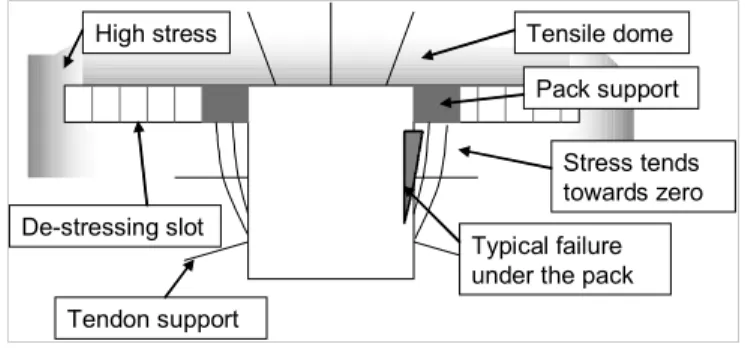
The T-shape is a way of de-stressing the tunnel sidewalls with a small off reef slot. The width of the slot is determined by both the width and the height of the development end to be wide enough to de-stress the sidewalls of the tunnel, typically less than 15 m wide. The slot is supported with elongates and packs on the slot shoulders. The tunnel is developed underneath the slot, holing constantly in the slot. The tunnel sidewalls and hangingwall can be supported with tendons.
At the corner between the slot and the tunnel the stress tends towards zero. As the pack is loaded, the vertical stress on the tunnel sidewalls is increased, but the horizontal stress remains virtually zero. This results in slabbing of the sidewalls and the sidewalls tend to deteriorate over time. The slabbing can be contained with mesh and lacing on tendon support in the sidewalls, but installing the tendons into the broken up de-stressed sidewalls remains a problem. This problem can be solved by installing sets and voidfill in the T-shape concurrent with the development of the T-shape. The width of the tunnel is then increased to allow for sidewall movement. The sets and voidfill are installed to control the movement.
Figure 3. T-shape tunnel De-stressing slot
Stress tends towards zero Pack support
Typical failure under the pack Tendon support
Tensile dome High stress
3.3 On reef slot
Both quasi-static and seismic damage are related to the field stress levels in the rockmass in the immediate rock walls of the excavation in relation to the strength of the rock (the rock strength is influenced by the existence of discontinuities like joints). For given rock mass strength and conditions, rock failure, including co-seismic damage can therefore be prevented by reducing the field stress levels. In access ways this can be achieved by overstoping the access way. Where a tunnel is laid out to be developed underneath a pillar, a de-stressing slot is mined on reef to afford the tunnel similar protection as for a follow behind tunnel. The de-stressing slot must be completed before the tunnel is developed. Several such slots have been established at TauTona and where these slots have been mined to the correct size, the associated access ways have remained stable for extended time periods. The size of the slot is proportional to the depth of the tunnel in the footwall of the slot. For a tunnel planned 40m in the footwall of for instance a 40m wide stability pillar or bracket pillar, the width of the slot must be approximately 80m wide – there is no pillar left…
3.4 Off reef slot
When an on-reef slot is impossible or impractical, an off-reef slot can be mined. The same guidelines as for an on-reef slot applies, but the size of the slot can be managed by managing the vertical distance between the slot and the tunnel elevation. This method of stabilising access ways has been implemented with success on TauTona Mine. In each case the tunnel had to be supported with an integrated support system of long anchors, mesh and lacing and shotcrete to cater for the stress changes during the overstoping process. 4
The next step - Umbrella Slot
4.1 The 93 access tunnel
Towards the eastern border of TauTona Mine, two major geological features, namely the Spotted Dick Horst Dyke and the Davey fault have been identified. These features trend parallel to each other diagonally from northeast to southwest across the eastern parts of the lease area. The normal distance between the fault and dyke is approximately 290m, leaving room for one diagonal mining longwall between the two features. The 97-99 Longwall mining strategy was adapted to do just that and is mining on apparent dip, with an angle of approximately 25° above strike between the Spotted Dick Horst Dyke and the Davey
fault. The stability pillars on either sides of the longwall were designed to act as both stability pillars and bracket pillars on the geological features. As discussed before, the bracket pillars reduce the seismic hazard to the longwall mining, but the access ways must traverse these pillars to bring the new infrastructure to the stopes. One of these ends is the 93 level access tunnel.
Figure 4. Position of the planned 93 access tunnel through the pillar on the Spotted Dick Horst Dyke The expected stress levels on the 93 level elevation through the pillar was modelled with the Map3D computer simulation program. From the stress
analysis
results, insight onto the field stress related tothe mining was gained.
Figure 5. Map3D stress analysis results
The mining strategy for the mining east of the current 99B Longwall position requires the 93 level access tunnel to be stable until 2014 (10 years). To ensure the long-term stability of this tunnel the seismic hazard associated with the Spotted dick Horst Dyke must also be considered. Large magnitude seismic
93 access tunnel
Spotted Dick Horst Dyke
Davey Fault
97-99 Longwall
N
91-94 Longwall (mined out)
99 B Longwall
Driefontein mining
events have occurred on the dyke as the pillar was formed. Furthermore seismic history on TauTona Mine has shown that large magnitude seismic events sometimes occur on pillars in the back areas, especially those pillars that incorporate major geological features.
To reduce the seismic hazard to the 93 Level access way, it was decided to reduce the stress on the tunnel by mining a de-stressing slot above the tunnel elevation. At the pillar position, the middling between the tunnel and the reef horizon would be 35m, requiring a 70m wide on-reef slot. The slot could not be started in time to ensure establishment of the slot before the pillar would be formed. It was therefore decided to de-stress the tunnel with an off-reef slot after the pillar has been formed. The required size of the off-reef slot is smaller than that of the on-reef slot as the off reef slot could be mined at a much reduced middling to the tunnel elevation. Map3D modelling was used to simulate a 20m wide slot 7m above the planned tunnel elevation.
Figure 6. Stress reduction on the tunnel elevation due to the 20m wide off-reef slot (Map3D)
To limit the stress changes and therefore the support requirements in the tunnel due to the overstoping, it was decided to mine the de-stressing slot concurrent with and leading the development of the tunnel. This was named the Umbrella Slot (Murphy 2001).
4.2 The Umbrella Slot layout
The slot layout indicates a 20m wide twin gully stope 7m above the tunnel (refer to Figure 7). The slot must be established in de-stressed ground before mining it through the high stress zone. This is to ensure that the access infrastructure to the slot remains stable until the slot has been established. The slot is established from two ore passes developed to the planned gully positions (refer to Figure 8). The ore passes are then
connected on the slot elevation and the connection ledged to establish the slot to its correct size. A travellingway is developed to hole into the connecting gully. The slot is then advanced in the required direction and the tunnel developed to the mine’s development standards, but to remain 7m behind the advancing slot.
Figure 7. The Umbrella Slot layout
Figure 8. Sequence to establish the slot 1
2 3
4 1. Develop t/way and boxholes 2. Connect
3. Ledge 4. Stope 1
2 3
4 1. Develop t/way and boxholes 2. Connect
3. Ledge 4. Stope
Planned position of the 93 level access tunnel trough pillar
Planned position of the umbrella cut
Stress reduction on the tunnel elevation due to the umbrella cut
Step 1 Step 2
60 MPa 120 MPa
20m
7m
45º 45º
4.3 Supporting the slot
The slot support standard is similar to the twin gully north side support standard implemented at TauTona, but no backfill is installed. Waste filling is done instead.
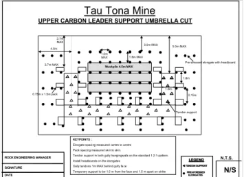
Figure 9. Support standard for Umbrella Slot 4.4 The Experience so far
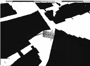
The ground conditions where the slot was started were poor due to the intersection of two major joint sets. Additional tendon support (splitsets) were installed in the connecting gully, but during the ledging phase falls of ground from the hangingwall occurred between the tendon support. This exposed the splitsets and it was decided to install sets in the gully and replace the access infrastructure as soon as possible.
Figure 10. Photo of the exposed splitsets in the connecting gully during the ledging phase
Connecting the ore passes with a wide raise, allowing for the installation of support on the ledges while establishing the connecting gully, would be a better option to manage the ground conditions.
Because the slot was mined off reef, it was decided to keep the dimensions of the slot to a minimum, therefore the slot was mined flat. The slot was aimed for the shortest distance through the pillar and no cognisance was taken of the strike direction of the strata. This resulted in the slot being mined below strike. Once the slot was advancing in the required direction, poor ground conditions and falls of ground from the hangingwall slowed down production and caused minor injuries to two of our workers. The combined effect of the mining direction and slot being mined flat, led to the angular intersection of the mining with the strata and unstable triangular wedges were created. It was subsequently decided to change the mining direction more towards strike and mine the slot on the dip of the strata. The slot span was then increased to 30m to ensure proper overstoping of the tunnel area (refer to Figure 11).
Figure 11. Increased slot span 2.15m
1.0m MAX 1.6m MAX
3.0m MAX
3.7m MAX
5.0m MAX
0.75m x 1.5m pack
Pre-stressed elongate with headboard
Tendon support
KEYPOINTS :
Elongate spacing measured centre to centre Pack spacing measured skin to skin.
Tendon support in both gully hangingwalls on the standard 1:2:1-pattern. Install headboards on the elongates
Gully tendons 1m MAX behind gully face
Temporary support to be 1.0 m from the face and 1.5 m apart on strike
UPPER CARBON LEADER SUPPORT UMBRELLA CUT Tau Tona Mine
4.0m
Muckpile 4.5m MAX
3.7m MAX
1.8m
N/S
N.T.S.
ROCK ENGINEERING MANAGER SIGNATURE DATE
ROCK ENGINEERING MANAGER SIGNATURE DATE
LEGEND
TENDON SUPPORT PRE-STRESSED
ELONGATES
LEGEND
TENDON SUPPORT PRE-STRESSED
ELONGATES 1.6m
20m 30m
7m
45º 45º
21º 20m
30m
7m
45º 45º
5 Conclusions
5.1 The Umbrella Slot is a viable alternative to ensure the long term stability of access ways through high stress abutments and has some advantages compared to other alternatives: 5.1.1 Integrated support system. The access tunnel
remains highly stressed and failure of this system has been recorded. The Umbrella Slot de-stresses the access tunnel and reduces the seismic hazard to the access tunnel.
5.1.2 T-shape. With a T-shape the tunnel is part of the slot (holing continuously into the slot), making it difficult to support the hangingwall and sidewalls and to inspect the hangingwall during making safe procedures. The Umbrella Slot is below the slot instead of part of the slot and a reinforced zone can be created with tendon support in the hangingwall and sidewalls of the tunnel.
5.1.3 On reef slot: The size of an on-reef slot is dictated by the middling between the tunnel and the reef horizon. The Umbrella Slot span can be reduced by bringing it closer to the tunnel elevation. Furthermore where a fault has displaced the reef, an on-reef slot is often impossible or impractical. Here the Umbrella Slot is a viable alternative.
5.1.4 Off reef slot: Where an off reef slot is mined over the tunnel after the tunnel has been developed, stress changes on the tunnel can cause failure to the tunnel and this must be catered for with serious secondary and tertiary support. The Umbrella cut is mined concurrent with and ahead of the tunnel, resulting in the tunnel being developed in de-stressed ground and no further stress changes are expected.
5.2 Cognisance of strata control issues must be taken when mining the slot:
5.2.1 it may be better to establish the connecting gully with a wide end
5.2.2 in dipping strata it must be considered to mine the slot in the strike direction and on the dip angle
6 Future work
The 93 Umbrella Slot access through the pillar on the Spotted Dick Horst Dyke will be monitored to determine it’s success in ensuring the long-term stability of this access way.
6.1 Seismicity will continually be monitored. 6.2 Two wire extensometers (one in the
hangingwall and one in the eastern sidewall) will be installed in the 93 access tunnel underneath the slot to monitor ground movement. The extensometers will be connected to the ISSI data transfer system to allow continuous monitoring of ground movement associated with seismic events. 7 Acknowledgements
The author would like to thank the management of Anglogold Ashanti for permission to publish this paper and Shaun Murphy for his assistance.
8 References
Murphy S.K. Stability of tunnels in a seismically active deep level mining environment (2002). International Seminar on Deep and High Stress Mining