Trademarks:
All terms used in this document that are known to be trademarks or service marks have been noted as such. Pirelli cannot attest to the accuracy of this information. Other product and corporate names used in this document that may be trademarks or service marks of other companies are used only for explanation and to the owner’s benefit, without intent to infringe. Use of a term in this document should not be regarded as affecting the validity of any trademark or service mark.
This publication is subject to change without notice. Pirelli reserves the right to make changes to equipment design and system components as well as system documentation and literature as progress in engineering, manufacturing methods, or other circumstances may warrant.
This publication is intended solely for informational and instructional purposes. Refer to the above as to its possible uses. It constitutes neither a contract with the user hereof nor a warranty or guarantee with regard to any of the Pirelli products described herein nor shall it be construed to grant a license or any other rights under any proprietary rights to information or material included herein. Pirelli hereby expressly disclaims any warranty or guarantee, whether express or implied, with regard to items described herein. Any contract, license, or warranty between Pirelli and the user hereof is created solely by separate legal documents.
i OGU 930500105-A1
(C) (2006) Pirelli Broadband Solutions S.p.A. All Rights Reserved. Proprietary Use Pursuant to Cover Page Instructions. DISCUS™ Multiplay Wireless VoIP AG
CONTENTS
Welcome 1
About this Guide 1
Naming Convention 1
Conventions 1
Introduction 3
Introduction 3
Package Contents 3
Router Advantages 6
Minimum System and Component Requirements 6
Front Panel 7
Rear Panel 8
Hardware Installation 11
Introduction 11
Positioning the Router 11
Installing Micro Filters 12
Powering up the router 13
Connecting the Router 13
Setting Up Your Computer 19
INSTALL Software 19
Ethernet Connection 20
Ethernet Connection >> TCP/IP Protocol Installation 20
Ethernet Connection >> MS Windows 98SE, ME, 2000 20
Ethernet Connection >> MS Windows XP 22
Ethernet Connection >> MAC OS 10.X 23
USB Connection 24
USB Connection >> MS Windows 24
USB Connection >> MAC OS 10.x 25
Wi-Fi connection 26
Router Configuration 29
ii OGU 930500105-A1
(C) (2006) Pirelli Broadband Solutions S.p.A. All Rights Reserved. Proprietary Use Pursuant to Cover Page Instructions.
Quick Setup Section 35
Point-to-point protocol over Ethernet (PPPoE) 36
Point-to-point protocol over ATM (PPPoA) 37
Routed Ethernet Connection over ATM (ETHoA) 37
Bridged Ethernet Connection over ATM (ETHoA) 37
No Internet Connection 37
Wireless 37
Administrator 38
Network Connections Section 39
LAN Bridge 40
LAN Bridge >> General 40
LAN Bridge >> Settings 41
LAN Bridge >> Routing 44
LAN Bridge >> Bridging 45
LAN Bridge >> Advanced 46
LAN Hardware Ethernet Switch 47
LAN Hardware Ethernet Switch >> General 47
LAN Hardware Ethernet Switch >> Settings 47
LAN Hardware Ethernet Switch >> HW Switch 48
LAN Hardware Ethernet Switch >> Advanced 49
LAN USB 50
LAN USB >> General 50
LAN USB >> Settings 50
LAN USB >> Advanced 51
LAN Wireless 802.11g Access Point 52
LAN Wireless 802.11g Access Point >> General 52
LAN Wireless 802.11g Access Point >> Settings 53
LAN Wireless 802.11g Access Point >> Wireless 54
LAN Wireless 802.11g Access Point >> Advanced 59
WAN DSL 59
WAN DSL >> General 59
WAN DSL >> Settings 60
Security Section 61
General 62
Access Control 64
Port Forwarding 65
DMZ Host 68
Port Triggering 69
Web Site Restrictions 69
iii OGU 930500105-A1
(C) (2006) Pirelli Broadband Solutions S.p.A. All Rights Reserved. Proprietary Use Pursuant to Cover Page Instructions. DISCUS™ Multiplay Wireless VoIP AG
NAT 70
Connections 71
Advanced Filtering 72
Security Log 73
Voice over IP Section 75
Line Settings 75
Speed Dial 76
Monitoring 77
Advanced 77
Quality of Service Section 81
General 81
Traffic Priority 82
Traffic Shaping 84
DSCP Settings 85
802.1p Settings 87
Class Statistics 87
Advanced Section 89
About Discus 90
Backup and Restore 91
Certificates 92
Configuration File 93
DNS Server 94
Date and Time 94
Diagnostics 95
Discus Firmware Upgrade 97
Disk Management 98
File Server 99
IP Address Distribution 99
Network Objects 101
PPPoE Relay 102
Personal Domain Name (Dynamic DNS) 102
Print Server 103
Protocols 103
RADIUS 104
Reboot 105
Remote Administration 105
Restore Defaults 107
Routing 108
iv OGU 930500105-A1
(C) (2006) Pirelli Broadband Solutions S.p.A. All Rights Reserved. Proprietary Use Pursuant to Cover Page Instructions.
SSH 109
Scheduler Rules 110
System Settings 111
Universal Plug and Play 113
Users 114
System Monitoring Section 117
Network Connections 117
System Log 118
CPU 119
Troubleshooting 121
Basic Connection Checks 121
Browsing to the Router Configuration Screens 121
Connecting to the Internet 122
Forgotten Password and Reset to Factory Defaults 122
Wireless Networking 122
Frequently Asked Questions 123
Safety Information 124
IP Addressing 126
Technical Specifications 128
We
lc
o
m
e
(C) (2006) Pirelli Broadband Solutions S.p.A. All Rights Reserved. Proprietary Use Pursuant to Cover Page Instructions.
1 OGU 930500105-A1
Welcome
ABOUT THIS GUIDE This guide describes how to install and configure the DISCUS™
Mul-tiplay Wireless VoIP AG. This guide is intended for use by those responsible for installing and setting up network equipment; conse-quently, it assumes a basic working knowledge of LANs (Local Area Networks) and Internet Routers.
NAMING CONVENTION Throughout this guide, the DISCUS Multiplay Wireless VOIP AG is
referred to as the “Wireless Router”. Category 5 Ethernet Cables are referred to as Ethernet Cables throughout this guide.
CONVENTIONS Table 1 and Table 2 list conventions that are used throughout this
guide.
TABLE 1. Notice Icons
Icon Notice Type Description
Information note Information that describes important features or instructions.
(C) (2006) Pirelli Broadband Solutions S.p.A. All Rights Reserved. Proprietary Use Pursuant to Cover Page Instructions.
2 OGU 930500105-A1 Welcome
Caution Information that alerts you to potential loss of data or potential damage to an application, system, or device.
Warning Information that alerts you to potential personal injury.
TABLE 2. Text Conventions
Convention Description
The words “enter” and “type” When you see the word “enter” in this guide, you must type something, and then press Return or Enter. Do not press Return or Enter when an instruction simply says “type.” Keyboard key names If you must press two or more keys simultaneously, the key
names are linked with a plus sign (+). Example: Press Ctrl+Alt+Del
Words in italics Italics are used to: • Emphasize a point.
• Denote a new term at the place where it is defined in the text.
• Identify menu names, menu commands, and software button names. Examples: “From the Help menu, select Contents. Click OK.”
TABLE 1. Notice Icons
Introduction
(C) (2006) Pirelli Broadband Solutions S.p.A. All Rights Reserved. Proprietary Use Pursuant to Cover Page Instructions.3 OGU 930500105-A1
Introduction
INTRODUCTION The DISCUS™ Multiplay Wireless VoIP AG is designed to provide
a cost-effective means of sharing a single broadband Internet con-nection between several wired and wireless computers. The Router also provides protection in the form of an electronic “firewall” prevent-ing anyone outside of your network from seeprevent-ing your files or damag-ing your computers. The Router offers VoIP functionalities through 2 VoIP channels allowing you to use existing analog phones and a fall-back to old telephony at loss of power, WAN, Internet or VoIP.
The DISCUS™ Multiplay Wireless VoIP AG is an ADSL2+ router, targeted to residential environments SOHO customers, that provides routed broadband services from a single and modular access point. The DISCUS™ Multiplay Wireless VoIP AG is the ideal solution for: 1. Connecting multiple PCs and Video game consoles;
2. Sharing broadband internet connections with all home computers; 3. Sharing printers and peripherals;
4. Performing VoIP connections.
PACKAGE CONTENTS Your new DISCUS™ Multiplay Wireless VoIP AG ADSL2+ Router
kit contains the related hardware and software. In it you will find: 1. One DISCUS™ Multiplay Wireless VoIP AG unit
2. One Table Support
3. One Power Supply adapter 4. One ADSL splitter micro filter 5. One USB cable
4
(C) (2006) Pirelli Broadband Solutions S.p.A. All Rights Reserved. Proprietary Use Pursuant to Cover Page Instructions.
OGU 930500105-A1 Introduction
6. One phone cable 7. One Ethernet cable 8. One installation CD-ROM 9. One Quick Guide
TABLE 1. Kit Material
Quantity DESCRIPTION
1 DISCUS™ Multiplay Wireless VoIP AG
1 Power Supplier
1 Ethernet Cable
1 USB Cable
1 Phone Cord
1 CD-ROM
DISCUS™ Multiplay Wireless VoIP AG
(C) (2006) Pirelli Broadband Solutions S.p.A. All Rights Reserved. Proprietary Use Pursuant to Cover Page Instructions.
5 OGU 930500105-A1
Introduction
If any of these items are missing or damaged, please contact your retailer. It implements an “always-on” high speed Asymmetric Digital Subscriber Line (ADSL2/2+) connection to the telephone line on the WAN side, as well several local connectivity technologies on the LAN side:
• Four switched 10/100 Base-TX Ethernet ports
• One Universal Serial Bus 1.1 (USB) connection to a host PC • One USB 2.0 Host port for external USB peripherals
• One IEEE 802.11b/g Wireless LAN access point • Two FXS ports to analog phones
• One FXO port to wall phone socket
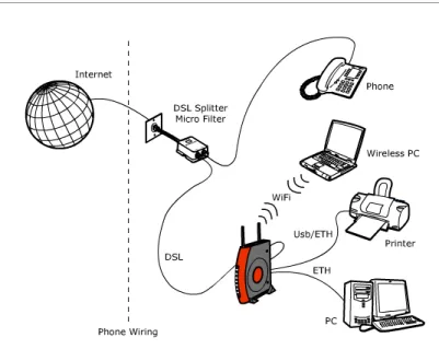
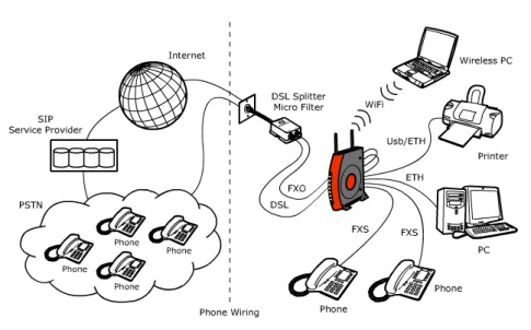
Figure 2 shows a sample network, while in Figure 2 an existing SIP account case is shown: your Router becomes your connection to the Internet. Connec-tions can be made directly to the Router expanding the number of computers you can have in your network.
FIGURE 1. Sample Home Network
1 ADSL Splitter Micro Filter
1 Table Support
6
(C) (2006) Pirelli Broadband Solutions S.p.A. All Rights Reserved. Proprietary Use Pursuant to Cover Page Instructions.
OGU 930500105-A1 Introduction
FIGURE 2. Sample Home Network (existing SIP account case)
ROUTER ADVANTAGES The advantages of the Router include:
• Shared Internet connection for both wired and wireless computers • High speed 802.11b/g wireless networking
• No need for a dedicated, “always on” computer serving as your Internet con-nection
• Cross-platform operation for compatibility with Windows and Macintosh com-puters (see Technical description for supported platforms).
• Easy-to-use, Web-based setup and configuration • Centralization of all network address settings (DHCP)
• a Virtual server to enable remote access to Web, FTP, and other services on your network
• a Security — Firewall protection — against Internet hacker attacks and encryption to protect wireless network traffic
• VoIP functionalities supporting existing analog phones
• Communication fallback of ADSL to analog lines in case of power or hard-ware faults (if supported by your network operator)
• a multi-language GUI.
MINIMUM SYSTEM AND COMPONENT
REQUIREMENTS
Your Router requires that the computer(s) and components in your network be configured with at least the following:
• A computer with the Operating Systems that support TCP/IP networking pro-tocols: Windows 98SE, Windows ME, Windows 2000, Windows XP 32bit or MAC 10.x
DISCUS™ Multiplay Wireless VoIP AG
(C) (2006) Pirelli Broadband Solutions S.p.A. All Rights Reserved. Proprietary Use Pursuant to Cover Page Instructions.
7 OGU 930500105-A1
Introduction
• An Ethernet 10Mbps or 10/100 Mbps NIC for each computer to be connected to one of the three Ethernet port at the rear of the Router
• An USB 2.0 port
• As optional, an 802.11b/g wireless NIC • At least, 60MB of free hard disk space • At least, 128 MB of RAM
• Supported Browsers: Internet Explorer 5.5 or higher, Netscape 4.7 or higher
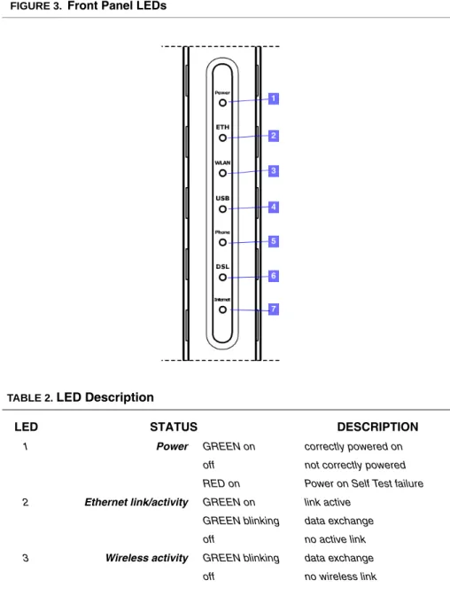
FRONT PANEL The front panel of the Router contains seven indicator lights (LEDs) that help to
describe the state of networking and connection operations. FIGURE 3. Front Panel LEDs
TABLE 2. LED Description
LED STATUS DESCRIPTION
1 Power GREEN on correctly powered on off not correctly powered RED on Power on Self Test failure 2 Ethernet link/activity GREEN on link active
GREEN blinking data exchange off no active link 3 Wireless activity GREEN blinking data exchange
8
(C) (2006) Pirelli Broadband Solutions S.p.A. All Rights Reserved. Proprietary Use Pursuant to Cover Page Instructions.
OGU 930500105-A1 Introduction
REAR PANEL The rear panel of the Router contains a reset button, a power adapter socket,
four LAN ports, one ADSL port, one USB device port and one USB Host port, one FXO port and two FXS ports.
GREEN on link established 4 USB link/activity GREEN on link active
GREEN blinking data exchange off no active link
5 Phones off Phone line 1 or 2 not regis-tered
GREEN on At least one of the FXS ports has been registered with a SIP Proxy server
GREEN blinking One of the phones is off-hook 6 DSL line activity off no DSL line link is active
GREEN on connected
GREEN blinking connection in progress 7 Internet activity GREEN on link active
GREEN blinking data exchange off no active link
RED All Internet connection attempts failed
TABLE 2. LED Description
LED STATUS DESCRIPTION
Do not force the antenna beyond its mechanical stops. Rotating the antenna further may cause dam-age.
DISCUS™ Multiplay Wireless VoIP AG
(C) (2006) Pirelli Broadband Solutions S.p.A. All Rights Reserved. Proprietary Use Pursuant to Cover Page Instructions.
9 OGU 930500105-A1
Introduction
FIGURE 4. Rear Panel LEDs
TABLE 3. Port Description
PORT DESCRIPTION
a Phone DSL connector (ADSL2/2+) b FXO port
c FXS ports d USB 1.1 port
e USB 2.0 port for external peripherals f Four Ethernet ports 10/100 Mbps g Reset to factory default button h Power button
10
(C) (2006) Pirelli Broadband Solutions S.p.A. All Rights Reserved. Proprietary Use Pursuant to Cover Page Instructions.
Hardw
a
re Installation
(C) (2006) Pirelli Broadband Solutions S.p.A. All Rights Reserved. Proprietary Use Pursuant to Cover Page Instructions.
11 OGU 930500105-A1
Hardware
Installation
INTRODUCTION This chapter will guide you through a basic installation of the Router
including:
1. Positioning the DISCUS™ Multiplay Wireless VoIP AG 2. Installing Micro Filters
3. Connecting the Router to your network
4. Setting up your computer for networking with the Router
POSITIONING THE ROUTER You should place the Router in such a location to ensure that:
• It is located near an electrical outlet and a phone wall socket • Water or moisture cannot enter the case of the unit
• It is out of direct sunlight and away from sources of heat
• The cabling is away from power lines, fluorescent lighting fixtures, and sources of electrical noise such as radios, transmitters and broadband amplifiers.
Please read carefully the Safety Information in Appendix “A”
A multimedia guided tour on how to connect your device and install the router’s drivers is available on CD-ROM. It is recommended to follow CD-ROM procedures to easy up device setup.
(C) (2006) Pirelli Broadband Solutions S.p.A. All Rights Reserved. Proprietary Use Pursuant to Cover Page Instructions.
12 OGU 930500105-A1 Hardware Installation
• It is centrally located to the wireless computers that will connect to the Router. A suitable location might be on top of a high shelf to optimize wire-less connections to computers in both horizontal and vertical directions, allowing wider coverage
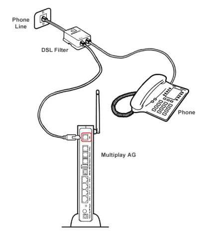
INSTALLING MICRO FILTERS
Before beginning installation you must locate devices in your house requiring a DSL filter such as phones, fax machines, answering machines, dial-up modems, Satellite TV dialers or monitored security systems and attach a DSL filter to any one of them sharing the same phone line as your DSL modem. To install DSL filters please follow these steps:
1. Disconnect the phone cable from the telephone wall socket
2. Insert the phone cable into the DSL filter socket identified with a phone symbol
3. Insert the DSL filter cable into the telephone wall socket
FIGURE 1. Micro Filter Installation
You do not need to attach a DSL filter to unused wall sockets.
1
2
DISCUS™ Multiplay Wireless VoIP AG
(C) (2006) Pirelli Broadband Solutions S.p.A. All Rights Reserved. Proprietary Use Pursuant to Cover Page Instructions.
13 OGU 930500105-A1
Hardware Installation
POWERING UP THE ROUTER
To power up the Router:
1. Plug the power adapter into the power adapter socket located on the rear panel of the Router
2. Plug the power adapter into a standard electrical wall socket 3. Wait for the power LED to turn steady green
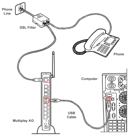
CONNECTING THE ROUTER The first step to install the router is to physically connect it to the telephone
socket and then to connect it to a computer - by means of an Ethernet or an USB connection - to be able to access the Internet
To connect the phone cable:
1. Connect one end of the phone cable into the DSL filter socket identified with a computer symbol
2. Connect the other end of the phone cable into the DSL socket of the Router FIGURE 2. Phone Cable Connection
(C) (2006) Pirelli Broadband Solutions S.p.A. All Rights Reserved. Proprietary Use Pursuant to Cover Page Instructions.
14 OGU 930500105-A1 Hardware Installation
1. Connect one end of the Ethernet cable into one of the four Ethernet sockets on the rear of the Router
2. Connect the other end of the ethernet cable into the Ethernet plug of your computer
FIGURE 3. Ethernet Cable Connection
To connect the USB cable:
1. Connect one end of the USB cable into the USB socket on the rear of the Router.
DISCUS™ Multiplay Wireless VoIP AG
(C) (2006) Pirelli Broadband Solutions S.p.A. All Rights Reserved. Proprietary Use Pursuant to Cover Page Instructions.
15 OGU 930500105-A1
Hardware Installation
FIGURE 4. USB Cable Connection
2. Launch USB driver setup available on CD-ROM.
To do this, browse till x:\driver folder (where “x” is the CD-ROM drive unit let-ter); from this folder, according to your Operating System, launch the follow-ing executable:
WINDOWS >> “x:\driver\windows\setup.exe” MACOS X >> “x:\driver\macosx\Package.sit”
and follow setup instructions.
3. The setup software will invite you to plug the other end of the USB cable into the USB socket of your computer
(see “USB Connection” ).
(C) (2006) Pirelli Broadband Solutions S.p.A. All Rights Reserved. Proprietary Use Pursuant to Cover Page Instructions.
16 OGU 930500105-A1 Hardware Installation
To perform for the very first time a USB connection or an Ethernet one to the Router, it is recommended you to launch the setup application on CD-ROM and follow the step by step procedure.
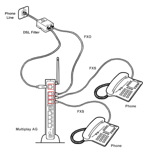
In the case your provider will supply to you a SIP account, it will be needed to properly connect the FXS and FXO ports. In detail you must follow these steps, after micro filters installation:
1. Connect one end of the first phone cable into the DSL filter socket identified with a computer symbol
2. Connect the other end of the first phone cable into the DSL socket of the Router
3. Connect one end of the second phone cable into the DSL filter socket identi-fied with a phone symbol
4. Connect the other end of the second phone cable into the WALL socket of the Router (FXO connection)
5. Connect a maximum of two analog phones to the Phone 1 or Phone 2 sock-ets of the Router (FXS connection)
DISCUS™ Multiplay Wireless VoIP AG
(C) (2006) Pirelli Broadband Solutions S.p.A. All Rights Reserved. Proprietary Use Pursuant to Cover Page Instructions.
17 OGU 930500105-A1
Hardware Installation
FIGURE 5. FXS and FXO connections
Connect to your PC with Ethernet or USB cables as described in the previous steps.
(C) (2006) Pirelli Broadband Solutions S.p.A. All Rights Reserved. Proprietary Use Pursuant to Cover Page Instructions.
Setting Up Y
o
ur Computer
(C) (2006) Pirelli Broadband Solutions S.p.A. All Rights Reserved. Proprietary Use Pursuant to Cover Page Instructions.
19 OGU 930500105-A1
Setting Up Your
Computer
The Router has the ability to dynamically allocate network addresses to the computers on your network, using DHCP. However, your com-puters need to be configured correctly for this to take place. To change the configuration of your computers to allow this, follow the instructions in this chapter.
INSTALL SOFTWARE The very first time you set up your computer, we recommend you to
use setup software available on CD-ROM.
Setup software offers a guided product tour, a step by step hardware installation guide, a software installation guide and setup depending on your connection choice (USB or ETHERNET) and a driven user registration with DSL Internet connection line check.
Setup software allows, for supported Microsoft Windows Operating Systems, to setup automatically your computer Ethernet settings. To launch Setup, insert Setup software CD-ROM in CD-ROM unit: if the autoplay function is enabled it will start automatically, otherwise click once on the “Run...” item in “Start” menu. In the opened panel type “x:\install.exe” where x is your CD-ROM drive letter.
Before installing the DISCUS™ Multiplay Wireless VoIP AG software please close all appli-cations to avoid any conflict.
(C) (2006) Pirelli Broadband Solutions S.p.A. All Rights Reserved. Proprietary Use Pursuant to Cover Page Instructions.
20 OGU 930500105-A1 Setting Up Your Computer
ETHERNET CONNECTION In case you already established a connection with your Router a first time and/or
you do need to set up manually a connection to your Router, please follow the instructions described in this chapter. You will be guided to set up an Ethernet connection to the Router. To do so, first you have to verify the existence of a TCP/IP protocol stack and, then, according to your Operating System, to estab-lish an Ethernet connection to it. This connection will require you to enable your computer to receive from the Router its own IP Address automatically: in such a case, the Router acts like the DHCP server in your local network.
ETHERNET CONNECTION >> TCP/IP PROTOCOL INSTALLATION
This procedure requires the TCP/IP protocol installed on your computer. Refer to the following chapters and to your Windows or MacOS operating systems manuals.
Microsoft Windows 98SE, ME, 2000.
1. Put in the CD-ROM drive your Windows installation CD-ROM
2. Starting from Start -> Settings -> Control Panel -> Network Control Panel, make a double click on the Network icon
3. Select Configuration -> TCP/IP and then click on the Add button
4. Select Protocols, click on Add button and choose Microsoft TCP/IP. Then click on the OK button
5. After the computer reboots, you're ready to configure the TCP/IP settings Configure the Network adapter to obtain automatically an IP address Microsoft Windows XP.
1. Put in the CD-ROM drive your Windows installation CD-ROM
2. Starting from Start -> Settings -> Control Panel make a double click on the Network icon.
3. Select Protocol and click on the Add button. Select Microsoft and TCP/IP, then click on the OK button.
4. Configure the Network adapter to obtain automatically an IP address. Apple MacOS 10.x.
TCP/IP is installed on a MacOS system as part of Open Transport.
ETHERNET CONNECTION >> MS WINDOWS 98SE, ME, 2000
To configure TCP/IP on these Operating Systems follow these steps:
1. Select Start -> Settings -> Control Panel and make a double click on the Net-work icon.
DISCUS™ Multiplay Wireless VoIP AG
(C) (2006) Pirelli Broadband Solutions S.p.A. All Rights Reserved. Proprietary Use Pursuant to Cover Page Instructions.
21 OGU 930500105-A1
Setting Up Your Computer
FIGURE 1. Local Area Connection Properties
3. Select the IP Address Tab, then check to obtain an automatically IP address. Click on OK button.
(C) (2006) Pirelli Broadband Solutions S.p.A. All Rights Reserved. Proprietary Use Pursuant to Cover Page Instructions.
22 OGU 930500105-A1 Setting Up Your Computer
4. A system reboot will be required to make the changes real.
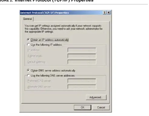
ETHERNET CONNECTION >> MS WINDOWS XP
To configure TCP/IP on MS Windows XP Operating System follow these steps: 5. Select Start -> Settings -> Control Panel and make a double click on the
Net-work icon.
6. Select Protocols ->TCP/IP then click on Properties button. FIGURE 3. Local Area Connection Properties
7. Select the General Tab, then check to obtain an automatically IP address. Click on OK button.
DISCUS™ Multiplay Wireless VoIP AG
(C) (2006) Pirelli Broadband Solutions S.p.A. All Rights Reserved. Proprietary Use Pursuant to Cover Page Instructions.
23 OGU 930500105-A1
Setting Up Your Computer
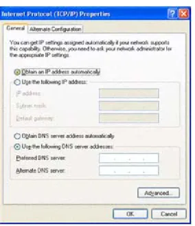
FIGURE 4. Internet Protocol (TCP/IP) Properties
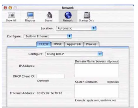
ETHERNET CONNECTION >> MAC OS 10.X
To configure TCP/IP on MAC OS 10.x follow these steps:
1. Open the Apple Menu -> System Preferences and select Network. 2. From the Show drop down list, according to the type of connection used,
select Built-in Ethernet. 3. Select the TCP/IP tab.
4. Select DHCP from the Configure pop-up menu to have a dynamic IP address.
(C) (2006) Pirelli Broadband Solutions S.p.A. All Rights Reserved. Proprietary Use Pursuant to Cover Page Instructions.
24 OGU 930500105-A1 Setting Up Your Computer
FIGURE 5. Network panel on MAC OS 10.x
5. Click Apply Now.
6. Click on the Register button to save the changes in the Control Panel. 7. Enter http://192.168.1.1/ in the address bar of your browser to open the
DIS-CUS™ Multiplay Wireless VoIP AG Home Page.
USB CONNECTION To connect your first Computer to the DISCUS™ Multiplay Wireless VoIP AG
using USB port, you have to install the Router’s USB driver on your computer.
USB CONNECTION >> MS WINDOWS
Before connecting the USB Cable to the USB Port of the DISCUS™ Multiplay Wireless
VoIP AG you have to run the setup software and to follow the instructions. Connect the USB Cable only when requiredfrom the installation software.
Only one Windows or Macintosh computer can be directly connected to the DISCUS™ Mul-tiplay Wireless VoIP AG using the USB connection. Additional computers can be added to your network using the others connection such as Ethernet or Wi-Fi.
DISCUS™ Multiplay Wireless VoIP AG
(C) (2006) Pirelli Broadband Solutions S.p.A. All Rights Reserved. Proprietary Use Pursuant to Cover Page Instructions.
25 OGU 930500105-A1
Setting Up Your Computer
1. Browse the Setup CD-ROM and install the USB Windows driver selecting the folder x:\driver\windows (where x is the CD-ROM driver unit).
2. Make a double click on setup.exe file to start driver setup procedure. 3. When the message “NOW CONNECT THE USB CABLE” should appear,
connect the USB cable from a free USB port of the computer to the DIS-CUS™ Multiplay Wireless VoIP AG USB port.
4. Enter http://192.168.1.1/ in the address bar of your browser to open the DIS-CUS™ Multiplay Wireless VoIP AG Home Page.
USB CONNECTION >> MAC OS 10.X
1. Browse the CD-ROM and install the USB MAC OS 10.x selecting the folder x:\driver\macosx (where x is the CD-ROM drive unit).
2. Make a double click on the Package.sit zipped file to start the unzip.
3. Select the folder Macintosh HD:osxdrv:Install USB ADSL. 4. Make a double click on the install script file.
5. Restart the computer clicking on the Restart button.
6. When appear the message “NOW CONNECT THE USB CABLE”, connect the USB cable from a free USB port of the computer to the DISCUS™ Multi-play Wireless VoIP AG USB port.
7. Verify that your computer is configured to obtain an IP address automatically via DHCP mode, following the next steps.
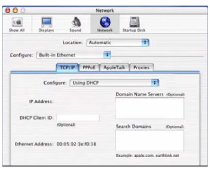
8. Open the Apple Menu -> System Preferences and select Network. 9. From the Show drop down list, according to the type of connection used,
select Built-in USB ADSL. 10.Select the TCP/IP tab.
11.Select Using DHCP from the Configure pop-up menu to have a dynamic IP address.
If the system requires the path, select the hard disk main folder, normally named Macintosh HD.
(C) (2006) Pirelli Broadband Solutions S.p.A. All Rights Reserved. Proprietary Use Pursuant to Cover Page Instructions.
26 OGU 930500105-A1 Setting Up Your Computer
FIGURE 6. Network Panel
12.Click Apply Now.
13.Click on the Register button to save the changes in the Control Panel. 14.Enter http://192.168.1.1/ in the address bar of your browser to open the
DIS-CUS™ Multiplay Wireless VoIP AG Home Page.
WI-FI CONNECTION
1. Install your wireless adapter according to the manufacturer’s instructions and verify that your computer is set to obtain an IP address automatically (DHCP mode).
2. In the configuration window of your wireless adapter scan the wireless net-work (marked with the relevant SSID name) present in your physical environ-ment.
3. Select the SSID of the DISCUS™ Multiplay Wireless VoIP AG (default value: openrg).
4. Complete the configuration of the wireless adapter with the same parame-ters of the DISCUS™ Multiplay Wireless VoIP AG which are:
It requires a computer with 802.11b/g (Wi-Fi Certified) wireless adapter installed.
You will need to properly configure your adapter to communicate with the DISCUS™ Multi-play Wireless VoIP AG according to the configuration rules.
DISCUS™ Multiplay Wireless VoIP AG
(C) (2006) Pirelli Broadband Solutions S.p.A. All Rights Reserved. Proprietary Use Pursuant to Cover Page Instructions.
27 OGU 930500105-A1
Setting Up Your Computer
• RF channel; automatically detect (default = 6) • WEP encryption enable or disable (default = Disable) • WEP key size
• WEP key used
5. To check the connection, connect to the DISCUS™ Multiplay Wireless VoIP AG Home Page, entering http://192.168.1.1/ in the address bar of your browser.
(C) (2006) Pirelli Broadband Solutions S.p.A. All Rights Reserved. Proprietary Use Pursuant to Cover Page Instructions.
Router Configur
ation
(C) (2006) Pirelli Broadband Solutions S.p.A. All Rights Reserved. Proprietary Use Pursuant to Cover Page Instructions.
29 OGU 930500105-A1
Router
Configuration
INTRODUCTION The Router setup program is web based, which means that it is
accessed through your web browser. To access to Router’s web server:
1. Launch your web browser on the computer
2. Enter the following URL in the location or address field of your browser: http://192.168.1.1
Access to DSL router configuration pages is controlled through user accounts. The default one is the admin userwith unrestricted access to change and view configuration of the DSL Router.
You will be asked to choose the Router interface language between English, French, Russian, Spanish, Korean, Japanese, Chinese, Hebrew, German and Italian and to insert a User Name and a Pass-word: insert them to access to Router’s configuration panels.
The Router comes with a default IP address (192.168.1.1). If you change it, please take note of the new Router’s IP address, otherwise a “Reset to Factory Default” operation should be done to be able to access again to the Router.
The default username and password are both set to “admin”. It is recommended to change these default values. Make sure you remember your user name and password, since this is the only way you will be able to manage your Router
(C) (2006) Pirelli Broadband Solutions S.p.A. All Rights Reserved. Proprietary Use Pursuant to Cover Page Instructions.
30 OGU 930500105-A1 Router Configuration
If not already configured, at the first login the Quick Setup panel will be shown to configure the Router connection parameters, otherwise the Home page will be opened as shown in Figure 1.
The Home page contains a menu on the left - always available in all the web pages which is the starting point for any Router’s configuration.
The complete menu has the following main items:
1. Home: it shows a graphical representation of your network.
2. Quick Setup: it allows to quickly perform the Router’s connection setup 3. Network Connections: it shows the status of network connections
allow-ing to modify them or to create new ones 4. Security: it allows to set security settings 5. Voice over IP: it allows to set VoIP accounts 6. QoS: it gathers all QoS parameters and settings
7. Advanced: it allows the access to the advanced configuration panels and to define Router parameters devoted to user access, log management, Router’s time, Backup Router’s configuration, etc.
8. System Monitoring: a menu to show and run diagnostic test for trouble-shooting or system behavior analysis and to access to Device Information and Statistics
9. Logout: to logout from Router’s session.
In order to submit the changes of most of device parameters you have to click the Apply but-ton to save permanently your changes. In some case a Router’s reboot is required.
DISCUS™ Multiplay Wireless VoIP AG
(C) (2006) Pirelli Broadband Solutions S.p.A. All Rights Reserved. Proprietary Use Pursuant to Cover Page Instructions.
31 OGU 930500105-A1
Router Configuration
FIGURE 1. Router’s Home Page
Every object in the network map is a link for jumping directly to the object set-tings pages. A tooltip, by moving the mouse over these network objects, helps in having an immediate comprehension of pointed object name and type.
(C) (2006) Pirelli Broadband Solutions S.p.A. All Rights Reserved. Proprietary Use Pursuant to Cover Page Instructions.
32 OGU 930500105-A1 Router Configuration
In the following table a list of all available network objects and related descrip-tion is shown.
TABLE 1. Available Network Objects
Map Symbol Description
It represents the Internet
It represents your DSL Wide Area Network (WAN) connection. Click this icon to configure the WAN interface
It represents your Ethernet Wide Area Network (WAN) con-nection or an Ethernet Local Area Network (LAN) concon-nection. Click this icon to configure the WAN interface or the Ethernet LAN device
It represents the gateway's Firewall. The height of the wall cor-responds to the security level currently selected: Minimum, Typical or Maximum. Click this icon to configure security set-tings
It represents a USB LAN connection. Click this icon to configure network parameters for the USB LAN device
It represents a Wireless LAN connection. Click this icon to con-figure network parameters for the Wireless LAN device
It represents a bridge connected in the home network. Click this icon to view the bridge's underlying devices.
DISCUS™ Multiplay Wireless VoIP AG
(C) (2006) Pirelli Broadband Solutions S.p.A. All Rights Reserved. Proprietary Use Pursuant to Cover Page Instructions.
33 OGU 930500105-A1
Router Configuration
It represents a computer (host) connected in the home net-work. Each computer connected to the network appears below the network symbol of the network through which it is con-nected. Click an icon to view network information for the corre-sponding computer.
It represents a printer that is connected to the Router and is shared by network users. Click the icon to view the printer's settings.
It represents a file server that is connected to the Router and is shared by network users. Click the icon to view the file server configuration.
TABLE 1. Available Network Objects
(C) (2006) Pirelli Broadband Solutions S.p.A. All Rights Reserved. Proprietary Use Pursuant to Cover Page Instructions.
Quic
k Setup Section
(C) (2006) Pirelli Broadband Solutions S.p.A. All Rights Reserved. Proprietary Use Pursuant to Cover Page Instructions.
35 OGU 930500105-A1
Quick Setup
Section
This chapter will describe the Quick Setup Section accessible from the Home Page of the DISCUS™ Multiplay Wireless VoIP AG upon user authentication to the Router.
The Quick Setup enables speedy and accurate configuration of your Internet connection and other important parameters.
After the setup described in this chapter, you can immediately start using your Router to:
1. Share a broadband connection among multiple users (HTTP, FTP, Telnet, NetMeeting) and between all of the computers connected to your home network.
2. Build a home network by connecting additional PCs and network devices to the gateway.
3. Share resources (file servers, printers, etc.) between computers in the home network using their names; auto-learning DNS enables DIS-CUS™ Multiplay Wireless VoIP AG to automatically detect the net-work identification names of the LAN PCs, enabling mutual
communication using names, not IP addresses.
4. Control network parameters, including DHCP, DNS and WAN settings.
5. View network status, traffic statistics, system log and more.
(C) (2006) Pirelli Broadband Solutions S.p.A. All Rights Reserved. Proprietary Use Pursuant to Cover Page Instructions.
36 OGU 930500105-A1 Quick Setup Section
6. Allow access from the Internet to games and other services provided by computers in the home network.
7. Prohibit computers in the home network from accessing selected services on the Internet.
8. Block access to specific Internet Web sites from your home network.
FIGURE 1. Quick Setup Panel
Your WAN connection(s) can be configured using one of the following meth-ods. Read the configuration instructions relevant to you, by selecting your con-nection method from the list below and clicking its section link:
1. Point-to-point protocol over Ethernet (PPPoE)
2. Point-to-point protocol over ATM (PPPoA)
3. Routed Ethernet Connection over ATM (ETHoA)
4. Bridged Ethernet Connection over ATM (ETHoA)
5. No Internet connection
POINT-TO-POINT PROTOCOL OVER ETHERNET (PPPOE)
To configure the Point-to-point protocol over Ethernet, follow these steps: 1. Select 'Point-to-point protocol over Ethernet (PPPoE)' from the 'Connection Type'
combo-box.
2. Your Internet Service Provider (ISP) should provide you with the Login user name and Login password.
3. If your board features a DSL connection, you will see an 'Automatic PVC Scan' check box. Select this check box to enable the automatic configuration of the VPI, VCI and encapsulation parameters (relevant to DSL connections).
DISCUS™ Multiplay Wireless VoIP AG
(C) (2006) Pirelli Broadband Solutions S.p.A. All Rights Reserved. Proprietary Use Pursuant to Cover Page Instructions.
37 OGU 930500105-A1
Quick Setup Section
POINT-TO-POINT PROTOCOL OVER ATM (PPPOA)
To configure the Point-to-point protocol over ATM, follow these steps: 1. Select 'Point-to-point protocol over ATM (PPPoA)' from the 'Connection Type'
combo-box
2. Your Internet Service Provider (ISP) should provide you with the following informa-tion:
- Login user name - Login password
- By default, the 'Automatic PVC Scan' check box is enabled, which means that the Router configures the VPI, VCI and encapsulation parameters automatically. If you would like to configure these parameters manually, uncheck this check box. - Specify the VPI and VCI values.
- Select the encapsulation method from the combo-box. You can choose among the following methods: LLC, VCMux and VCMux - HDLC
ROUTED ETHERNET CONNECTION OVER ATM (ETHOA)
To configure the Routed Ethernet connection over ATM, follow these steps: 1. Select 'Routed Ethernet Connection over ATM (ETHoA)' from the 'Connection
Type' combo-box
2. Your Internet Service Provider (ISP) should provide you with the following informa-tion:
- Specify the value of the VPI and VCI parameters.
- Select the encapsulation method from the combo-box. You can choose among the following methods: LLC, VCMux.
- Select the Internet Protocol: Most Internet Service Providers (ISPs) provide dynamic IP addresses, hence the default "Obtain an IP Address Automatically". Should this not be the case, select the "Use the Following IP Address" option. The screen will refresh. Enter the IP Address, Subnet Mask, Default Gateway, and DNS Server details provided to you by your ISP.
BRIDGED ETHERNET CONNECTION OVER ATM (ETHOA)
To configure the Bridged Ethernet Connection over ATM (ETHoA), follow these steps:
1. Select 'Bridged Ethernet Connection over ATM (ETHoA)' from the 'Connection Type' combo-box
2. Your Internet Service Provider (ISP) should provide you with the following informa-tion:
- Specify the value of the VPI and VCI parameters.
- Select the encapsulation method from the combo-box. You can choose among the following methods: LLC, VCMux
NO INTERNET CONNECTION
Select 'No Internet Connection' from the 'Connection Type' combo-box. Choose this connection type if you do not have an Internet connection, or if you want to disable all existing connections.
WIRELESS Click the 'Enabled' check box to enable your wireless connection. Specify the
(C) (2006) Pirelli Broadband Solutions S.p.A. All Rights Reserved. Proprietary Use Pursuant to Cover Page Instructions.
38 OGU 930500105-A1 Quick Setup Section
ADMINISTRATOR In this section it is necessary to specify the administrator's e-mail in the 'E-mail'
Netw
or
k Connections Section
(C) (2006) Pirelli Broadband Solutions S.p.A. All Rights Reserved. Proprietary Use Pursuant to Cover Page Instructions.
39 OGU 930500105-A1
Network
Connections
Section
This chapter will describe the Network Connections Section acces-sible from the Home Page of the DISCUS™ Multiplay Wireless VoIP AG.
This section (see Figure 1) is intended to present a summary of the Router's connections, such as WAN and LAN (i.e. Ethernet, USB, Wireless) interfaces.
DISCUS™ Multiplay Wireless VoIP AG supports various network connections, both physical and logical. The Network Connections screen enables you to configure the various parameters of your phys-ical connections, the LAN and WAN, and create new connections, using tunneling protocols over existing connections, such as PPP and VPN.
Press the 'Advanced' button to expand the screen and display all connection entries.
(C) (2006) Pirelli Broadband Solutions S.p.A. All Rights Reserved. Proprietary Use Pursuant to Cover Page Instructions.
40 OGU 930500105-A1 Network Connections Section
FIGURE 1. Network Connections Panel
LAN BRIDGE The LAN bridge connection is used to combine several LAN devices under
one virtual network. For example, creating one network for LAN Ethernet and LAN wireless devices.
Please note, that when a bridge is removed, its formerly underlying devices inherit the bridge's DHCP settings. For example, the removal of a bridge that is configured as DHCP client, automatically configures the LAN devices formerly constituting the bridge as DHCP clients, with the exact DHCP client configura-tion.
LAN BRIDGE >> GENERAL To view and edit the LAN bridge connection settings, click the 'LAN Bridge' link
in the 'Network Connections' screen. The 'LAN Bridge Properties' screen will appear, displaying a detailed summary of the connection's parameters, under the 'General' tab. These parameters can be edited in the rest of the screen's tabs, as described in the following sections.
DISCUS™ Multiplay Wireless VoIP AG
(C) (2006) Pirelli Broadband Solutions S.p.A. All Rights Reserved. Proprietary Use Pursuant to Cover Page Instructions.
41 OGU 930500105-A1
Network Connections Section
FIGURE 2. LAN Bridge >> General Panel
LAN BRIDGE >> SETTINGS General. This section displays the connection's general parameters. It is
recom-mended not to change the default values unless familiar with the networking concepts they represent. Since your gateway is configured to operate with the default values, no parameter modification is necessary.
(C) (2006) Pirelli Broadband Solutions S.p.A. All Rights Reserved. Proprietary Use Pursuant to Cover Page Instructions.
42 OGU 930500105-A1 Network Connections Section
FIGURE 3. LAN Bridge >> Settings Panel
Schedule. By default, the connection will always be active. However, you can
configure scheduler rules in order to define time segments during which the connection may be active. Once a scheduler rule(s) is defined, this field changes to a combo-box, allowing you to choose between the available rules.
Network. Select whether the parameters you are configuring relate to a WAN,
LAN or DMZ connection, by selecting the connection type from the combo-box.
Physical Address. The physical address of the network card used for your
net-work. Some cards allow you to change this address.
MTU. MTU is the Maximum Transmission Unit. It specifies the largest packet
size permitted for Internet transmission. In the default setting, Automatic, the gateway selects the best MTU for your Internet connection. Select "Automatic by DHCP" to have the DHCP determine the MTU. In case you select "Manual", it is recommended to enter a value in the 1200 to 1500 range.
Internet Protocol. Select one of the following Internet protocol options from the
DISCUS™ Multiplay Wireless VoIP AG
(C) (2006) Pirelli Broadband Solutions S.p.A. All Rights Reserved. Proprietary Use Pursuant to Cover Page Instructions.
43 OGU 930500105-A1
Network Connections Section
- No IP Address: Select 'No IP Address' if you require that your gateway have no IP address. This can be useful if you are working in an environment where you are not connected to other networks, such as the Internet.
- Obtain an IP Address Automatically: Your connection is configured by default to act as a DHCP client. You should keep this configuration in case your service provider supports DHCP, or if you are connecting using a dynamic IP address. The server that assigns the gateway with an IP address, also assigns a subnet mask. You can override the dynamically assigned subnet mask by selecting the 'Override Subnet Mask' and specifying your own mask instead. You can press the 'Release' button to release the current leased IP address. Once the address has been released, the button text changes to 'Renew'. Use the 'Renew' button to renew the leased IP address.
- Use the Following IP Address: Your connection can be configured using a per-manent (static) IP address. Your service provider should provide you with such an IP address and subnet mask.
DNS Server. Domain Name System (DNS) Server is the method by which Web
site domain names are translated into IP addresses. You can configure the con-nection to automatically obtain a DNS server address, or specify such an address manually, according to the information provided by your ISP. To configure the connection to automatically obtain a DNS server address, select 'Obtain DNS Server Address Automatically' from the 'DNS Server' drop down menu.
To manually configure DNS server addresses, select 'Use the Following DNS Server Addresses' from the 'DNS Server' drop down menu. Specify up to two different DNS server address, one primary, another secondary.
IP Address Distribution. The 'IP Address Distribution' section allows you to
con-figure the gateway's Dynamic Host Configuration Protocol (DHCP) server parameters. The DHCP automatically assigns IP addresses to network PCs. If you enable this feature, make sure that you also configure your network PCs as DHCP clients. Select one of the following options from the 'IP Address Distribu-tion' combo-box:
DHCP Server.
Start IP Address: The first IP address that may be assigned to a LAN host. Since the gateway's default IP address is 192.168.1.1, this address must be 192.168.1.2 or greater.
End IP Address: The last IP address in the range that can be used to automati-cally assign IP addresses to LAN hosts.
Subnet Mask: A mask used to determine to what subnet an IP address belongs. An example of a subnet mask value is 255.255.0.0.
(C) (2006) Pirelli Broadband Solutions S.p.A. All Rights Reserved. Proprietary Use Pursuant to Cover Page Instructions.
44 OGU 930500105-A1 Network Connections Section
Lease Time In Minutes: Each device will be assigned an IP address by the DHCP server for this amount of time, when it connects to the network. When the lease expires the server will determine if the computer has disconnected from the network. If it has, the server may reassign this IP address to a newly-con-nected computer. This feature ensures that IP addresses that are not in use will become available for other computers on the network.
Provide Host Nameif Not Specified by Client: If the DHCP client does not have a host name, the gateway will automatically assign one for him.
DHCP Relay. Your gateway can act as a DHCP relay in case you would like to
dynamically assign IP addresses from a DHCP server other than your gateway's DHCP server. Note that when selecting this option you must also change Router's WAN to work in routing mode.
1. After selecting 'DHCP Relay' from the drop down menu, a 'New IP Address' link will appear: Click the 'New IP Address' link. The 'DHCP Relay Server Address' screen will appear.
2. Specify the IP address of the DHCP server.
3. Click 'OK' to save the settings.
Disabled. Select 'Disabled' from the combo-box if you would like to statically
assign IP addresses to your network computers.
LAN BRIDGE >> ROUTING You can choose to setup your gateway to use static or dynamic routing.
Dynamic routing automatically adjusts how packets travel on the network, whereas static routing specifies a fixed routing path to neighboring destinations.
DISCUS™ Multiplay Wireless VoIP AG
(C) (2006) Pirelli Broadband Solutions S.p.A. All Rights Reserved. Proprietary Use Pursuant to Cover Page Instructions.
45 OGU 930500105-A1
Network Connections Section
Routing. Select 'Advanced' or 'Basic' routing.
Routing Mode. Select one of the following routing modes:
• Route: Use route mode if you want your gateway to function as a router between two networks. • NAPT: Network Address and Port Translation (NAPT) refers to network address translation
involving the mapping of port numbers, allowing multiple machines to share a single IP address. Use NAPT if your LAN encompasses multiple devices, a topology that necessitates port transla-tion in additransla-tion to address translatransla-tion.
Device Metric. The device metric is a value used by the gateway to determine
whether one route is superior to another, considering parameters such as band-width, delay, and more.
Default Route. Select this check box to define this device as a the default route.
Routing Information Protocol (RIP). Select this check box to enable the Routing
Information Protocol (RIP). RIP determines a route based on the smallest hop count between source and destination. When RIP is enabled, select the follow-ing:
• Listen to RIP messages - select 'None', 'RIPv1', 'RIPv2' or 'RIPv1/2'.
• Send RIP messages - select 'None', 'RIPv1', 'RIPv2-broadcast' or 'RIPv2-multicast'.
Multicast - IGMP Proxy Internal. IGMP proxy enables the system to issue
IGMP host messages on behalf of hosts that the system discovered through standard IGMP interfaces. IGMP proxy enables the routing of multicast packets according to the IGMP requests of LAN devices asking to join multicast groups. Select the 'Multicast IGMP Proxy Internal' check-box to enable this feature.
Routing Table. Allows you to add or modify routes when this device is active.
Use the 'New Route' button to add a route or edit existing routes.
LAN BRIDGE >> BRIDGING This section allows you to specify the devices that you would like to join under
(C) (2006) Pirelli Broadband Solutions S.p.A. All Rights Reserved. Proprietary Use Pursuant to Cover Page Instructions.
46 OGU 930500105-A1 Network Connections Section
FIGURE 5. LAN Bridge >> Bridging Panel
Select the 'STP' check box to enable the Spanning Tree Protocol on the device. You should use this to ensure that there are no loops in your network configura-tion, and apply these settings in case your network consists of multiple switches, or other bridges apart from those created by the gateway.
LAN BRIDGE >> ADVANCED Internet Connection Firewall. Your gateway's firewall helps protect your
com-puter by preventing unauthorized users from gaining access to it through a net-work such as the Internet. The firewall can be activated per netnet-work connection. To enable the firewall on this network connection, select the 'Enabled' check box.
DISCUS™ Multiplay Wireless VoIP AG
(C) (2006) Pirelli Broadband Solutions S.p.A. All Rights Reserved. Proprietary Use Pursuant to Cover Page Instructions.
47 OGU 930500105-A1
Network Connections Section
Additional IP Addresses. You can add alias names (additional IP addresses) to
the gateway by clicking the 'New IP Address' link. This enables you to access the gateway using these aliases in addition to the 192.168.1.1
LAN HARDWARE ETHERNET SWITCH
A LAN Ethernet connection connects computers to the Router using Ethernet cables, either directly or via network hubs and switches.
LAN HARDWARE ETHERNET SWITCH >> GENERAL
To view and edit the LAN Ethernet connection settings, click the 'LAN Ethernet' link in the 'Network Connections' screen. The 'LAN Ethernet Properties' screen will appear, displaying a detailed summary of the connection's parameters, under the 'General' tab. These parameters can be edited in the rest of the screen's tabs, as described in the following sections.
FIGURE 7. LAN Hardware Ethernet Switch >> General Panel
LAN HARDWARE ETHERNET SWITCH >> SETTINGS
General. This section displays the connection's general parameters. It is
recom-mended not to change the default values unless familiar with the networking concepts they represent. Since your gateway is configured to operate with the default values, no parameter modification is necessary.
Schedule. By default, the connection will always be active. However, you can
configure scheduler rules in order to define time segments during which the connection may be active. Once a scheduler rule(s) is defined, this field changes to a combo-box, allowing you to choose between the available rules.
(C) (2006) Pirelli Broadband Solutions S.p.A. All Rights Reserved. Proprietary Use Pursuant to Cover Page Instructions.
48 OGU 930500105-A1 Network Connections Section
FIGURE 8. LAN Hardware Ethernet Switch >> Settings Panel
Network. Select whether the parameters you are configuring relate to a WAN,
LAN or DMZ connection, by selecting the connection type from the combo-box.
Physical Address. The physical address of the network card used for your
net-work. Some cards allow you to change this address.
MTU. MTU is the Maximum Transmission Unit. It specifies the largest packet
size permitted for the transmission. In the default setting, Automatic, the gate-way selects the best MTU for your Internet connection. Select "Automatic by DHCP" to have the DHCP determine the MTU. In case you select "Manual", it is recommended to enter a value in the 1200 to 1500 range.
LAN HARDWARE
ETHERNET SWITCH >> HW SWITCH
DISCUS™ Multiplay Wireless VoIP AG
(C) (2006) Pirelli Broadband Solutions S.p.A. All Rights Reserved. Proprietary Use Pursuant to Cover Page Instructions.
49 OGU 930500105-A1
Network Connections Section
FIGURE 9. LAN Hardware Ethernet Switch >> HW Switch Panel
LAN HARDWARE ETHERNET SWITCH >> ADVANCED
Internet Connection Firewall. Your gateway's firewall helps protect your
com-puter by preventing unauthorized users from gaining access to it through a net-work such as the Internet. The firewall can be activated per netnet-work connection. To enable the firewall on this network connection, select the 'Enabled' check box.
(C) (2006) Pirelli Broadband Solutions S.p.A. All Rights Reserved. Proprietary Use Pursuant to Cover Page Instructions.
50 OGU 930500105-A1 Network Connections Section
Additional IP Addresses. You can add alias names (additional IP addresses) to
the gateway by clicking the 'New IP Address' link. This enables you to access the gateway using these aliases in addition to the 192.168.1.1
LAN USB The LAN USB connection allows you to connect a Windows PC to the Router
using a USB cable. Connect your gateway's USB slave port to a master port on the PC.
LAN USB >> GENERAL To view and edit the LAN USB connection settings, click the 'LAN USB' link in
the 'Network Connections' screen. The 'LAN USB Properties' screen will appear, displaying a detailed summary of the connection's parameters, under the 'General' tab. These parameters can be edited in the rest of the screen's tabs, as described in the following sections.
FIGURE 11. LAN USB >> General Panel
LAN USB >> SETTINGS General. This section displays the connection's general parameters. It is
recom-mended not to change the default values unless familiar with the networking concepts they represent. Since your gateway is configured to operate with the default values, no parameter modification is necessary.
DISCUS™ Multiplay Wireless VoIP AG
(C) (2006) Pirelli Broadband Solutions S.p.A. All Rights Reserved. Proprietary Use Pursuant to Cover Page Instructions.
51 OGU 930500105-A1
Network Connections Section
FIGURE 12. LAN USB >> Settings Panel
Schedule. By default, the connection will always be active. However, you can
configure scheduler rules in order to define time segments during which the connection may be active. Once a scheduler rule(s) is defined, this field changes to a combo-box, allowing you to choose between the available rules.
Network. Select whether the parameters you are configuring relate to a WAN,
LAN or DMZ connection, by selecting the connection type from the combo-box.
Physical Address. The physical address of the network card used for your
net-work. Some cards allow you to change this address.
MTU. MTU is the Maximum Transmission Unit. It specifies the largest packet
size permitted for the transmission.
LAN USB >> ADVANCED Internet Connection Firewall. Your gateway's firewall helps protect your
com-puter by preventing unauthorized users from gaining access to it through a net-work such as the Internet. The firewall can be activated per netnet-work connection. To enable the firewall on this network connection, select the 'Enabled' check box.
(C) (2006) Pirelli Broadband Solutions S.p.A. All Rights Reserved. Proprietary Use Pursuant to Cover Page Instructions.
52 OGU 930500105-A1 Network Connections Section
FIGURE 13. LAN USB >> Advanced Panel
Additional IP Addresses. You can add alias names (additional IP addresses) to
the gateway by clicking the 'New IP Address' link. This enables you to access the gateway using these aliases in addition to the 192.168.1.1
LAN WIRELESS 802.11G
ACCESS POINT DISCUS™ Multiplay Wireless VoIP AGsecurity. These include the IEEE 802.1x port-based authentication protocol, integrates multiple layers of wireless
RADIUS client, EAP-MD5, EAP-TLS, EAP-TTLS, EAP-PEAP, Wi-Fi Protected Access (WPA), WPA2, WPA and WPA2 (mixed mode) and industry leading Dis-cus Firewall and VPN applications. In addition, the Router’s built-in authentica-tion server enables home/SOHO users to define authorized wireless users without the need for an external RADIUS server.
LAN WIRELESS 802.11G ACCESS POINT >> GENERAL
To view and edit the LAN Wireless connection settings, click the 'LAN Wireless 802.11g Access Point' link in the 'Network Connections' screen. The 'LAN Wire-less 802.11g Access Point Properties' screen will appear, displaying a detailed summary of the connection's parameters, under the 'General' tab. These parameters can be edited in the rest of the screen's tabs, as described in the fol-lowing sections.
DISCUS™ Multiplay Wireless VoIP AG
(C) (2006) Pirelli Broadband Solutions S.p.A. All Rights Reserved. Proprietary Use Pursuant to Cover Page Instructions.
53 OGU 930500105-A1
Network Connections Section
FIGURE 14. LAN Wireless 802.11g Access Point >> General Panel
LAN WIRELESS 802.11G ACCESS POINT >> SETTINGS
General. This section displays the connection's general parameters. It is
recom-mended not to change the default values unless familiar with the networking concepts they represent. Since your gateway is configured to operate with the default values, no parameter modification is necessary.
(C) (2006) Pirelli Broadband Solutions S.p.A. All Rights Reserved. Proprietary Use Pursuant to Cover Page Instructions.
54 OGU 930500105-A1 Network Connections Section
FIGURE 15. LAN Wireless 802.11g Access Point >> Settings Panel
Schedule. By default, the connection will always be active. However, you can
configure scheduler rules in order to define time segments during which the connection may be active. Once a scheduler rule(s) is defined, this field changes to a combo-box, allowing you to choose between the available rules.
Network. Select whether the parameters you are configuring relate to a WAN,
LAN or DMZ connection, by selecting the connection type from the combo-box.
Physical Address. The physical address of the network card used for your
net-work. Some cards allow you to change this address.
MTU. MTU is the Maximum Transmission Unit. It specifies the largest packet
size permitted for Internet transmission. In the default setting, Automatic, the gateway selects the best MTU for your Internet connection. Select "Automatic by DHCP" to have the DHCP determine the MTU. In case you select "Manual", it is recommended to enter a value in the 1200 to 1500 range.
LAN WIRELESS 802.11G ACCESS POINT >> WIRELESS
Wireless Access Point
Use this section to define the basic wireless access point settings.
SSID. The SSID is the network name shared among all points in a wireless
net-work. The SSID must be identical for all points in the wireless netnet-work. It is case-sensitive and must not exceed 32 characters (use any of the characters on the keyboard). Make sure this setting is the same for