HCS Redundancy and High Availability
• Data Center Infrastructure, page 1 • Data Center Interconnect, page 2 • Geo-Redundancy, page 2
• Geo-Redundancy for Cisco Unified Communications Domain Manager, page 7 • Data Center Redundancy, page 15
• Application Redundancy, page 16 • Unified Communications, page 16 • Cisco HCS Management, page 18
Data Center Infrastructure
Cisco HCS leverages the Cisco Virtualized MultiServices Data Center (VMDC) for the data center architecture design. The VMDC system is the Cisco reference architecture for Infrastructure as a Service (IaaS) cloud deployments and utilizes a hierarchical network design for high availability and scalability. The hierarchical or layered DC design uses redundant switches at each layer of the network topology for device-level failover that creates a highly available transport between end nodes using the network. DC networks often require additional services beyond basic packet forwarding, such as Server Load Balancing (SLB), firewall, and intrusion prevention. These services might be introduced as modules populating a slot of one of the switching nodes in the network or as standalone appliance devices. Each service approach also supports the deployment of redundant hardware to preserve high availability standards set by the network topology. This layered approach is the basic foundation of the VMDC design to provide scalability, performance, flexibility, resiliency, and service assurance. VLANs and Virtual Routing and Forwarding (VRF) instances are used to provide customer isolation within the data center architecture, and routing protocols within the VRFs are utilized to interconnect the different networking and service devices.
Leveraging VMDC, the Cisco HCS system is built around the Cisco Unified Computing System (Cisco UCS), Nexus 1000V, Nexus 5000 and Nexus 7000 switches, multilayer Director Switch (MDS), Aggregation Services Router (ASR) 9000, ASR 1000, Adaptive Security Appliance (ASA) 5585-X or Adaptive Security Appliance Services Module (ASASM), Nexus 1000V Virtual Security Gateway (VSG), VMware vSphere, and supports several shared storage options such as EMC and NetApp.
For more information, see Cisco Virtualized MultiTenant Data Center, Version 2.2 Design Guide available athttp://www.cisco.com/go/vmdcandUC Virtualization Storage System Design Requirementsavailable at
http://docwiki.cisco.com/wiki/UC_Virtualization_Storage_System_Design_Requirements.
Data Center Interconnect
The term Data Center Interconnect (DCI) is relevant in all scenarios where you require different levels of connectivity between two or more data center locations to provide flexibility for deploying applications and resiliency schemes. Geo redundancy or high availability of a given data center requires infrastructure and applications running in multiple data centers to be available without any major down time. Several options are available to interconnect data centers in both active-active and active-standby deployment scenarios. There is a need to extend applications (IP/LAN extension) and datastores (SAN extension) across the data centers. In typical active-standby data center deployments, where the applications are brought up on the standby data center only after the primary data center has an outage, there is no need for LAN extension between data centers. You only need to extend the SAN for data store replication. In active-active data center deployments, where the applications are extended between data centers, there is the need for LAN and SAN extension between data centers. Stretching the network space across two or more data centers may be needed by clustering applications, which require Layer 2 connectivity between cluster nodes. Putting these nodes in separate data centers can help build resilience into the cloud. This also provides the flexibility of being able to shift compute resources around geographically as needs dictate.
Depending on application types, there are several possible data center interconnect methods:
•Layer 2 Extension: Provide a single Layer 2 domain across data centers. The data center applications are often legacy or use embedded IP addressing that drives Layer 2 expansion across data centers. Workload mobility and VMotion of virtual machines across data centers also requires Layer 2 extension.
•Layer 3 Extension (Recommended method): Provide routed connectivity between data centers used for segmentation and virtualization and redundant applications. This may be Layer 3 VPN-based connectivity or plain IP connectivity.
•SAN Extension: Storing and replicating data for business continuity, disaster recovery, and regulatory compliance. However, this presents different types of challenges and considerations because of the requirements in terms of distance and latency and the fact that Fiber Channel cannot natively be transported over an IP network.
For more information, seeCisco Validated Designs using Data Center Interconnect:http://www.cisco.com/ en/US/netsol/ns749/networking_solutions_sub_program_home.html.
Geo-Redundancy
Level 3 geo-redundancy (with no SAN mirroring) is offered in Cisco HCS deployments.
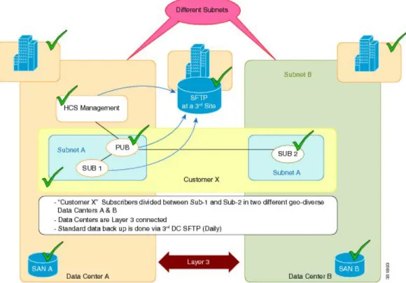
As shown in the following figure, in normal operation Level 3 geo-redundancy (with no SAN mirroring) includes the following:
•Two data centers with no real-time SAN mirroring
•Data Center A has its management layer and publishers and subscribers backed up to a third-party site through SFTP daily
•Load is shared between subscriber 1 and subscriber 2
HCS Redundancy and High Availability Data Center Interconnect
•Lower cost capital expenditure than with SAN mirroring
Figure 1: Normal Layer 3 Geo-Redundant Operation - No SAN Mirroring
When an outage occurs for a customer using Level 3 geo-redundancy, the following occurs:
•There is no call processing outage if the surviving data center can take the load.
•VM rebuild takes at least 4 hours.
•Restoring Unified Communications applications and resync takes at least another 4 hours.
•Total recovery time per Unified Communications cluster is 8+ hours. Outage also depends on time to schedule restore in addition to the restoration time. Not all VM restoration tasks can run in parallel due to input/output operations per second (IOPS).
•Total recovery time for HCS Management is approximately 8 hours. Outage also depends on time to schedule restore in addition to the restoration time. Not all VM restoration tasks can run in parallel due to input/output operations per second (IOPS).
•MACD outage until recovered is 8+ to 16+ hours (approximately 16+ hours for the first customer and approximately 8 hours for each subsequent customer based on all manual efforts).
•MACD outage is repeated after the affected data center is back in service.
•Cisco Unified Communications components and HCS management components must maintain same IP address during disaster recovery. Change of IP address during recovery isnotsupported, nor are there plans to support this in the future.
•For more information, seeRecover from Level 3 Geo-Redundant Design Outage, on page 4
HCS Redundancy and High Availability
Operational expenditures for Level 3 geo-redundancy with no SAN mirroring is as follows:
•Only periodic data backup is created.
•All disaster recovery is performed manually, including routing change.
•Procedure must be repeated after the affected data center is back in service.
Recover from Level 3 Geo-Redundant Design Outage
This procedure outlines the high-level steps that are performed to recover from an outage when using the Level 3 geo-redundant design (with no SAN mirroring).
Procedure
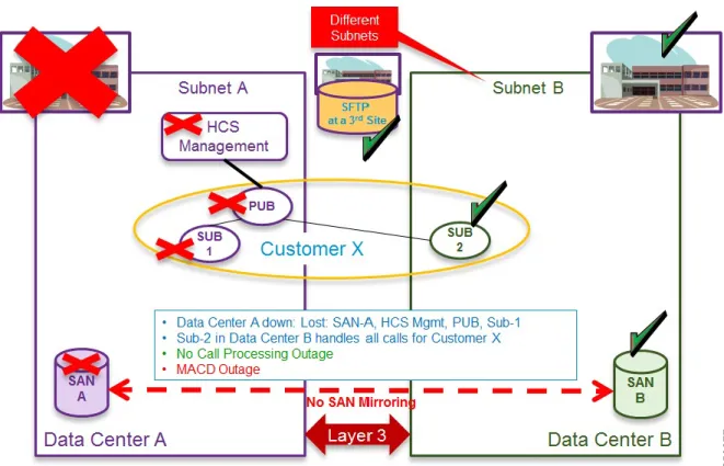
Step 1 Data Center A down–If Data Center A goes down, all HCS Management, publishers, and subscribers are down in Data Center A. There is no loss of call processing because subscriber 2 in Data Center B takes over. A MACD outage occurs.
Figure 2: Layer 3 Geo-redundant Design - Data Center A Down
Step 2 Implement manual network changes to allow subnet A in data center B.
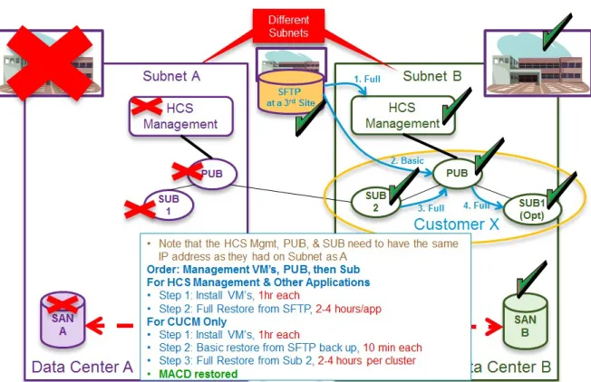
Step 3 Build virtual machines in Data Center B and restore from SFTP–Build the virtual machines in the following order: HCS Management first, then publishers, then subscribers.
HCS Redundancy and High Availability Recover from Level 3 Geo-Redundant Design Outage
The HCS Management, publishers and subscribers on Subnet B must use the same IP address as Subnet A.
Note
Figure 3: Layer 3 Geo-Redundant Design - Build VMs in DC B and Restore from SFTP
Estimated time to complete this step:
•For HCS Management and other applications–Time to install VMs: 1 hour each
•Full restore from SFTP: 2 to 4 hours for each application
•For Unified Communications Manager only–Time to install VMs: 1 hour each
•Basic restore from SFTP backup: 10 minutes each
•Full restore from subscriber 2: 2 to 4 hours for each cluster
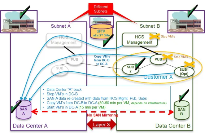
Step 4 Data Center A comes back online–When Data Center A comes back online, the VMs in Data Center B must be stopped. Start to recopy VMs from Data Center B to Data Center A (30 to 60 minutes for each VM). Data Center B VMs must be stopped before restarting Data Center A. Start VMs in Data Center A (15 minutes for each VM).
Manual network changes should be reverted.
Note
HCS Redundancy and High Availability
Figure 4: Layer 3 Geo-Redundant Design - Data Center A Comes Back Online
Figure 5: Layer 3 Geo-Redundant Design: Cisco HCS Management, Pub, Sub 1 Stopped in Data Center B
HCS Redundancy and High Availability Recover from Level 3 Geo-Redundant Design Outage
It may take many hours for Data Center B to get to MACD restored state. Therefore an alternative recovery option, if Data Center A will be offline for only a few hours (less than a total catastrophic destruction of Data Center A,) is to do nothing and simply restore Data Center A when it comes back online.
Note
Geo-Redundancy for Cisco Unified Communications Domain
Manager
This process applies to all versions of Cisco Unified Communications Domain Manager.
Note
Multinode Cluster with Unified Nodes
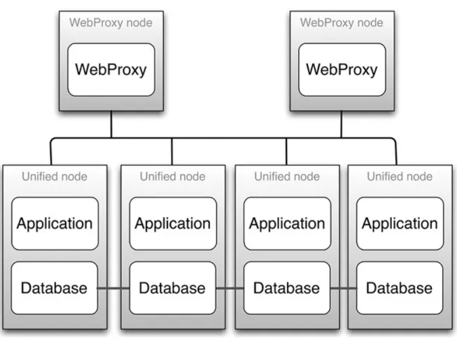
The recommended multinode deployment using Unified nodes has the following characteristics:
•Four Unified nodes - each node combining Application and Database roles - are clustered and split over two geographically disparate locations.
HCS Redundancy and High Availability
•Two Web Proxy nodes to provide High Availability that ensure an Application role failure is gracefully handled. It may be omitted if an external load balancer is available.
•Web Proxy and Unified nodes can be contained in separate firewalled networks.
•Database synchronization takes places between all Database roles, thus offering Disaster Recovery, and High Availability.
•All nodes in the cluster are active.
Primary and fall-back Secondary Database servers can be configured manually.
For a geo-redundant multinode deployment, please contact your Cisco support representative.
Note
To install a geo-redundant multinode solution, refer to theCisco Hosted Collaboration Solution, Release 10.6(1) Install Guide.
Note
Figure 6: A Graphical Representation of a Recommended Multinode Cluster
HCS Redundancy and High Availability Multinode Cluster with Unified Nodes
WebProxies can be configured to load balance across two or four Unified nodes.
Note
Multinode Cluster Hardware Specifications
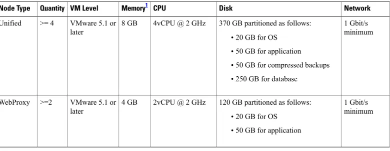
Migration from the Stand-Alone Cisco Unified Communications Domain Manager 10.6(x) system to a 4 Unified Node/2 WebProxy Node cluster is supported. The resource requirements for each configuration are provided in Table 1.
Table 1: Virtual Machine Requirements
Network Disk CPU Memory1 VM Level Quantity Node Type 1 Gbit/s minimum 370 GB partitioned as follows:
•20 GB for OS
•50 GB for application
•50 GB for compressed backups
•250 GB for database 4vCPU @ 2 GHz
8 GB VMware 5.1 or later
>= 4 Unified
1 Gbit/s minimum 120 GB partitioned as follows:
•20 GB for OS
•50 GB for application 2vCPU @ 2 GHz
4 GB VMware 5.1 or later
>=2 WebProxy
1 For the 4 Unified Node/2 WebProxy node deployments where the total number of end users is expected to exceed 100,000, it is recommended that 16 GB of RAM be provisioned for each Unified node. The recommended memory allocation for the WebProxy nodes does not change.
The size of the database storage partition supports the maximum deployment size for the release. Further increase in the size of the partition is not required when new customers are on-boarded.
To set up the disk requirements, the disk should be set up on the VMware GUI Resources tab where a disk can be created. This task should be done after the OVA import but prior to the boot of the system.
Alternative Geo-redundant Cluster Hardware Specification
Virtual machine requirements are specified in the table below.Network Disk CPU Memory VM Quantity Purpose 1Gbit/s recommended 150GB 2vCPU @ 2GHz 8GB >= VMWare 4.1 >= 2 Application nodes HCS Redundancy and High Availability
Network Disk CPU Memory VM Quantity Purpose 1Gbit/s recommended 150GB 2vCPU @ 2GHz 4GB >= VMWare 4.1 >= 2 WebProxy nodes 1Gbit/s recommended 160GB + 100GB dedicated
backup 2vCPU @ 2GHz 4GB >= VMWare 4.1 >= 3 Database nodes
Clustering Considerations
The cluster contains multiple nodes that can be contained in separate firewalled networks.
Open network ports on firewalls to allow internode communication. Port requirements are described in the Platform Guide.
All communication between nodes is encrypted.
Ports Node type
22 (SSH and SFTP), 80 (HTTP), 161 and 162 (SNMP), 443 and 8443 (HTTPS) WebProxy
22 (SSH and SFTP), 80 (HTTP), 161 and 162 (SNMP), 443 and 8443 (HTTPS), 27019, 27020, and 27030 (database)
Unified
•22/SSH is used for remote administration.
•80 and 443 are used for the web server.
•161 and 162 are used for sending and receiving SNMP.
•8443 is used for intercluster communication.
•27019, 27020, and 27030 are used for database queries and replication.
Cisco Unified Communications Domain Manager 10.6(x) Redundancy and
Disaster Recovery
High Availability (HA) is an approach to IT system design and configuration that ensures Cisco Unified Communications Domain Manager 10.6(x) is operational and accessible during a specified timeframe. High Availability is achieved using redundant hardware and resources. Cisco recommends the use of two physical data centers, where the primary site contains three VMs and the secondary site contains three VMs. If there is a failure, an automatic failover to the secondary DR (Disaster Recovery) site takes place.
Web server proxy nodes perform load-balancing between application roles, so that load is distributed. During provisioning, the web server proxy is provided with all the IP addresses of the application nodes. The web server software then does load balancing among these nodes, according to its configuration. If a node fails to
HCS Redundancy and High Availability Clustering Considerations
respond in a set time, the proxy sends the transaction to another node. If an Application role is lost, the WebProxy transparently bypasses the faulty Application role.
The proxy web server that is configured to be located in the primary site normally load balances to the two unified nodes in the primary site. The proxy web server falls back to the two nodes in the Disaster Recovery site if the nodes in the primary site are down. The web proxy nodes in the secondary site defaults load balancing to the two unified nodes configured for the secondary site.
Data is replicated between unified node roles, and role failure is recoverable. Data replication is done using the database replication facility. Automatic failover between unified node roles occurs while there is greater than 50% unified node role availability. Once there is insufficient role availability, the system must be manually reprovisioned.
HA can be increased by adding nodes to the cluster. Application performance and availability can be increased by adding more application role servers.
Backups can be scheduled to run automatically across the cluster. Backups include application data, configuration, and software. Backups can take place to both local disk and remote network location. Every node upgrade includes a snapshot backup which allows any upgrade to be rolled back.
Cluster Failure Scenarios
The status of the cluster can be displayed from the command line on any node using the command:
cluster status
The system can automatically signal email and/or SNMP events in the event that a node is found to be down. Refer to the diagrams in the section on deployments.
Loss of an Application role
The Web Proxy will keep directing traffic to alternate application role servers. There is no downtime.
Loss of a Web Proxy
Communication via the lost Web Proxy will fail, unless some another load balancing infrastructure is in place (DNS, external load balancer, VIP technology). The node can be installed as a HA pair so that the VMware infrastructure will restore the node if it fails. Downtime takes place while updating the DNS entry or returning the Web Proxy to service. For continued service, traffic can be directed to an alternate Web Proxy or directly to an Application node if available. Traffic can be directed manually (i.e., network elements must be configured to forward traffic to the alternate Web Proxy).
In the sections that follow, it is assumed that the partner has assigned the recommended database (DB) weights as follows:
•Primary Unified Node (UN1) database weight = 40
•Secondary Unified Node (UN2) database weight = 30
•Secondary Unified Node (UN3) database weight = 20
•Secondary Unified Node (UN4 ) database weight = 10
The Unified CDM system automatically assigns Voting Members to the Unified Nodes based on their DB weights noted previously:
HCS Redundancy and High Availability
•Secondary Unified Node (UN2) Voting Members = 2
•Secondary Unified Node (UN3) Voting Members = 2
•Secondary Unified Node (UN4 ) Voting Members = 1
The relative size of the database weights determines the hierarchy of the nodes in a failure scenario. The Unified Node (UN) with the highest database weight is the Primary.
The number of Voting Members is used to establish a quorum, and is the basis for the behavior of the system in a multi-node failure scenario. There are a total of 7 Voting Members (2 + 2 +2 +1) in the cluster by default. The subsequent tables illustrate the behavior of the system in various failure scenarios. In all cases where a UN has failed, it is assumed that the entire node (and therefore the database function referenced earlier in this section) is out of service. Any in-flight transactions on nodes that failed will be lost.
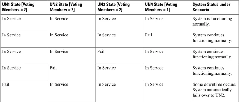
Table 2: Single Unified Node Failure Scenarios
System Status under Scenario
UN4 State [Voting Members = 1] UN3 State [Voting
Members = 2] UN2 State [Voting
Members = 2] UN1 State [Voting
Members = 2]
System is functioning normally. In Service In Service In Service In Service System continues functioning normally. Fail In Service In Service In Service System continues functioning normally. In Service Fail In Service In Service System continues functioning normally. In Service In Service Fail In Service
Some downtime occurs. System automatically fails over to UN2. In Service
In Service In Service
Fail
Table 3: Multiple Unified Node Failure Scenarios
System Status under Scenario Voting Members in
Service UN4 State [Voting
Members = 1] UN3 State [Voting
Members = 2] UN2 State [Voting
Members = 2] UN1 State [Voting
Members = 2]
System is functioning normally. 7 In Service In Service In Service In Service Manual Intervention is required to restore service. 3 In Service In Service Fail Fail
HCS Redundancy and High Availability Cluster Failure Scenarios
System Status under Scenario Voting Members in
Service UN4 State [Voting
Members = 1] UN3 State [Voting
Members = 2] UN2 State [Voting
Members = 2] UN1 State [Voting
Members = 2]
System continues functioning normally. 4 Fail Fail In Service In Service Manual Intervention is required to restore service. 3 In Service Fail Fail In Service System continues functioning normally. 4 Fail In Service Fail In Service
In all of the scenarios, whenever 50% or more Voting Members are in service, the system will remain in service. Manual steps will be required to restore the cluster.
Loss of a Database role
If the primary Database service is lost, the system will automatically revert to the secondary Database. The primary and secondary database nodes can be configured via the command-line interface using
database weight <ip> <weight>. For example, the primary can be configured with a weight of 50, and the secondary with a weight of 20. If both the primary and the secondary Database servers are lost, the remaining Database servers will vote to elect a new primary Database server. There is downtime (usually no more than a few seconds) during election and failover, with a possible loss of data in transit (a single transaction). The GUI web-frontend transaction status can be queried to determine if any transactions failed. The downtime for a Primary to Secondary failover is significantly less and the risk of data loss likewise reduced. A full election (with higher downtime and risk) is therefore limited only to cases of severe outages where it is unavoidable. Although any values can be used, for 4 database nodes the weights: 4, 3, 2, 1 is recommended.
Loss of a site
Unified and Database nodes have database roles. The status of the roles can be displayed usingcluster status. If 50% or more of the database roles are down, then there is insufficient availability for the cluster to function as is. Either additional role servers must be added, or the nodes with down roles must be removed from the cluster and the cluster needs to be reprovisioned. If there is insufficient (less than 50% means the system is down) Database role availability, manual intervention is required to reprovision the system–downtime is dependent on the size of the cluster. Refer to the Operations Guide for details on DR Failover. Database role availability can be increased by adding Database roles, providing greater probability of automatic failover. To delete a failed node and replace it with a new one if database primary is for example lost: The node can be deleted usingcluster del <ip>. Additional nodes can be deployed and added to the cluster withcluster add <ip>. The database weights can be adjusted usingdatabase weight <ip> <weight>. Finally, the cluster can be reprovisioned withcluster provision.
The console output below shows examples of these commands. HCS Redundancy and High Availability
The cluster status:
platform@cpt-bld2-cluster-01:~$ cluster status
Data Centre: jhb
application : cpt-bld2-cluster-04[172.29.21.243] cpt-bld2-cluster-03[172.29.21.242]
webproxy : cpt-bld2-cluster-06[172.29.21.245] cpt-bld2-cluster-04[172.29.21.243]
cpt-bld2-cluster-03[172.29.21.242]
database : cpt-bld2-cluster-04[172.29.21.243] cpt-bld2-cluster-03[172.29.21.242]
Data Centre: cpt
application : cpt-bld2-cluster-02[172.29.21.241] cpt-bld2-cluster-01[172.29.21.240] (services down) webproxy : cpt-bld2-cluster-05[172.29.21.244] cpt-bld2-cluster-02[172.29.21.241]
cpt-bld2-cluster-01[172.29.21.240] (services down) database : cpt-bld2-cluster-02[172.29.21.241] cpt-bld2-cluster-01[172.29.21.240] (services down)
Deleting a node:
platform@cpt-bld2-cluster-01:~$ cluster del 172.29.21.245
You are about to delete a host from the cluster. Do you wish to continue? y Cluster successfully deleted node 172.29.21.245
Please run 'cluster provision' to reprovision the services in the cluster Please note that the remote host may still be part of the database clustering and should either be shut down or reprovisioned as a single node BEFORE this cluster is reprovisioned
You have new mail in /var/mail/platform
Adding a node:
platform@cpt-bld2-cluster-01:~$ cluster add 172.29.21.245 Cluster successfully invited node 172.29.21.245
Please run 'cluster provision' to provision the services in the cluster
Database weights: listing and adding
platform@cpt-bld2-cluster-01:~$ database weight list 172.29.21.240:
weight: 5 172.29.21.241: weight: 3 172.29.21.243: weight: 2 172.29.21.244: weight: 1
platform@cpt-bld2-cluster-01:~$ database weight 172.29.21.240 10 172.29.21.240:
weight: 10 172.29.21.241: weight: 3 172.29.21.243: weight: 2 172.29.21.244: weight: 1
HCS Redundancy and High Availability Cluster Failure Scenarios
High Availability Failure Protection
The table below provides information on Cisco Unified Communications Domain Manager 10.6(1) HA failure protection.
Comments Manual Recovery Steps
Downtime Deployment Model
Application failure vs. VM failure (Detection Mechanism varies) See theCisco Unified
Communications Domain Manager, Release 10.6(2) Maintain and Operate Guide No
Single Unified Node (Non-Primary)
Automatic failover and automatic service restart See theCisco Unified
Communications Domain Manager, Release 10.6(2) Maintain and Operate Guide Yes
Unified Node Service Failure : Mongo DB
Automatic service restart See theCisco Unified
Communications Domain Manager, Release 10.6(2) Maintain and Operate Guide Yes
Unified Node Service Failure : VOSS
Automatic failover by proxies and automatic service restart N/A
No Unified Node Service Failure : Nginx
Possible loss of
transactions in flight. See transaction logs for lost transaction information. See theCisco Unified
Communications Domain Manager, Release 10.6(2) Maintain and Operate Guide Yes
Single Unified Node (Primary)
Update DNS to use alternate proxy. CUCDM system remains
operational. See theCisco Unified
Communications Domain Manager, Release 10.6(2) Maintain and Operate Guide Yes
Single Proxy Node
Data Center Redundancy
When application data is duplicated at multiple data centers, clients go to the available data center in the event of catastrophic failure at one site. You can deploy redundant data centers in several ways.
Active-Standby Data Centers
Deploying more than one data center provides redundancy through site-to-site recovery mechanisms. Site-to-site recovery is the ability to recover from a site failure by ensuring failover to a secondary or backup site. Active-standby data center deployments can include one active and one standby data center (1:1); or one standby data center for N active data centers (1:N).
HCS Redundancy and High Availability
You can deploy the standby data center as a hot or warm standby. In a hot standby deployment, the standby data center has some applications running actively and has some traffic processing responsibilities. Resources are not kept idle in the standby data center, and this improves overall application scalability and equipment utilization. The standby data center is active for some applications or services hosted within this data center but it has spare capacity to be in standby mode for applications and services hosted in another data center. In a warm standby deployment, applications at the standby data center are activated, and the traffic is processed by the standby data center only when the primary data center goes out of service.
Active-Active Data Centers
You can also use multiple data centers concurrently to improve performance and scalability. You can deploy two or more data centers in active-active mode to provide scalable and highly available cloud services. The active data centers are in hot standby mode for each other. Deploying applications at multiple active data centers is analogous to building a global server farm, which increases the number of requests and number of clients that can be handled. After content is distributed to multiple data centers, requests for distributed content must be managed. You can manage the load by routing user requests for content to the appropriate data center. The selection of the appropriate data center can be based on server and application availability, content availability, network distance (proximity) from the client to the data center, and other parameters.
Application Redundancy
Within Cisco HCS, we recommend that all Unified Communications (UC) applications be deployed with application level redundancy to protect against any complete failure of a Unified Communications application. In addition, we recommend that you deploy Unified Communications applications in a geo-redundant fashion if at all possible, using well known techniques called clustering over the WAN. This connectivity requires Layer 3 connectivity between the Unified Communications applications with specific round trip time delay, which are different for each Unified Communications application. We recommend that you have a 40 millisecond maximum delay to support all the Unified Communications application redundancy over WAN. If applications are only deployed within a single data center, we recommend that you deploy the virtualized applications on a different Unified Communications chassis if possible or at least upon different VMware ESXi hosts (server blades).
Unified Communications
High Availability for Deployment Models
Unified Communications services offer many capabilities aimed at achieving high availability. They may be implemented in various ways, such as the following.
Failover Redundancy
For services that are considered essential, you should deploy redundant elements so that no single point of failure is present in the design. The redundancy between the two (or more) elements is automated. For example, the clustering technology used in Cisco Unified Communications Manager allows for up to three servers to provide backup for each other. This type of redundancy may cross technological boundaries. For example, a phone may have as its first three preferred call control agents, three separate Unified Communications Manager
HCS Redundancy and High Availability Active-Active Data Centers
servers belonging to the same call processing cluster. As a fourth choice, you can configure the phone to rely on a Cisco IOS router for call processing services.
Redundant Links
In some instances, it is advantageous to deploy redundant IP links, such as IP WAN links, to guard against the failure of a single WAN link.
Geographical Diversity
Some products support the distribution of redundant service nodes across WAN links so that, if an entire site is off-line (such as would be the case during an extended power outage exceeding the capabilities of provisioned UPS and generator backup systems), another site in a different location can ensure business continuance.
Cisco Unified Communications Manager Cluster Overview
You may deploy a single Unified Communications Manager cluster across multiple sites that are connected by an IP WAN with QoS features enabled. Clustering over the WAN can support two types of deployments:
•Local Failover Deployment Model: Local failover requires that you place the Unified Communications Manager subscriber and backup servers at the same site, with no WAN between them. This type of deployment is ideal for two to four sites with Unified Communications Manager.
•Remote Failover Deployment Model: Remote failover allows you to deploy primary and backup call processing servers split across the WAN. Using this type of deployment, you may have multiple sites with Unified Communications Manager subscribers being backed up by Unified Communications Manager subscribers at another site.
You can also use a combination of the two deployment models to satisfy specific site requirements. For example, two main sites may each have primary and backup subscribers, with another two sites containing only a primary server each and utilizing either shared backups or dedicated backups at the two main sites. Some of the key advantages of clustering over the WAN are:
•Single point of administration for users for all sites within the cluster
•Feature transparency
•Shared line appearances
•Extension mobility within the cluster
•Unified dial plan
These features make this solution ideal as a disaster recovery plan for business continuance sites or as a single solution for multiple small or medium sites.
For more information, seeCisco Unified Communications System SRNDs, available athttp://www.cisco.com/ go/ucsrnd.
Cisco Unity Connection Cluster Overview
Cisco Unity Connection supports a Connection cluster configuration of two Connection servers to provide HCS Redundancy and High Availability
one server in the Connection cluster is functioning, the remaining server preserves the system functionality by handling all calls, HTTP requests, and IMAP requests for the Connection cluster. Each server in the Connection cluster must have enough voice messaging ports to handle all calls for the Connection cluster. The first server installed is the publisher server for the Connection cluster; the second server installed is the subscriber server. These terms are used to define the database relationship during installation. The separation of roles is consistent with the Cisco Unified Communications Manager cluster schema in which there is always one publisher server and multiple subscriber servers. (Connection runs on the Unified Communications Manager platform). Unlike a Unified Communications Manager cluster, however, Connection supports only two Connection servers in the Connection cluster.
For more information, seeCisco Unity Connection Design Guides, available at:
•http://www.cisco.com/go/unityconnection
•http://www.cisco.com/c/en/us/support/unified-communications/unity-connection/ products-implementation-design-guides-list.html
•Cisco Untity Connection Design Guides
Cisco HCS for Contact Center High Availability
All Cisco Unified Contact Center products provide high availability. For example, when you integrate Unified IP IVR with Unified Communications Manager, you could add a second Unified IP IVR server to provide high availability. One of the servers is the active server and handles all the call processing. The other server is in standby mode and becomes active only if the primary server fails. Unified CVP also supports high available deployments with multiple Unified CVP servers, voice gateways, VXML gateways, SIP proxies, and so forth.
In addition to the redundancy of the Unified Contact Center components themselves, their integration with Unified Communications Manager can also be redundant. For example, each Unified IP IVR server can connect to a primary CTI Manager and also to a backup CTI Manager in case the primary CTI Manager fails. With Unified CCE, a PG side A connects to a primary CTI Manager, while the redundant PG side B connects to the secondary CTI Manager, thus providing high availability if one CTI Manager fails.
For more information, seeCisco Unified Contact Center SRNDs, available at:
•http://www.cisco.com/go/ucsrnd
•Cisco Community for Hosted Collaboration Solutions for Contact Center •Cisco Hosted Collaboration Solution Maintain and Operate Guides
Cisco HCS Management
Cisco UCS and UCSM
Cisco Unified Computing System (UCS) is deployed as a high-availability cluster for management-plane redundancy and increased data-plane bandwidth. The system is an integrated, scalable, multichassis platform in which all resources participate in a unified management domain. Managed as a single system whether it has one server or 320 servers with thousands of virtual machines, the Cisco UCS decouples scale from
HCS Redundancy and High Availability Cisco HCS for Contact Center High Availability
complexity. Cisco UCS provides a highly available computing environment and can eliminate single points of failure.
Cisco Unified Computing System Manager (UCSM) provides unified, embedded management of all software and hardware components in the Cisco UCS. It controls multiple chassis and manages resources for thousands of virtual machines.
For more information to install or configure the Cisco UCS, see the appropriate document for your installation at:http://www.cisco.com/en/US/products/ps10281/prod_installation_guides_list.html.
Vmware vSphere and vCenter Server
VMware vSphere makes it possible for organizations to dramatically reduce planned downtime. Because workloads in a vSphere environment can be dynamically moved to different physical servers without downtime or service interruption, you can perform server maintenance without requiring application and service downtime. VMware vSphere also provides features to support availability, security, and scalability and builds on the vCenter Server to support cloud computing across the Internet and to secure the VM access layer. We highly recommend that you protect your vCenter Server, Cisco Unified Communications applications, and Cisco HCS management applications with the use of vSphere high availability (HA). VMware HA protects application availability in the following ways:
•It protects against hardware failure by restarting the virtual machines on other hosts within the cluster.
•It protects against operating system failure by continuously monitoring a virtual machine and resetting it in the event that an operating system (OS) failure is detected.
Additionally the vSphere vMotion and Storage vMotion functionality in vSphere makes it possible for organizations to reduce planned downtime because workloads in a VMware environment can be dynamically moved to different physical servers or to different underlying storage without service interruption.
Administrators can perform faster and completely transparent maintenance operations, without being forced to schedule inconvenient maintenance windows.
For more information, see:
•Best practices and advanced features for VMware High Availability (http://kb.vmware.com/kb/1002080)
•Installing or upgrading to ESXi 5.1 best practices(http://kb.vmware.com/kb/2032756)
•Upgrading to ESXi 5.0 best practices(http://kb.vmware.com/kb/2005102)
•Upgrading to vCenter Server 5.1 best practices(http://kb.vmware.com/kb/2021193)
•Upgrading to vCenter Server 5.0 best practices(http://kb.vmware.com/kb/2003866)
•Installing vCenter Server 5.1 best practices(http://kb.vmware.com/kb/2021202)
•Installing vCenter Server 5.0 best practices(http://kb.vmware.com/kb/2003790)
Cisco HCS Service Fulfillment and Service Assurance Domain Managers
Cisco Unified Communications Domain Manager, Cisco HCM-F, and Cisco Prime Collaboration rely upon embedded high availability capabilities provided by the Cisco UCS and VMware HA. However, Cisco Unified Communications Domain Manager does provide additional redundancy and disaster recovery capabilities. HCS Redundancy and High Availabilityto recover and continue operating in the event of a major failure or event. For more information about this functionality see theCisco Unified Communications Domain Manager 8.1.0 Documentation for Cisco HCS 9.0(1) - zip archive.
HCS Redundancy and High Availability Cisco HCS Service Fulfillment and Service Assurance Domain Managers