Network Time Management Configuration Content
Content
CHAPTER 1 SNTP CONFIGURATION ... 1-1
1.1
I
NTRODUCTION TOSNTP ... 1-1
1.2
T
YPICALE
XAMPLES OFSNTP
C
ONFIGURATION... 1-1
CHAPTER 2 NTP FUNCTION CONFIGURATION ... 2-1
2.1
I
NTRODUCTION TONTP
F
UNCTION... 2-1
2.2
NTP
F
UNCTIONC
ONFIGURATIONT
ASKL
IST... 2-1
2.3
T
YPICALE
XAMPLES OFNTP
F
UNCTION... 2-3
2.4
NTP
F
UNCTIONT
ROUBLESHOOTING... 2-3
CHAPTER 3 DNSV4/V6 CONFIGURATION ... 3-1
3.1
I
NTRODUCTION TODNS ... 3-1
3.2
DNS
V4/
V6
C
ONFIGURATIONT
ASKL
IST... 3-1
3.3
T
YPICALE
XAMPLES OFDNS ... 3-3
3.4
DNS
T
ROUBLESHOOTING... 3-4
CHAPTER 4 SUMMER TIME CONFIGURATION ... 4-1
4.1
I
NTRODUCTION TOS
UMMERT
IME... 4-1
4.2
S
UMMERT
IMEC
ONFIGURATIONT
ASKS
EQUENCE... 4-1
4.3
E
XAMPLES OFS
UMMERT
IME... 4-1
4.4
S
UMMERT
IMET
ROUBLESHOOTING... 4-1
Chapter 1 SNTP Configuration
1.1 Introduction to SNTP
The Network Time Protocol (NTP) is widely used for clock synchronization for global computers connected to the Internet. NTP can assess packet sending/receiving delay in the network, and estimate the computer’s clock deviation independently, so as to achieve high accuracy in network computer clocking. In most positions, NTP can provide accuracy from 1 to 50ms according to the characteristics of the synchronization source and network route.
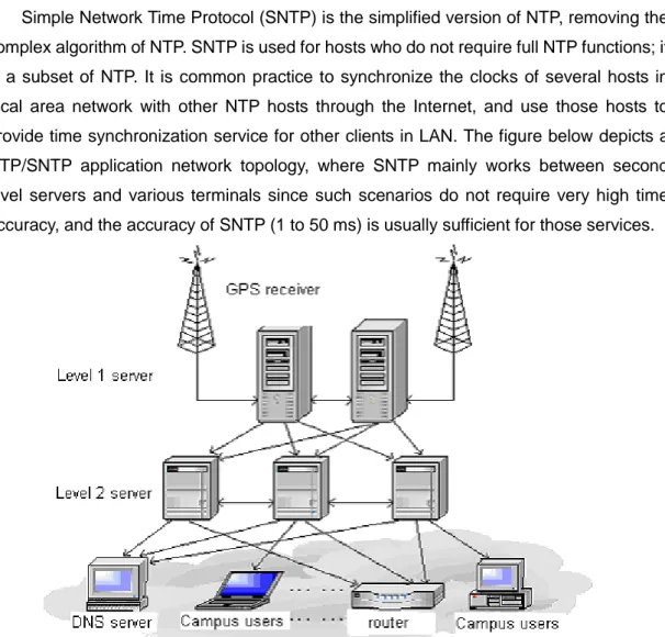
Simple Network Time Protocol (SNTP) is the simplified version of NTP, removing the complex algorithm of NTP. SNTP is used for hosts who do not require full NTP functions; it is a subset of NTP. It is common practice to synchronize the clocks of several hosts in local area network with other NTP hosts through the Internet, and use those hosts to provide time synchronization service for other clients in LAN. The figure below depicts a NTP/SNTP application network topology, where SNTP mainly works between second level servers and various terminals since such scenarios do not require very high time accuracy, and the accuracy of SNTP (1 to 50 ms) is usually sufficient for those services.
Network Time Management Configuration Chapter 1 SNTP Configuration
Switch implements SNTPv4 and supports SNTP client unicast as described in RFC2030; SNTP client multicast and unicast are not supported, nor is the SNTP server function.
1.2 Typical Examples of SNTP Configuration
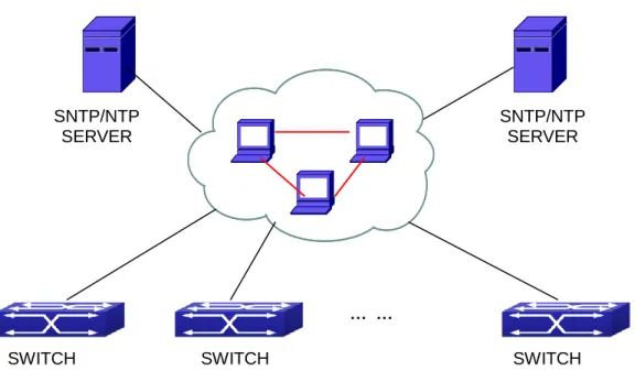
Fig 1-2 Typical SNTP Configuration
All switches in the autonomous zone are required to perform time synchronization, which is done through two redundant SNTP/NTP servers. For time to be synchronized, the network must be properly configured. There should be reachable route between any switch and the two SNTP/NTP servers.
Example: Assume the IP addresses of the SNTP/NTP servers are 10.1.1.1 and 20.1.1.1, respectively, and SNTP/NTP server function (such as NTP master) is enabled, then configurations for any switch should like the following:
Switch#config Switch(config)#sntp server 10.1.1.1 SWITCH … … SWITCH SWITCH SNTP/NTP SERVER SNTP/NTP SERVER
Chapter 2 NTP Function Configuration
2.1 Introduction to NTP Function
The NTP (Network Time Protocol) synchronizes timekeeping spans WAN and LAN among distributed time servers and clients, it can get millisecond precision. The introduction of event, state, transmit function and action are defined in RFC-1305.
The purpose of using NTP is to keep consistent timekeeping among all clock-dependent devices within the network so that the devices can provide diverse applications based on the consistent time.
For a local system running NTP, its time can be synchronized by other reference sources and can be used as a reference source to synchronize other clocks, also can synchronize each other by transmit NTP packets.
2.2 NTP Function Configuration Task List
1. To enable NTP function
2. To configure NTP server function
3. To configure the max number of broadcast or multicast servers supported by the NTP client
4. To configure time zone
5. To configure NTP access control list 6. To configure NTP authentication
7. To specified some interface as NTP broadcast/multicast client interface 8. To configure some interface can’t receive NTP packets
9. Display information 10. Debug 1. To enable NTP function Command Explication Global Mode ntp enable
ntp disable To enable or disable NTP function.
2. To configure NTP server function
Network Time Management Configuration Chapter 2 NTP Function Configuration
Global Mode
ntp server {<ip-address> | <ipv6-address>} [version <version_no>] [key <key-id>]
no ntp server {<ip-address> | <ipv6-address>}
To enable the specified time server of time source.
3. To configure the max number of broadcast or multicast servers supported by the NTP client
Command Explication
Global Mode
ntp broadcast server count <number> no ntp broadcast server count
Set the max number of broadcast or multicast servers supported by the NTP client. The no operation will cancel the configuration and restore the default value.
4. To configure time zone
Command Explication
Global Mode
clock timezone WORD {add | subtract} <0-23> [<0-59>]
no clock timezone WORD
This command configures timezone in global mode, the no command deletes the configured timezone.
5. To configure NTP access control list
Command Explication
Global Mode
ntp access-group server <acl> no ntp access-group server < acl>
To configure NTP server access control list.
6. To configure NTP authentication
Command Explication
Global Mode
ntp authenticate
no ntp authenticate To enable NTP authentication function. ntp authentication-key <key-id> md5
<value>
no ntp authentication-key <key-id>
To configure authentication key for NTP authentication.
ntp trusted-key <key-id>
no ntp trusted-key <key-id> To configure trusted key.
7. To specified some interface as NTP broadcast/multicast client interface
Command Explication
vlan Configuration Mode
ntp broadcast client no ntp broadcast client
To configure specified interface to receive NTP broadcast packets.
ntp multicast client no ntp multicast client
To configure specified interface to receive NTP multicast packets.
ntp ipv6 multicast client no ntp ipv6 multicast client
To configure specified interface to receive IPv6 NTP multicast packets.
8. To configure some interface can’t receive NTP packets
Command Explication
vlan Configuration Mode
ntp disable
no ntp disable To disable the NTP function.
9. Display information
Command Explication
Admin Mode
show ntp status To display the state of time synchronize.
show ntp session [ <ip-address> | <ipv6-address> ]
To display the information of NTP session. 10. Debug Command Explication Admin Mode debug ntp authentication no debug ntp authentication
To enable debug switch of NTP authentication.
debug ntp packets [send | receive] no debug ntp packets [send | receive]
To enable debug switch of NTP packet information.
Network Time Management Configuration Chapter 2 NTP Function Configuration
debug ntp adjust no debug ntp adjust
To enable debug switch of time update information.
debug ntp sync no debug ntp sync
To enable debug switch of time synchronize information.
debug ntp events no debug ntp events
To enable debug switch of NTP event information.
2.3 Typical Examples of NTP Function
A client switch wanted to synchronize time with time server in network, there is two time server in network, the one is used as host, the other is used as standby, the connection and configuration as follows (Switch A and Switch B are the switch or route which support NTP server ):
The configuration of Switch C is as follows: (Switch A and Switch B may have the different command because of different companies, we not explain there, our switches are not support NTP server at present)
Switch C: Switch(config)#ntp enable Switch(config)#interface vlan 1 Switch(Config-if-Vlan1)#ip address 192.168.1.12 255.255.255.0 Switch(config)#interface vlan 2 Switch(Config-if-Vlan1)#ip address 192.168.2.12 255.255.255.0 Switch(config)#ntp server 192.168.1.11 Switch(config)#ntp server 192.168.2.11
2.4 NTP Function Troubleshooting
In configuration procedures, if there is error occurred, the system can give out the debug information.
The NTP function disables by default, the show command can be used to display current configuration. If the configuration is right please use debug every relative debugging command and display specific information in procedure, and the function is configured right or not, you can also use show command to display the NTP running information, any questions please send the recorded message to the technical service center.
Network Time Management Configuration Chapter 3 DNSv4/v6 Configuration
Chapter 3 DNSv4/v6 Configuration
3.1 Introduction to DNS
DNS (Domain Name System) is a distributed database used by TCP/IP applications to translate domain names into corresponding IPv4/IPv6 addresses. With DNS, you can use easy-to-remember and signification domain names in some applications and let the DNS server translate them into correct IPv4/IPv6 addresses.
There are two types of DNS services, static and dynamic, which supplement each other in application. Each time the DNS server receives a name query it checks its static DNS database first before looking up the dynamic DNS database. Some frequently used addresses can be put in the static DNS database, the reduction the searching time in the dynamic DNS database would increase efficiency. The static domain name resolution means setting up mappings between domain names and IPv4/IPv6 addresses. IPv4/IPv6 addresses of the corresponding domain names can be found in the static DNS database when you use some applications. Dynamic domain name resolution is implemented by querying the DNS server. A user program sends a name query to the resolver in the DNS client when users want to use some applications with domain name, the DNS resolver looks up the local domain name cache for a match. If a match is found, it sends the corresponding IPv4/IPv6 address back to the switch. If no match is found, it sends a query to a higher DNS server. This process continues until a result, whether success or failure, is returned.
The Domain Name System (DNS) is a hierarchical naming system for computers, services, or any resource participating in the Internet. It associates various information with domain names assigned to such participants. Most importantly, it translates humanly meaningful domain names to the numerical (binary) identifiers associated with networking equipment for the purpose of locating and addressing these devices world-wide. An often used analogy to explain the Domain Name System is that it serves as the "phone book" for the Internet by translating human-friendly computer hostnames into IP addresses.
The Domain Name System makes it possible to assign domain names to groups of Internet users in a meaningful way, independent of each user's physical location. Because of this, World-Wide Web (WWW) hyperlinks and Internet contact information can remain consistent and constant even if the current Internet routing arrangements change or the participant uses a mobile device. Internet domain names are easier to remember than IP addresses such as 208.77.188.166(IPv4) or 2001:db8:1f70::999:de8:7648:6e8 (IPv6). People take advantage of this when they recite meaningful URLs and e-mail addresses
without having to know how the machine will actually locate them.
The Domain Name System distributes the responsibility for assigning domain names and mapping them to Internet Protocol (IP) networks by designating authoritative name servers for each domain to keep track of their own changes, avoiding the need for a central register to be continually consulted and updated.
In general, the Domain Name System also stores other types of information, such as the list of mail servers that accept email for a given Internet domain. By providing a world-wide, distributed keyword-based redirection service, the Domain Name System is an essential component of the functionality of the Internet.
3.2 DNSv4/v6 Configuration Task List
1. To enable/disable DNS function 2. To configure/delete DNS server
3. To configure/delete domain name suffix
4. To delete the domain entry of specified address in dynamic cache 5. To enable DNS dynamic domain name resolution
6. Enable/disable DNS SERVER function
7. Configure the max number of client information in the switch queue 8. Configure the timeout value of caching the client information on the switch 9. Monitor and diagnosis of DNS function
1. To enable/disable DNS function
Command Explanation
Global Mode
ip domain-lookup no ip domain-lookup
To enable/disable DNS dynamic lookup function.
2.To configure/delete DNS server
Command Explanation
Global Mode
dns-server {<ip-address> | <ipv6-address>} [priority <value>] no dns-server {<ip-address> | <ipv6-address>}
To configure DNS server, the no form of this command deletes DNS server.
3.To configure/delete domain name suffix
Network Time Management Configuration Chapter 3 DNSv4/v6 Configuration
Global Mode
ip domain-list <WORD>
no ip domain-list <WORD> To configure/delete domain name suffix.
4. To delete the domain entry of specified address in dynamic cache
Command Explanation
Admin Mode
clear dynamic-host {<ip-address> | <ipv6-address> | all}
To delete the domain entry of specified address in dynamic cache.
5. To enable DNS dynamic domain name resolution
Command Explanation
Global Mode
dns lookup {ipv4 | ipv6} <hostname> To enable DNS dynamic domain name
resolution.
6. Enable/disable DNS SERVER function
Command Explanation
Global Mode
ip dns server
no ip dns server Enable/disable DNS SERVER function.
7. Configure the max number of client information in the switch queue
Command Explanation
Global Mode
ip dns server queue maximum <1-5000>
no ip dns server queue maximum
Configure the max number of client information in the switch queue.
8. Configure the timeout value of caching the client information on the switch
Command Explanation
Global Mode
ip dns server queue timeout <1-100> no ip dns server queue timeout
Configure the timeout value of caching the client information on the switch.
9. Monitor and diagnosis of DNS function
Command Explanation
show dns name-server To show the configured DNS server
information.
show dns domain-list To show the configured DNS domain
name suffix information.
show dns hosts To show the dynamic domain name
information of resolved by switch.
show dns config Display the configured global DNS
information on the switch.
show dns client Display the DNS Client information
maintained by the switch.
debug dns {all | packet [send | recv] | events | relay}
no debug dns {all | packet [send | recv] | events | relay}
To enable/disable DEBUG of DNS function.
3.3 Typical Examples of DNS
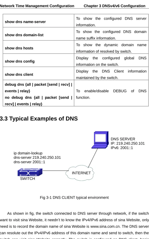
Fig 3-1 DNS CLIENT typical environment
As shown in fig, the switch connected to DNS server through network, if the switch want to visit sina Website, it needn’t to know the IPv4/IPv6 address of sina Website, only need is to record the domain name of sina Website is www.sina.com.cn. The DNS server can resolute out the IPv4/IPv6 address of this domain name and send to switch, then the switch can visit sina Website correctly. The switch is configured as DNS client, basic configurations are as below: first to enable DNS dynamic domain name resolution function on switch, and configure DNS server address, then with some kinds of tools such as PING, the switch can get corresponding IPv4/IPv6 address with dynamic domain name
DNS SERVER IP: 219.240.250.101 IPv6: 2001::1 ip domain-lookup dns-server 219.240.250.101 dns-server 2001::1 SWITCH INTERNET
Network Time Management Configuration Chapter 3 DNSv4/v6 Configuration
resolution function.
Fig 3-2 DNS SERVER typical environment
The figure above is an application of DNS SERVER. Under some circumstances, the client PC doesn’t know the real DNS SERVER, and points to the switch instead. The switch plays the role of a DNS SERVER in two steps: Enable the global DNS SERVER function, configure the IP address of the real DNS server. After the DNS SERVER function is globally enabled, the switch will look up its local cache when receiving a DNS request from a client PC. If there is a domain needed by the local client, it will directly answer the client’s request; otherwise, the switch will relay the request to the real DNS server, pass the reply from the DNS Server to the client and record the domain and its IP address for a faster lookup in the future.
Switch configuration for DNS CLIENT: Switch(config)# ip domain-lookup
Switch(config)# dns-server 219.240.250.101 Switch(config)# dns-server 2001::1
Switch#ping host www.sina.com.cn Switch#traceroute host www.sina.com.cn Switch#telnet host www.sina.com.cn
Switch configuration for DNS SERVER: Switch(config)# ip domain-lookup
Switch(config)# dns-server 219.240.250.101 Switch(config)# dns-server 2001::1
Switch(config)# ip dns server
3.4 DNS Troubleshooting
In configuring and using DNS, the DNS may fail due to reasons such as physical DNS SERVER IP:219.240.250.101 IPv6:2001::1 INTERNET SWITCH client
connection failure or wrong configurations. The user should ensure the following:
First make sure good condition of the TACACS+ server physical connection;
Second all interface and link protocols are in the UP state (use “show interface”
command);
Then please make sure that the DNS dynamic lookup function is enabled (use the “ip domain-lookup” command) before enabling the DNS CLIENT function. To use DNS SERVER function, please enable it (use the “ip dns server” command);
Finally ensure configured DNS server address (use “dns-server” command), and the
switch can ping DNS server;
If the DNS problems remain unsolved, please use debug DNS all and other debugging command and copy the DEBUG message within 3 minutes, send the recorded message to the technical service center of our company.
Network Time Management Configuration Chapter 4 Summer Time Configuration
Chapter 4 Summer Time Configuration
4.1 Introduction to Summer Time
Summer time is also called daylight saving time, it is a time system for saving energy sources. In summer the time is advanced 1 hour to keep early hours, reduce the lighting, so as to save electrolighting. The rule that adopt summer time is different in each country. At present, almost 110 countries implement summer time.
Compare with the standard time, usually set summer time 1 hour late, for example, when summer time is implementing, 10:00 am of the standard time is considered 11:00 am of summer time.
4.2 Summer Time Configuration Task Sequence
1. Configure absolute or recurrent time range of summer time
Command Explanation
Global Mode
clock summer-time <word> absolute <HH:MM> <YYYY.MM.DD> <HH:MM> <YYYY.MM.DD> [<offset>]
noclock summer-time
Set absolute time range of summer time, start and end summer time is configured with specified year.
clock summer-time <word> recurring <HH:MM> <MM.DD> <HH:MM> <MM.DD> [<offset>]
noclock summer-time
Set recurrent time range of summer time, every year the summer time begins from the start time and end at the end time.
clock summer-time <word> recurring <HH:MM> <week> <day> <month> <HH:MM> <week> <day> <month> [<offset>]
noclock summer-time
Set recurrent time range of summer time, every year the summer time begins from the start time and end at the end time.
4.3 Examples of Summer Time
Example1:
The configuration requirement in the following: The summer time from 23:00 on April 1th, 2012 to 00:00 on October 1th, 2012, clock offset as 1 hour, and summer time is named as 2012.
Configuration procedure is as follows:
Switch(config)# clock summer-time 2012 absolute 23:00 2012.4.1 00:00 2012.10.1
Example2:
The configuration requirement in the following: The summer time from 23:00 on the first Saturday of April to 00:00 on the last Sunday of October year after year, clock offset as 2 hours, and summer time is named as time_travel.
Configuration procedure is as follows:
Switch(config)#clock summer-time time_travel recurring 23:00 first sat apr 00:00 last sun oct 120
4.4 Summer Time Troubleshooting
If there is any problem happens when using summer time, please check whether the problem is caused by the following reasons:
Check whether command mode in global mode