National Renewable Energy Laboratory
Innovation for Our Energy Future
A national laboratory of the U.S. Department of Energy Office of Energy Efficiency & Renewable Energy
NREL is operated by Midwest Research Institute ● Battelle Contract No. DE-AC36-99-GO10337
A New Empirical
Relationship between Thrust
Coefficient and Induction
Factor for the Turbulent
Windmill State
Marshall L. Buhl, Jr.
Technical Report
NREL/TP-500-36834 August 2005
A New Empirical
Relationship between Thrust
Coefficient and Induction
Factor for the Turbulent
Windmill State
Marshall L. Buhl, Jr.
Prepared under Task No(s). WER5.3316
Technical Report
NREL/TP-500-36834 August 2005
National Renewable Energy Laboratory 1617 Cole Boulevard, Golden, Colorado 80401-3393 303-275-3000 • www.nrel.gov
Operated for the U.S. Department of Energy Office of Energy Efficiency and Renewable Energy by Midwest Research Institute • Battelle
NOTICE
This report was prepared as an account of work sponsored by an agency of the United States government. Neither the United States government nor any agency thereof, nor any of their employees, makes any warranty, express or implied, or assumes any legal liability or responsibility for the accuracy, completeness, or usefulness of any information, apparatus, product, or process disclosed, or represents that its use would not infringe privately owned rights. Reference herein to any specific commercial product, process, or service by trade name, trademark, manufacturer, or otherwise does not necessarily constitute or imply its endorsement, recommendation, or favoring by the United States government or any agency thereof. The views and opinions of authors expressed herein do not necessarily state or reflect those of the United States government or any agency thereof.
Available electronically at http://www.osti.gov/bridge
Available for a processing fee to U.S. Department of Energy and its contractors, in paper, from:
U.S. Department of Energy
Office of Scientific and Technical Information P.O. Box 62
Oak Ridge, TN 37831-0062 phone: 865.576.8401 fax: 865.576.5728
email: mailto:[email protected] Available for sale to the public, in paper, from:
U.S. Department of Commerce
National Technical Information Service 5285 Port Royal Road
Springfield, VA 22161 phone: 800.553.6847 fax: 703.605.6900
email: [email protected]
online ordering: http://www.ntis.gov/ordering.htm
Contents
Abstract ...1
The Problem...2
Derivation...4
Conclusions...7
References ...7
Figures
Figure 1. Classical C
r– a curve when losses are ignored...2
Figure 2. Classical C
ra curve and Glauert’s empirical relationship
when losses are ignored ...3
Figure 3. Classical C
r– a curve with losses (
F
= 0.9) included and Glauert’s
empirical relationship...4
Figure 4. Classical C
r– a curve and Glauert’s empirical relationship
when losses (
F
= 0.9) are included in both equations ...5
Figure 5. Classical C
r– a curve and the newly derived empirical relationship
when losses (
F
= 0.9) are included in both equations ...6
Abstract
Wind turbines sometimes experience the turbulent windmill state during startup or shutdown. This rarely happens during normal operation, so it has little effect on power curves or energy production. However, for completeness we need to be able to model situations where the axial induction factor exceeds 0.5. Classical momentum theory, which shows a relationship between the thrust coefficient and the axial induction factor, is not valid in this region. Glauert plotted some experimental data taken by Lock in the 1920s against this parabolic relationship and found very poor agreement for operation in this high-induction state. He proposed a new empirical re-lationship to fit the experimental data. Unfortunately, the new empirical curve does not account for tip or hub losses. Others have proposed multiplying the axial induction factor by the loss factor to correct the curve, but this still leaves a mathematical no-man’s-land between the classi-cal curve and the modified version of Glauert’s empiriclassi-cal curve. The purpose of this paper is to document the derivation of a new curve that accounts for tip and hub losses and eliminates the numerical problems of the previous approaches.
The Problem
A review of several textbooks on wind turbine theory revealed that no one has addressed the nu-merical discontinuity problem associated with the Glauert empirical relationship (Lock et al. [1926], Glauert [1926]) between thrust coefficient and axial induction when tip losses are applied to the turbulent windmill state. (See Burton et al. [2001], Eggleston and Stoddard [1987],
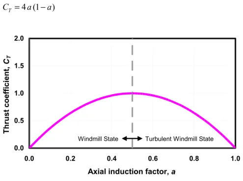
Manwell et al. [2002], and Spera [1994] for discussions of classical momentum theory and the Glauert empirical equation.) Eggleston and Stoddard discussed the classical thrust coefficient, CT, versus induction factor, a, curve, which is shown in Equation 1 and Figure 1. The dotted portion of the curve above the induction value of 0.5 represents the portion of the curve that vio-lates the basic assumptions used to derive it.
4 (1 )
= −
T
C a a (1)
0.0 0.5 1.0 1.5 2.0
0.0 0.2 0.4 0.6 0.8 1.0
Axial induction factor, a
T
h
ru
st co
efficient,
CT
Turbulent Windmill State Windmill State
Figure 1. Classical CT – a curve when losses are ignored
Glauert fit a parabola to some experimental data of rotors operating in the turbulent windmill state. This parabola touched the classical momentum curve at a = 0.4 and went through 2.0 for a = 1.0. The curve, as documented by Eggleston and Stoddard, is given by the formula shown in Equation 2 after solving for CT. Burton et al. used a line that is tangential to the theory parabola to fit the data. The choice of the intersection determines the slope and fit of the curve. The Burton textbook proposed an induction value of 0.326 for the intersection of the two curves. The book also reported that Wilson and Lissaman chose a value of 0.368. A plot of the three empiri-cal curves with the classiempiri-cal momentum theory curve and the test data is shown in Figure 2. We digitized the test data from Figure 3.16 of Burton’s book. There is a large spread in the data, which indicates that the thrust coefficient is not a simple function of induction factor in the tur-bulent windmill state.
2
0.0203 ( 0.143) 0.889
0.6427 T
a
C = − − − (2)
0.0 0.5 1.0 1.5 2.0
0.0 0.2 0.4 0.6 0.8 1.0 Axial induction factor, a
Thrus
t coef
fi
ci
ent
,
CT
Theory Lock Data Glauert Burton Wilson
Turbulent Windmill State Windmill State
Figure 2. Classical CT – a curve and Glauert’s empirical relationship when losses are ignored
A numerical problem arises when one applies the tip/hub loss correction factor, F, to the classi-cal momentum balance equation (see Equation 3).
4 (1
= −
T
C a F a) (3)
Plotting this modified equation shows a gap between the momentum curve and Glauert’s curve (Figure 3) for a loss factor of 0.9. This gap creates a discontinuity when a computer is used to iterate for the induction factor. Eggleston and Stoddard modified Equation 2 to multiply the in-duction factor by the loss factor. This modification to the Glauert empirical relationship lowers the entire curve, but not enough to eliminate all of the discontinuity (see Figure 4).
Derivation
For the turbulent windmill state we need a curve that tangentially touches the classical momen-tum curve and thereby eliminates the numerical no-man’s-land. The data Glauert used exhibit a very wide scatter. The resulting equation was probably chosen to resolve the numerical problem rather than to obtain a good fit for the data. (See Eggleston and Stoddard, p. 22 for a plot of the data.) Therefore, choosing a parabolic curve that has the same value and slope for a = 0.4 as the classical equation with losses, and that goes through 2.0 at a = 1.0, should be somewhat reason-able. We can do this with simple algebra.
The derivative of Equation 1 (assuming fixed F for a given iteration) gives
4 (1 2 )
= −
T
dC
F a
da . (4)
At a = 0.4, Equations 3 and 4 become 0.96
= T
C F (5)
and
0.8
= T
dC
F
da . (6)
0.0 0.5 1.0 1.5 2.0
0.0 0.2 0.4 0.6 0.8 1.0 Axial induction factor, a
T
h
rust
co
ef
fi
ci
en
t,
CT
Turbulent Windmill Windmill
Gap
Figure 3. Classical CT – a curve with losses (F = 0.9) included and Glauert’s empirical relationship
0.0 0.5 1.0 1.5 2.0
0.0 0.2 0.4 0.6 0.8 1.0 Axial induction factor, a
T h rust coef fi ci ent , C T
Turbulent Windmill State Windmill State
Gap
Figure 4. Classical CT – a curve and Glauert’s empirical relationship when losses (F = 0.9) are included in both equations
A general quadratic equation for thrust coefficient is
2
0 1 2
= + +
T
C b b a b a , (7)
where b0, b1, and b2, must be selected to satisfy the conditions stated above. The slope of this equation is
1 2 2
= + T dC b b da a 2 . (8) At an induction factor of 0.4, Equations 7 and 8 become
0 0.4 1 0.16
= + +
T
C b b b , (9)
and 1 0.8 = + T dC b
da b2
F
F
. (10) When we equate Equations 5 and 9, we get
0+0.4 1+0.16 2 =0.96
b b b . (11)
Equating Equations 6 and 10 yields
1+0.8 2 =0.8
b b . (12)
At an induction factor of 1, we want our quadratic to be equal to 2, so
0 1 2 2
= + + = T
C b b b . (13)
If we subtract Equation 11 from Equation 13, we get
1 2
0.6b +0.84b = −2 0.96F . (14)
Next, if we subtract 0.6*Equation 12 from Equation 14 and solve for b2 we get
2
50 4 9
= −
b F. (15)
Solving Equation 12 for b1 yields
1 2
4 4
4
5 9
= − = −
b F b F 0, (16)
And solving Equation 13 for b0 yields
0 1 2
8 2
9
= − − =
b b b . (17)
We now have an equation that produces a curve that just touches the classical momentum equa-tion at a = 0.4 and goes through 2 at a = 1 (see Figure 5).
2
8 40 50
4
9 9 9
⎛ ⎞ ⎛
= +⎜ − ⎟ +⎜ −
⎝ ⎠ ⎝
T
C F a 4F⎞⎟
⎠a . (18)
0.0 0.5 1.0 1.5 2.0
0.0 0.2 0.4 0.6 0.8 1.0 Axial induction factor, a
T h rust co ef fi ci en t, CT Turbulent Windmill Windmill No Gap
Figure 5. Classical CT – a curve and the newly derived empirical relationship when losses (F = 0.9) are included in both equations
Conclusions
We have shown that previous relationships between the thrust coefficient and the induction fac-tor in the turbulent windmill state have produced numerical discontinuities in the induction itera-tion with tip or hub losses. We derived a new equaitera-tion that solves the discontinuity problem and provides a reasonable approximation to the experimental data. Although it is not a perfect fit to the data, it is probably as good as the original Glauert equation. This is the best-known method to compute the induction in the turbulent windmill state. However, it does not account for the spread in the data, which is a problem that needs further investigation.
References
Burton, T.; Sharpe, D.; Jenkins, N.; Bossanyi, E.. (2001). Wind Energy Handbook. West Sussex, England: John Wiley & Sons, Ltd.; pp. 66–68.
Eggleston, D.M.; Stoddard, F.S. (1987). Wind Turbine Engineering Design. New York, NY: Van Nostrand Reinhold; pp. 30–35, 58.
Glauert, H. (1926). The Analysis of Experimental Results in the Windmill Brake and Vortex Ring States of an Airscrew, Rept. 1026. Aeronautical Research Committee Reports and Memoranda, London: Her Majesty’s Stationery Office.
Lock, C.N.H.; Batemen, H.; Townsend, H.C.H. (1926). An Extension of the Vortex Theory of Airscrews with Applications to Airscrews of Small Pitch, Including Experimental Results. No. 1014. Aeronautical Research Committee Reports and Memoranda, London: Her Majesty’s Stationery Office.
Manwell, J.F.; McGowan, J.G.; Rogers, A.L. (2002). Wind Energy Explained. West Sussex, England: John Wiley & Sons, Ltd.; pp. 120–121.
Wilson, R.E. (1994). “Aerodynamic Behavior of Wind Turbines,” Chapter 5. Spera, D.A., ed. Wind Turbine Technology. New York, NY: The American Society of Mechanical Engineers; pp. 231–232.
F1147-E(12/2004)
REPORT DOCUMENTATION PAGE OMB No. 0704-0188Form Approved
The public reporting burden for this collection of information is estimated to average 1 hour per response, including the time for reviewing instructions, searching existing data sources, gathering and maintaining the data needed, and completing and reviewing the collection of information. Send comments regarding this burden estimate or any other aspect of this collection of information, including suggestions for reducing the burden, to Department of Defense, Executive Services and Communications Directorate (0704-0188). Respondents should be aware that notwithstanding any other provision of law, no person shall be subject to any penalty for failing to comply with a collection of information if it does not display a currently valid OMB control number.
PLEASE DO NOT RETURN YOUR FORM TO THE ABOVE ORGANIZATION. 1. REPORT DATE (DD-MM-YYYY)
August 2005
2. REPORT TYPE Technical Report
3. DATES COVERED (From - To)
5a. CONTRACT NUMBER
DE-AC36-99-GO10337 5b. GRANT NUMBER
4. TITLE AND SUBTITLE
A New Empirical Relationship between Thrust Coefficient and Induction Factor for the Turbulent Windmill State
5c. PROGRAM ELEMENT NUMBER
5d. PROJECT NUMBER NREL/TP-500-36834 5e. TASK NUMBER
WER43305 6. AUTHOR(S)
Marshall L. Buhl, Jr.
5f. WORK UNIT NUMBER
7. PERFORMING ORGANIZATION NAME(S) AND ADDRESS(ES) National Renewable Energy Laboratory
1617 Cole Blvd.
Golden, CO 80401-3393
8. PERFORMING ORGANIZATION REPORT NUMBER
NREL/TP-500-36834
10. SPONSOR/MONITOR'S ACRONYM(S) NREL
9. SPONSORING/MONITORING AGENCY NAME(S) AND ADDRESS(ES)
11. SPONSORING/MONITORING AGENCY REPORT NUMBER
12. DISTRIBUTION AVAILABILITY STATEMENT National Technical Information Service U.S. Department of Commerce
5285 Port Royal Road Springfield, VA 22161 13. SUPPLEMENTARY NOTES
14. ABSTRACT (Maximum 200 Words)
Classical momentum theory shows a relationship between the thrust coefficient and the axial induction factor. Glauert plotted some experimental results against this parabolic relationship and found very poor agreement for operation in the turbulent windmill state. He proposed a new empirical relationship to fit the experimental data. Unfortunately, the new empirical curve does not account for tip or hub losses. Others have proposed that one simply multiply the axial induction factor but the loss factor to correct the curve, but this still leaves a mathematical no man’s land between the classical curve and the modified version of Glauert’s empirical curve. This paper derives a new curve that accounts for tip and hub losses and eliminates the discontinuity.
15. SUBJECT TERMS
momentum theory; Glauert; induction; wind turbine; turbulent windmill state
16. SECURITY CLASSIFICATION OF: 19a. NAME OF RESPONSIBLE PERSON
a. REPORT
Unclassified
b. ABSTRACT
Unclassified
c. THIS PAGE
Unclassified 17. LIMITATION OF ABSTRACT UL 18. NUMBER OF PAGES
19b. TELEPHONE NUMBER (Include area code)
Standard Form 298 (Rev. 8/98)