Conservation of Fuel
and Energy - Buildings
other than Dwellings
Te c h n i c a l
G u i d a n c e
D o c u m e n t
L
B u i l d i n g
Re g u l a t i o n s
Building Regulations 2008
Te c h n i c a l G u i d a n c e D o c u m e n t L
Conservation of Fuel and Energy - B u i l d i n g s
o t h e r t h a n D we l l i n g s
BAILE ÁTHA CLIATH
ARNA FHOILSIÚ AG OIFIG AN TSOLÁTHAIR LE CEANNACH dIREACH ON
OIFIG dHÍOLTA FOILSEACHÁN RIALTAIS,
TEACH SUN ALLIANCE, SRÁId THEACH LAIGHEAN, BAILE ÁTHA CLIATH 2, NO TRId AN BPOST O
FOILSEACHÁIN RIALTAIS, AN RANNÓG POST-TRÁCHTA,
AONAd 20 PÁIRC MIONdÍOLA COIS LOCHA, CLÁR CHLAINNE MHUIRIS, CONTAE MHAIGH EO
(TEIL: 01-6476834/37 NO 1890 213434; FAx: 01-6476843 NO 094-9378964 ) NO TRI AON dIOLTOIR LEABHAR.
________________________
dUBLIN
PUBLISHEd BY THE STATIONERY OFFICE TO BE PURCHASEd dIRECTLY FROM THE GOVERNMENT PUBLICATIONS SALE OFFICE
SUN ALLIANCE HOUSE, MOLESWORTH STREET, dUBLIN 2, OR BY MAIL ORdER FROM
GOVERNMENT PUBLICATIONS, POSTAL TRAdE SECTION, UNIT 20 LAKESIdE RETAIL PARK, CLAREMORRIS, CO. MAYO (TEL: 01-6476834/37 OR 1890 213434; FAx: 01-6476843 OR 094 9378964) OR THROUGH ANY BOOKSELLER.
_______________________
Contents
Page
Introduction 5
Transitional Arrangements 5
The Guidance 5
Existing Buildings 5
Technical Specifications 5
Materials and Workmanship 6
Interpretation 6
Building Regulations - The Requirement 7 Section 0: General Guidance
0.1 Application of the Regulations 9 0.2 Technical Risks and Precautions 11
0.2.1 General 11
0.2.2 Fire Safety 11
0.2.3 Ventilation 11
0.3 Thermal Conductivity and Thermal Transmittance 11
0.4 Dimensions 12
0.5 Definitions 12
0.6 Application to Buildings of Architectural or Historical Interest 13
Section 1: Buildings other than Dwellings
1.1 Limitation of Primary Energy Use and C02emissions for New Buildings other
than Dwellings 15
1.2 Heat Loss and Gain through the Building Fabric 16 1.2.1 Heat Loss - General 16 1.2.2 Overall Heat Loss Method 16 1.2.3 Elemental Heat Loss Method 17
1.2.4 Thermal Bridging 18
1.2.5 Air Infiltration 21
1.2.6 Avoiding Solar Overheating 21
1.3 Building Services 23
1.3.1 Heating Plant Efficiency 23 1.3.2 Controls for Space Heating and Hot Water Supply
Systems 23
1.3.3 Air Conditioning and Mechanical Ventilation (ACMV) 23 1.3.4 Insulation of Storage Vessels, Pipes and Ducts 24 1.3.5 Artificial Lighting 24
Appendices
A Calculation of U-values 27
B Fabric Insulation: Additional Guidance (including Tables of U-Values)
for Common Constructions 35 C Reference Values for Calculation of Maximum Permitted Energy
Performance Coefficient (MPEPC) and Maximum Permitted Carbon
Performance Coefficient (MPCPC) 57
D Thermal Bridging 60
E Avoidance of Solar Overheating 62
Introduction
This document has been published by the Minister for the Environment, Heritage and Local Government under article 7 of the Building Regulations 1997.
It provides guidance in relation to Part L of the Second Schedule to the Regulations as inserted by Building Regulations (Part L Amendment) Regulations 2008 (S.I. No. 259 of 2008). The guidance in this document applies to buildings other than dwellings.
These Regulations (and this document) partly transpose the EU Energy Performance of Buildings Directive - EPBD (2002/91/EC of 16 December 2002).
The document should be read in conjunction with the Building Regulations 1997-2005 and other documents published under these Regulations.
In general, Building Regulations apply to the construction of new buildings and to extensions and material alterations to existing buildings. In addition, certain parts of the Regulations apply to existing buildings where a material change of use takes place. (Otherwise, Building Regulations do not apply to buildings constructed prior to 1 June 1992).
Transitional Arrangements
In general, this document applies to works, or buildings in which a material alteration or change of use takes place, where the work, material alteration or the change of use commences or takes place, as the case may be, on or after 10 July 2008.
Technical Guidance Document L - Conservation of Fuel and Energy (May 2006 edition) ceases to have effect from 9 July 2008.
However, this document may continue to be used in the case of buildings:
- where the work, material alteration or the change of use commences or takes place, as the case may be, on or before 30 June 2008, or
- where planning approval or permission has been applied for on or before 30 June 2008, and substantial work has been completed by 30 June 2010.
“Substantial work has been completed” means that the structure of the external walls has been erected.
The Guidance
The materials, methods of construction, standards and other specifications (including technical specifications)
which are referred to in this document are those which are likely to be suitable for the purposes of the Building Regulations (as amended). Where works are carried out in accordance with the guidance in this document, this will, prima facie, indicate compliance with Part L of the Second Schedule to the Building Regulations.
However, the adoption of an approach other than that outlined in the guidance is not precluded provided that the relevant requirements of the Regulations are complied with. Those involved in the design and construction of a building may be required by the relevant building control authority to provide such evidence as is necessary to establish that the requirements of the Regulations are being complied with.
Existing Buildings
In the case of material alterations or change of use of existing buildings, the adoption without modification of the guidance in this document may not, in all circumstances, be appropriate. In particular, the adherence to guidance, including codes, standards or technical specifications intended for application to new work may be unduly restrictive or impracticable.
Buildings of architectural or historical interest are especially likely to give rise to such circumstances. In these situations, alternative approaches based on the principles contained in the document may be more relevant and should be considered.
Technical Specifications
Building Regulations are made for specific purposes, e.g. to provide, in relation to buildings, for the health, safety and welfare of persons, the conservation of energy, and access for people with disabilities.
Technical specifications (including harmonised European Standards, European Technical Approvals, National Standards and Agrement Certificates) are relevant to the extent that they relate to these considerations.
Any reference to a technical specification is a reference to so much of the specification as is relevant in the context in which it arises. Technical specification may also address other aspects not covered by the Regulations.
A reference to a technical specification is to the latest edition (including any amendments, supplements or addenda) current at the date of publication of this Technical Guidance Document. However, if this version of the technical specification is subsequently revised or updated by the issuing body, the new version may be used as a source of guidance provided that it continues to address the relevant requirements of the Regulations.
Building Regulations 2008
Technical Guidance Document L
Conservation of Fuel and Energy -
Buildings other than Dwellings
Materials and Workmanship
Under Part D of the Second Schedule to the Building Regulations, building work to which the Regulations apply must be carried out with proper materials and in a workmanlike manner. Guidance in relation to compliance with Part D is contained in Technical Guidance Document D.
Interpretation
In this document, a reference to a section, paragraph, appendix or diagram is, unless otherwise stated, a reference to a section, paragraph, appendix or diagram, as the case may be, of this document. A reference to another Technical Guidance Document is a reference to the latest edition of a document published by the Department of the Environment, Heritage and Local Government under article 7 of the Building Regulations 1997.
Diagrams are used in this document to illustrate particular aspects of construction - they may not show all the details of construction.
Conservation of Fuel and Energy
Building Regulations - The Requirement
The requirements regarding conservation of fuel and energy are laid out in Part L of the Second Schedule to the Building Regulations 1997 (S.I. No. 497 of 1997) as amended by the Building Regulations (Part L Amendment) Regulations 2008 (S.I. No. 259 of 2008).
The Second Schedule is amended to read, in relation to buildings other than dwellings, as follows:
Conservation of Fuel L1 A building shall be designed and constructed so as to ensure that the energy and Energy performance of the building is such as to limit the amount of energy required
for the operation of the building and the amount of CO2emissions associated
with this energy use insofar as is reasonably practicable.
Buildings other L4 For buildings other than dwellings, the requirements of L1 shall be met by: than dwellings
(a) providing that the energy performance of the new building is such as to limit the calculated primary energy consumption and related CO2
emissions insofar as is reasonably practicable, when both energy consumption and CO2 emissions are calculated using the Non-domestic
Energy Assessment Procedure (NEAP) published by Sustainable Energy Ireland;
(b) limiting the heat loss and, where appropriate, maximising the heat gains through the fabric of the building;
(c) providing energy efficient space and water heating services including adequate control of these services;
(d) ensuring that the building is appropriately designed to limit need for cooling and, where air-conditioning or mechanical ventilation is installed, that installed systems are energy efficient, appropriately sized and adequately controlled;
(e) limiting the heat loss from pipes, ducts and vessels used for the transport or storage of heated water or air;
(f) limiting the heat gains by chilled water and refrigerant vessels, and by pipes and ducts that serve air conditioning systems;
(g) providing energy efficient artificial lighting systems (other than emergency lighting, display lighting or specialist process lighting) and adequate control of these systems.
Section 0:
-0.1 APPLICATIOn OF ThE
REGULATIOnS
0.1.1 The aim of Part L of the First Schedule to the Building Regulations is to limit the use of fossil fuel energy and related CO2 emissions arising from
the operation of buildings, while ensuring that occupants can achieve adequate levels of lighting and thermal comfort. Buildings should be designed and constructed to achieve this aim as far as is practicable.
0.1.2 For new buildings other than dwellings, the key issues to be addressed in order to ensure compliance are:
a. to provide that the calculated primary energy consumption associated with the operation of the building and the related CO2 emissions as
described in Section 1.1 do not exceed a target value specified in this document;
b. to limit the heat loss and, where appropriate, maximise the heat gains through the fabric of the building;
c. to provide energy efficient space and water heating services including adequate control of these services;
d. to ensure that the building is appropriately designed to limit the need for cooling and, where air-conditioning or mechanical ventilation is installed, that installed systems are energy efficient, appropriately sized and adequately controlled;
e. to limit the heat loss from pipes, ducts and vessels used for the transport or storage of heated water or air;
f. to limit the heat gains by chilled water and refrigerant vessels, and by pipes and ducts that serve air conditioning systems;
g. to provide energy efficient artificial lighting systems (other than emergency lighting, display lighting or specialist process lighting) and adequate control of these systems.
The principal aims of Part L of the Building Regulations are to limit primary energy consumption and associated CO2 emissions. Meeting the
performance levels specified for items b to g will not necessarily mean that the level specified for primary energy consumption and related CO2 emissions
(item a) will be met. It is likely that one or more of the performance levels specified, for items b to g, will need to be exceeded to achieve this.
0.1.3 Where a dwelling has an attached room or space that is to be used for commercial purposes (e.g. workshop, surgery, consulting room or office), such room or space should be treated as part of the dwelling if the commercial part could revert to domestic use on a change of ownership, e.g. where there is direct access between the commercial space and the living accommodation, both are contained within the same thermal envelope and the living accommodation occupies a substantial proportion of the total area of the building.
0.1.4 The guidance given in this Technical Guidance Document is generally applicable. However, where the works are limited in nature and not likely to greatly affect overall energy consumption over the building’s life, compliance may be achieved without implementation of this guidance or equivalent measures in detail. In particular,
- For small extensions, not exceeding 6.5m2 in
floor area, reasonable provision can be considered to have been made if the new construction is similar to the existing construction.
- Unheated ancillary areas such as porches, garages and the like do not require specific provisions in order to satisfy this Part of the Building Regulations.
- Where the area treated by an Air Conditioning and Mechanical Ventilation (ACMV) system is less than 200 m2, the
guidance in relation to ACMV systems need not be applied.
- Where the total design lighting load does not exceed 1000 W, the guidance in relation to the efficiency and control of artificial lighting need not be applied.
0.1.5 The guidance given in this Technical Guidance Document applies to buildings designed to be heated to temperatures appropriate for human occupancy. Less demanding standards could represent reasonable provision in those buildings or parts of buildings with a low level of heating or where heating provision is not intended. Low level of heating is considered to be where there is an installed heating capacity of less than 10W/m2.
Where the occupancy level or level of heating required when in use cannot be established at construction stage, the building should be treated as fully heated and the provisions of Part L applied accordingly. It should be noted that the provisions of Part L apply where a material change of use occurs and such a change of use may require specific construction measures to comply with Part L. These measures may prove more costly than if carried out at the time of initial construction.
0.1.6 An attached conservatory-style sunspace or the like should generally be treated as an integral part of the building to which it is attached. However, where
- thermally separated from the adjacent spaces within the building by walls, doors and other opaque elements which have U-values not more than 10% greater than corresponding exposed elements, and
- unheated or, if providing with a heating facility, having provision for automatic temperature and on-off control independent of the heating provision in the main building,
it may be excluded from the assessment of the building for the purposes of asessing compliance with the provisions of Part L. In this case, the building may be assessed separately for compliance. The attached sunspace should be treated as an unheated space for the purposes of this assessment and should also be assessed separately as if it were an extension to an existing building (see Paragraph 1.2.3.3 below).
0.1.7 In large complex buildings it may be sensible to consider the provisions for conservation of fuel and energy separately for different parts of the
building in order to establish the measures appropriate to each part.
0.1.8The Regulations apply to all works to existing buildings that are covered by the requirements of the Building Regulations, including extensions, material alterations, material changes of use and window and door replacement. In carrying out this work, the aim should be to limit energy requirements for the operation of the building and associated CO2
emissions as far as practicable as required by Regulation L1.
The key issues to be addressed are:
(a) limiting the heat loss and, where appropriate, maximising the heat gains through the fabric of the building;
(b) providing energy efficient space and water heating services including adequate control of these services;
(c) ensuring that the building is appropriately designed to limit need for cooling and, where air-conditioning or mechanical ventilation is installed, that installed systems are energy efficient, appropriately sized and adequately controlled;
(d) limiting the heat loss from pipes, ducts and vessels used for the transport or storage of heated water or air;
(e) limiting the heat gains by chilled water and refrigerant vessels, and by pipes and ducts that serve air conditioning systems;
(f) providing energy efficient artificial lighting systems (other than emergency lighting, display lighting or specialist process lighting) and adequate control of these systems.
0.2 TEChnICAL RISkS AnD
PRECAUTIOnS
General
0.2.1 The incorporation of additional thickness of thermal insulation and other energy conservation measures can result in changes in traditional construction practice. Care should be taken in design and construction to ensure that these changes do not increase the risk of certain types of problems, such as rain penetration and condensation.
Some guidance on avoiding such increased risk is given in Appendix B of this document. General guidance on avoiding risks that may arise is also contained in the publication “Thermal insulation: avoiding risks; Building Research Establishment (Ref BR 262)”.
Guidance in relation to particular issues and methods of construction will be found in relevant standards.
Fire Safety
0.2.2 Part B of the Second Schedule to the Building Regulations prescribes fire safety requirements. In designing and constructing buildings to comply with Part L, these requirements must be met and the guidance in relation to fire safety in TGD B should be fully taken into account. In particular, it is important to ensure that windows, which provide secondary means of escape in accordance with Section 1.5 of TGD B, comply with the dimensional and other guidance for such windows set out in paragraph 1.5.6 of TGD B.
Ventilation
0.2.3 Part F of the Second Schedule to the Building Regulations prescribes ventilation requirements both to meet the needs of the occupants of the building and to prevent excessive condensation in roofs and roofspaces. A key aim of the provisions in relation to the ventilation of occupied spaces is to minimize the risk of condensation, mould growth or other indoor air quality problems. Technical Guidance Document F provides guidance in relation to ventilation of buildings.
Part J of the Second Schedule to the Building Regulations prescribes requirements in relation to the supply of air for combustion appliances, including open-flued appliances which draw air from the room or space in which they are situated. Technical Guidance Document J provides guidance in this regard.
0.3 ThERMAL COnDUCTIVITy AnD
ThERMAL TRAnSMITTAnCE
0.3.1 Thermal conductivity (λ-value) relates to a
material or substance, and is a measure of the rate at which heat passes through a uniform slab of unit thickness of that material or substance, when unit temperature difference is maintained between its faces. It is expressed in units of Watts per metre per degree (W/mK).
0.3.2 For the purpose of showing compliance with this Part of the Building Regulations, design λ-values
based on manufacturers declared values should be used. For thermally homogeneous materials declared and design values should be determined in accordance with I.S. EN ISO 10456: 1997. Design values for masonry materials should be determined in accordance with I.S. EN 1745: 2002. For insulation materials, values determined in accordance with the appropriate harmonized European standard should be used. Certified λ-values for foamed insulant
materials should take account of the blowing agent actually used. The use of HCFC for this purpose is no longer permitted.
For products or components for which no appropriate standard exists, measured values, certified by an approved body or certified laboratory (see TGD D), should be used.
0.3.3 Table A1 and A2 of Appendix A contains λ
-values for some common building materials and insulation materials. These are primarily based on data contained in I.S. EN 12524: 2000 or in CIBSE Guide A, Section A3. The values provide a general indication of the thermal conductivity that may be expected for these materials. In the absence of declared values, design values or certified measured values as outlined in paragraph 0.3.2, values of thermal conductivity given in Table A1 may be used. However, values for specific products may differ from these illustrative values. Indicative λ-values for
thermal insulation materials are given Table A2. These may be used at early design stage for the purpose of assessing likely compliance with this Part of the Regulations. However, compliance should be verified using thermal conductivity values for these materials derived as outlined in Paragraph 0.3.2 above.
0.3.4 Thermal transmittance (U-value) relates to a building component or structure, and is a measure of the rate at which heat passes through that component or structure when unit temperature difference is maintained between the ambient air temperatures on each side. It is expressed in units of Watts per square metre per degree of air temperature difference (W/m2K).
0.3.5 Thermal transmittance values (U-values) relevant to this Part of the Regulations are those relating to elements exposed directly or indirectly to the outside air. This includes floors directly in contact with the ground, suspended ground floors incorporating ventilated or unventilated voids, and elements exposed indirectly via unheated spaces. The U-value takes account of the effect of the ground, voids and unheated spaces on the rate of heat loss, where appropriate. Heat loss through elements that separate premises that can reasonably be assumed to be heated, is considered to be negligible. Such elements do not need to meet any particular U-value nor should they be taken into account in calculation of CO2emissions or overall transmission heat loss.
0.3.6 A range of methods exists for calculating U-values of building elements. Methods of calculation are outlined in Appendix A, together with examples of their use. Alternatively U-values may be based on certified measured values. Measurements of thermal transmission properties of building components generally should be made in accordance with I.S. EN ISO 8990: 1997, or, in the case of windows and doors, I.S. EN ISO 12567-1: 2001.
0.3.7 Any part of a roof that has a pitch of 700 or
more may be treated as a wall for the purpose of assessing the appropriate level of thermal transmission. Elements separating the building from spaces that can reasonably be assumed to be heated should not be included .
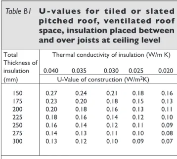
0.3.8 Appendix B contains tables of indicative U-values for certain common constructions. These are derived using the calculation methods referred to in Appendix A, and may be used in place of calculated or measured values, where appropriate. These tables provide a simple way to establish the U-value for a given amount of insulation. Alternatively they may be used to establish the amount of insulation needed to achieve a given U-value. The values in the tables have been derived taking account of typical repeated thermal bridging where appropriate. Where an element incorporates a non-repeating thermal bridge, e.g. where the continuity of insulation is broken or penetrated by material of reduced insulating quality, the U-value derived from the table should be adjusted to account for this thermal bridge. Table B24 in Appendix B contains indicative U-values for external doors, windows and rooflights (roof windows).
0.4 DIMEnSIOnS
0.4.1 Except where otherwise indicated linear measurements for the calculation of wall, roof and floor areas and building volumes should be taken between the finished internal faces of the appropriate external building elements and, in the case of roofs, in the plane of the insulation. Linear measurements for the calculation of the areas of external door, window and rooflight openings should be taken between internal faces of appropriate cills, lintels and reveals.
0.4.2 “Volume" means the total volume enclosed by all enclosing elements and includes the volume of non-usable spaces such as ducts, stairwells and floor voids in intermediate floors.
0.5 DEFInITIOnS
0.5.1 For the purposes of this Technical Guidance Document the following definitions apply:
Energy Use (for a particular purpose e.g. space heating, water heating, repeat cooling, ventilation, lighting): Energy input to the relevant system to satisfy the relevant purpose.
Delivered Energy: Energy supplied to the building and its systems to satisfy the relevant energy uses e.g.
space heating, water heating, cooling, ventilation, lighting. Delivered energy does not include renewable energy produced on site.
Delivered energy differs from energy use by the extent of on-site conversion and transformation losses e.g. boiler efficiency losses.
Primary Energy: Energy that has not been subjected to any conversion or transformation process. For a building, it is the delivered energy plus the energy used to produce the energy delivered to the building. It is calculated from the delivered energy, with an allowance for any energy exported from the site, using conversion factors.
Renewable Energy: Energy from renewable non-fossil energy sources e.g. solar energy (thermal and photovoltaic), wind, hydropower, biomass, geothermal, wave, tidal, landfill gas, sewage treatment plant gas and biogases.
Biomass: Biodegradable fraction of products, waste and residues from agriculture (including vegetal and animal substances), forestry and related industries, as well as biodegradable fraction of industrial and municipal waste, used as a fuel or energy source. Fuels derived from biomass may be in solid, liquid or gas form. In this document, where the term “biomass” is used on it’s own, it should be taken to mean solid biomass (wood, wood chip, wood pellet, etc).
Biofuel:Liquid or gas fuel derived from biomass. Note: Biomass(including biofuel) is generally included in Delivered Energy and thus, together with the energy used to produce and deliver it, included in
Primary Energy.
0.6
APPLICATIOn TO BUILDInGS OF
ARChITECTURAL OR hISTORICAL
InTEREST
0.6.1 Part L does not apply to works (including extensions) to an existing building which is a “protected structure” or a ‘proposed protected structure” within the meaning of the Planning and Development Act 2000 (No 30 of 2000).
Nevertheless, the application of this Part may pose particular difficulties for buildings which, although not protected structures or proposed protected structures may be of architectural or historical interest.
Works such as the replacement of doors, windows and rooflights, the provision of insulated dry lining and damp-proofing to walls and basements, insulation to the underside of slating and provision of roof vents and ducting of pipework could all affect the character of the structure.
In general, the type of works described above should be carefully assessed for their material and visual impact on the structure.
Historic windows and doors should be repaired rather than replaced, and drylining and damp-proofing should not disrupt or damage historic plasterwork or flagstones and should not introduce further moisture into the structure.
Roof insulation should be achieved without damage to slating (either during the works or from erosion due to condensation) and obtrusive vents should not affect the character of the roof.
In specific cases, relaxation of the values proposed may be acceptable, to the local building control authority, if it can be shown to be necessary in order to preserve the architectural integrity of the particular building.
For more guidance on appropriate measures see “Planning Guidelines No. 9: Architectural Heritage Protection - Guidelines for Planning Authorities” published by the Department of the Environment, Heritage and Local Government.
Section 1: Buildings other than
Dwellings
1.1: Limitation of Primary Energy Use and CO
2
emissions for New Buildings other than Dwellings
1.1.1
This Section provides guidance on how to show compliance with the requirements in relation to primary energy consumption and CO2 emissionsspecified in Regulation L4(a). The framework for calculation to be used is specified in the Regulation as the Non domestic Energy Assessment Procedure (NEAP). This framework enables the use of either a simplified building energy method or an approved alternative method. This framework is published by Sustainable Energy Ireland (SEI) and calculates the energy consumption and CO2 emissions associated
with a standardised use of a building. The energy consumption is expressed in terms of kilowatt hours per square metre floor area per year (kWh/m2/yr)
and the CO2 emissions expressed in terms of
kilograms of CO2 per square metre floor area per
year (kg CO2/m2/yr). Full details of the framework
are available on the SEI website at http://www.sei.ie.
1.1.2 The performance criteria are based on the relative values of the calculated primary energy consumption and CO2 emissions of a building being
assessed, and similar calculated values for a Reference Building. Details of the Reference Building are given in Appendix C. The criteria are determined as follows:
- Primary energy consumption and CO2
emissions for both the proposed building and the reference building are calculated using NEAP.
- The calculated primary energy consumption of the proposed building is divided by that of the reference building, the result being the energy performance coefficient (EPC) of the proposed building. To demonstrate that an acceptable Primary Energy consumption rate has been achieved, the calculated EPC of the building being assessed should be no greater than the Maximum Permitted Energy Performance Coefficient (MPEPC). The MPEPC is 1.0. - The calculated CO2 emission rate of the
proposed building is divided by that of the reference building, the result being the carbon performance coefficient (CPC) of the proposed building. To demonstrate that an acceptable CO2 emission rate has been
achieved, the calculated CPC of the building being assessed should be no greater than the
Maximum Permitted Carbon Performance Coefficient (MPCPC). The MPCPC is 1.0. Each method within the NEAP framework will calculate the EPC and CPC of the building being assessed and clearly indicate whether compliance with the requirements of Regulation L4(a) has been achieved.
1.1.3 The requirements that the calculated EPC and CPC do not exceed the MPEPC and MPCPC respectively, applies to the constructed building. Designers may wish to calculate the EPC and CPC at early design stage in order to ensure that the requirements can be achieved by the constructed building. However, the use of constructions and service systems which have been assessed at design stage, or other model designs, does not preclude the need to verify compliance by calculating the EPC and CPC when all relevant details of the final construction are known.
1.1.4 Primary energy does not include energy derived from on-site renewable energy technologies. In addition, as renewable energy technologies generally are characterised by zero, or greatly reduced, CO2emissions, the calculated EPC and CPC
are reduced by the extent that they replace traditional fossil fuels.
1.2: Heat Loss and Gain through the
Building Fabric
1.2.1 hEAT LOSS - GEnERAL
1.2.1.1 The following two methods may be used to demonstrate that an acceptable level of transmission heat loss through the elements bounding the heated building volume is
achieved-(a) The Overall Heat Loss method (paragraph 1.2.2). This method is applicable to new buildings and extensions to existing buildings; or
(b) The Elemental Heat Loss method (paragraph 1.2.3). While this method may be used for any building, it is primarily appropriate for small buildings, e.g. less than 300 m2 floor area, small
sections of large complex buildings, common areas of apartment blocks, material alterations and material changes of use.
For both methods, the guidance regarding the limitation of thermal bridging and uncontrolled air infiltration through the building fabric (paragraphs 1.2.4 and 1.2.5) and the control of overheating (paragraph 1.2.6) should be followed.
1.2.1.2 The derivation of U-values, including those applicable where heat loss is to an unheated space, is dealt with in Paragraphs 0.3.5 to 0.3.6 and Appendix A.
Unheated areas which are wholly or largely within the building structure and are not subject to excessive air-infiltration or ventilation, e.g. stairwells, corridors in buildings containing flats, may be considered as within the insulated fabric. In that case, if the external fabric of these areas is insulated to the same level as that achieved by equivalent adjacent elements, no particular requirement for insulation between the heated and unheated areas would arise.
1.2.1.3 The treatment of an attached conservatory-style sunspace is dealt with in Paragraph 0.1.6. Where an attached sunspace is treated as an extension to the main building for the purposes of assessment for compliance with the provisions of Part L (as provided for in Paragraph 0.1.6), the guidance in Paragraph 1.2.3.3 should be followed.
1.2.1.4 This Part of the Building Regulations applies to the replacement of external doors, windows, or rooflights in an existing building. The average U-value of replacement units should not exceed the value of 2.2 W/m2K. The limitations on opening
areas set out in Table 3 do not apply. In this context, the repair or renewal of parts of individual elements, e.g. window glass, window casement sash, door leaf should be considered as repair and not replacement.
1.2.2 OVERALL
hEAT
LOSS
METhOD
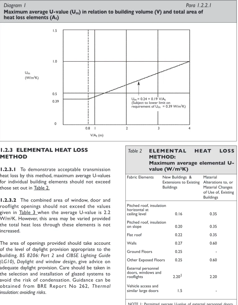
1.2.2.1 This method sets a maximum acceptable level of transmission heat loss through the fabric of a building, in terms of the maximum average U-value (Um) of all fabric elements contributing to heat loss.
The level depends on the ratio of the total area of these elements (At) to the building volume (V), and is
specified in Table 1. The acceptable level of heat loss is expressed graphically in Diagram 1.
1.2.2.2 In addition to not exceeding the maximum average value set, average elemental U-values should not exceed the following:
• roofs 0.25 W/m2K
• walls 0.37 W/m2K
• exposed floors 0.37 W/m2K
• ground floors 0.37 W/m2K
Area of Heat Loss Elements/ Maximum Average Building Volume U-Value (Um)
(At/V) (m-1) (W/m2K)
1.3 0.39
1.2 0.40
1.1 0.41
1.0 0.43
0.9 0.45
0.8 0.48
0.7 0.51
0.6 0.56
0.5 0.62
0.4 0.72
0.3 0.87
Table 1 Maximum average U-value (Um)
as a function of building volume (V) and fabric heat-loss area (At)
NOTE 1:The expression Um = 0.24 + 0.19 V/At can be used to establish Um for intermediate values of At/V and for values below 0.3 m-1.
1.2.3 ELEMEnTAL hEAT LOSS
METhOD
1.2.3.1 To demonstrate acceptable transmission heat loss by this method, maximum average U-values for individual building elements should not exceed those set out in Table 2.
1.2.3.2 The combined area of window, door and rooflight openings should not exceed the values given in Table 3 when the average U-value is 2.2 W/m2K. However, this area may be varied provided
the total heat loss through these elements is not increased.
The area of openings provided should take account of the level of daylight provision appropriate to the building. BS 8206: Part 2 and CIBSE Lighting Guide (LG10), Daylight and window design, give advice on adequate daylight provision. Care should be taken in the selection and installation of glazed systems to avoid the risk of condensation. Guidance can be obtained from BRE Report No 262, Thermal insulation: avoiding risks.
Diagram 1
Para 1.2.2.1
Maximum average U-value (U
m) in relation to building volume (V) and total area of
heat loss elements (A
t)
1.5
1.0
0.5 0.39
0
0.8 1 2 3 4 V/At(m)
Um= 0.24 + 0.19 V/At (Subject to lower limit on
requirement of Um = 0.39 W/m2K) Um
(W/m2K)
Fabric Elements New Buildings & Material
Extensions to Existing Alterations to, or Buildings Material Changes of Use of, Existing Buildings
Pitched roof, insulation horizontal at
ceiling level 0.16 0.35
Pitched roof, insulation
on slope 0.20 0.35
Flat roof 0.22 0.35
Walls 0.27 0.60
Ground Floors 0.25
-Other Exposed Floors 0.25 0.60 External personnel
doors, windows and
rooflights 2.201 2.20
Vehicle access and
similar large doors 1.5
-Table 2 ELEMEnTAL hEAT LOSS METhOD:
Maximum average elemental U-value (W/m2k)
NOTE 1: Permitted average U-value of external personnel doors, windows and rooflights in buildings other than dwellings may vary as described in Paragraph 1.2.3.2.
1.2.3.3 In applying Table 3 to an extension to an existing building, the relevant wall and roof areas may be taken to be:
(a) the combined areas for the existing building and extension; in this case the combined area of external door and window openings refers to the area of such openings in the extended building, i.e. the opening area of retained external doors, windows together with the opening area of external doors, windows in the extension; or
(b) the floor area of the extension alone; in this case the combined area of external doors, window and rooflight openings refers to the area of such openings in the extension alone. In this case the maximum combined area of external door, window and rooflight openings derived using Table 3 can be increased by an area equivalent to the area of external door, window and rooflight openings of the existing building which have been closed or covered over by the extension.
For extensions which
• are thermally separated from the adjacent spaces within the building by walls, doors and
other opaque or glazed elements which have U-values not more than 10% greater than corresponding exposed areas of the main building, and
• are unheated or, if provided with a heating facility, have provision for automatic temperature and on-off control independent of the heating provision in the existing building,
the limitation on the combined area of exposed external door, window and rooflight openings does not apply. In this case the average U-value of these elements should not exceed the value of 2.2 W/m2K.
1.2.3.4 There is a wide range of possible designs for external doors, windows and rooflights. Certified U-values should be used, where available. In the absence of certified data, U-values should be calculated in accordance with I.S. EN ISO 10077-1: 2000 or I.S. EN ISO 10077-2: 2000, as appropriate (See Appendix A). Alternatively, the indicative U-values for these components given in Table B24 can be used (see Appendix B).
1.2.3.5 Diagram 2 summarises the fabric insulation standards and allowances applicable in the Elemental Heat Loss method.
1.2.4 ThERMAL BRIDGInG
1.2.4.1To avoid excessive heat losses and local condensation problems, provision should be made to limit local thermal bridging, e.g. around windows, doors and other wall openings, at junctions between elements and at other locations. Any thermal bridge should not pose a risk of surface or interstitial condensation and any excessive increase in heat loss associated with the thermal bridge should be taken account of in the calculation of average U-value. The additional heat loss associated with
thermal bridges should be limited to less than 16% of the total calculated heat loss through the plane building elements.
Paragraphs 1.2.4.2. and 1.2.4.3 give guidance on the limitation of thermal bridging for typical locations in conventional construction. Alternatively Appendix D gives information on the calculation procedure
Building type Windows and doors Rooflights as % as % of the area of of area of roof exposed wall
Residential buildings (where people temporarily or
permanently reside) 30 20
Places of assembly,
offices and shops 40 20
Industrial and
storage buildings 15 20
Table 3 ELEMEnTAL hEAT LOSS METhOD
Maximum area of openings for average U-value of 2. (W/m2k)
NOTES:
1 For the purposes of this calculation, dormer windows in a roof may be included in the rooflight area.
2 Opening area excludes area of openings for vehicle access doors and display windows and similar glazing.
which can be used for the calculation of linear thermal transmittance of key junctions.
See Appendix D for further information in relation to thermal bridging and its effect on building heat loss.
1.2.4.2 Use of cill, jamb lintel and junction details set out
in-(a) “Right on the Site Issue No. 28”, published by HomeBond;
(b) “Limiting Thermal Bridging and Air Infiltration: Acceptable Construction Details” available on www.environ.ie
(c) other published details which have been assessed as satisfying the guidance in relation to Temperature Factor and Linear Thermal Transmittance set out in Appendix D, should represent reasonable provision to limit thermal bridging.
(d) designs similar to those shown in Diagram 3. At lintels, jambs and cills 15 mm thickness of insulation material having λ-values of 0.04
W/mK (or equivalent) will generally be adequate.
1.2.4.3 Care should be taken to control the risk of thermal bridging at the edges of floors. All slab-onground floors should be provided with edge insulation to the vertical edge of the slab at all external and internal walls. The insulation should have minimum thermal resistance of 0.7 m2K/W (25
mm of insulation with thermal conductivity of 0.035 W/mK, or equivalent).
Some large floors may have an acceptable average U value without the need for added insulation. However, perimeter insulation should always be provided. Perimeter insulation should extend at least 0.5 m vertically or 1 m horizontally. Where the perimeter insulation is placed horizontally, insulation to the vertical edge of the slab should also be provided as indicated above.
1.2.4.4 For new buildings the Heat Loss associated with thermal bridges is taken into account in calculating energy use and CO2 emissions in the
NEAP framework.
Where the details used are as described in 1.2.4.2 (a), (c) or (d) and 1.2.4.3 the psi values given in Table D1, Appendix D may be used for the NEAP calculation. Where the details used are those in 1.2.4.2 (b) the psi values given in Table D2 in Appendix D may be used.
Diagram 2
Para 1.2.3.5
Elemental heat Loss Method Summary of average elemental U-values
0.22
0.272
0.25
0.272
Average U-value 2.21
NOTES
1. Windows, doors and rooflights should have maximum U-value of 2.2 W/m2K and maximum opening area as set out in Table 6. However areas and U-values may be varied provided the total heat loss through these elements is not increased. 2. The U-value includes the effect of unheated voids or other spaces.
0.162
0.27 0.25 0.252
0.20
Unheated space Unheated attic
Diagram 3
Para 1.2.4.2
Lintel, jamb and sill designs
LINTELS JAMBS
HEAT LOSS PATHS without insulation
INTERNAL INSULATION
PARTIAL CAVITY FILL
FULL CAVITY FILL
NOTE
1. The internal faces of metal lintels should be covered with at least 15 mm of lightweight plaster; alternatively they can be dry-lined.
1.2.5 AIR InFILTRATIOn
1.2.5.1 Infiltration of cold outside air should be limited by reducing unintentional air paths as far as is practicable. A reasonably continuous air barrier should be provided over the whole thermal envelope, including elements separating the building from adjoining heated or unheated areas.
1.2.5.2 For conventional construction measures taken to ensure this should include:
(a) sealing the void between dry-lining and masonry walls at the edges of openings such as windows and doors, and at the junctions with walls, floors and ceilings (e.g. by continuous bands of bonding plaster or battens),
(b) sealing vapour control membranes in timber-frame constructions,
(c) fitting draught-stripping in the frames of openable elements of windows, doors and rooflights,
(d) sealing around access or service hatches which provide access to unheated voids (loft spaces) from the conditioned space,
(e) ensuring ducting for concealed services is sealed at floor and ceiling levels and sealing piped services where they penetrate or project into hollow constructions or voids. Diagram 4 illustrates some of these measures.
1.2.5.3 Additional guidance on appropriate measures to limit air infiltration in larger office and commercial buildings is given in BRE Report BR 448,
Air tightness in commercial and public buildings.
Guidance on methods to limit air infiltration through twin skin metal cladding and roofing systems is contained in Steel Construction Institute (SCI) Technical Information Sheet No. 311, The design of twin-skin metal cladding.
1.2.5.4 Air permeability can be measured by means of pressure testing of a building prior to completion. The procedure for testing is specified in IS EN 13829: 2000 “Thermal performance of buildings: determination of air permeability of buildings: fan pressurisation method”. Additional guidance on testing procedure is given in CIBSE Technical Manual TM 23 “Testing Buildings for Air leakage” and BRE document
BR 448 Tightness in Commercial and Public Buildings.
1.2.5.5 Care should be taken to ensure that measures to limit air infiltration do not negatively affect compliance with the ventilation requirements of Part F and Part J.
1.2.6 AVOIDInG SOLAR
OVERhEATInG
1.2.6.1 Buildings should be designed and constructed so that:
(a) those occupied spaces that rely on natural ventilation do not risk unacceptable levels of thermal discomfort due to overheating caused by solar gain, and
(b) those spaces that incorporate mechanical ventilation or cooling do not require excessive plant capacity to maintain the desired space conditions.
Where extensive use of glazing is proposed in the building design, particular care should be exercised to ensure compliance with this aspect of the Regulations.
1.2.6.2 Alternative approaches to showing compliance include:
(a) showing that the average daily solar heat load per unit floor area during the period of occupancy would not be greater than 25 W/m2, when the average solar load for glazing of different orientations is taken to be as specified in Table 4. The calculation procedure given in Appendix E can be used to do this. Local weather data averaged over a
Orientation Average solar load (W/m2)
N 125
NE/NW 160
E/W 205
SE/SW 198
S 156
Horizontal 327
Table 4 Average solar load between 7.30 and 17.30 for different glazing orientations
NOTE 1: This solar load is not likely to be exceeded on more than 2.5% of days in July. Source: CIBSE Guide A, Section 5.
period of 15 years, at least, can be used instead of the data given in Table 4, where available. (b) showing by detailed calculation procedures
such as those described in chapter 5 of CIBSE Guide A, that in the absence of mechanical cooling or mechanical ventilation, the space temperature will not exceed 280C for an
unacceptable proportion of the period of occupation. The period for which this temperature can be exceeded depends on the nature of occupancy and the activities within the space. For offices and similarly occupied buildings, a guide figure is 20 hours per annum during the period of occupancy. A range of computer simulation programs exists that facilitate this calculation.
1.2.6.3 Measures that can be effective in reducing the risk of solar overheating include:
(a) using glazing designed to reduce solar gains while not unduly limiting natural light transmittance,
(b) the incorporation of passive measures such as shading (detailed guidance in this regard is given in BRE Report No 364, Solar shading of buildings), and
(c) the use of exposed thermal capacity combined with night ventilation (detailed guidance in this regard is given in Action Energy General Information Report 31 (GIR031) Avoiding or minimizing the use of air-conditioning).
Diagram 4
Para 1.2.5.2
Air infiltration measures
Continuous seals (bonding plaster, battens or similar)
Seal at perimeter
Draught seal
Draught seal Bolt or catch to compress
draught seal Close fittinghole in
plasterboard
Seals 1. POSITION OF CONTINUOUS SEALING BANDS FOR
DRY-LININGS FIXED TO MASONRY WALLS
2. SEALING AT WINDOWS AND DOORS
3. SEALING ACCESS HATCH
4. SEALING AROUND SERVICE PIPES Ceiling
1.3:
Building Services
1.3.1 hEATInG PLAnT EFFICIEnCy
Heating plant should be designed and installed so that it operates efficiently over the range of loading likely to be encountered. Oil and gas fired boilers should satisfy the efficiency requirements specified in S.I. No. 260 of 1994: European Communities (Efficiency requirements for new hot water boilers fired with liquid or gaseous fuels) Regulations, 1994.
1.3.2 COnTROLS
FOR
SPACE
hEATInG AnD hOT WATER SUPPLy
SySTEMS
1.3.2.1 Space and water heating systems should be effectively controlled so as to limit energy use by these systems to that required to satisfy user requirements and, where appropriate, to protect the building and it’s contents from damage due to low temperatures. This section is not intended to apply to control systems for commercial and industrial processes.
1.3.2.2 Buildings should be provided with zone, timing and temperature controls such that, for space heating, each functional area is maintained at the required temperature only during the period when it is occupied. Additional space heating controls may be provided to allow heating during extended unusual occupation hours and to provide for sufficient background heating to prevent condensation or frost damage when the heating system would otherwise be switched off.
1.3.2.3 Hot water systems should be designed and provided with appropriate controls so that they can be operated efficiently. For efficient operation, hot water systems should not be over-sized and should be designed to avoid low-load operation of heating plant. The layout should minimize the length of circulation loops and minimize the length and diameter of dead legs. Designers should have particular regard to the need to limit the risk of promoting the growth of legionella bacteria. Local instantaneous heaters should be used, where appropriate. Consideration should be given to the use of renewable energy, e.g. solar water heating, and to heat recovery from other processes, where applicable. Electric water heating should be avoided except where demand is low.
1.3.2.4 Effective control of space and water heating can be achieved as follows:
(a) in buildings with a heating system of maximum output not exceeding 100 kW, by following the guidance in Action Energy Good Practice Guide 132 (GPG132) Heating Controls in small commercial and multi-residential buildings published by BRECSU;
(b) in larger or more complex buildings, by following the guidance contained in CIBSE Guide H: Building Control Systems published by CIBSE.
1.3.3 AIR COnDITIOnInG AnD
MEChAnICAL
VEnTILATIOn
(ACMV)
1.3.3.1 Buildings that use ACMV systems to treat in excess of 200 m2 floor area should be designed and
constructed such that:
(a) the form and fabric of the building do not result in a requirement for excessive installed capacity of ACMV equipment. In particular, the suitable specification of glazing ratios and solar shading are an important way to limit cooling requirements (see Section 1.2.6 above). (b) components such as fans, pumps and
refrigeration equipment are reasonably efficient and appropriately sized so as to have no more capacity for demand and standby than is necessary for the task.
(c) suitable facilities are provided to manage, control and monitor the operation of the equipment and the systems.
1.3.3.2 ACMV systems can be considered to be adequately sized if the specific fan power (SFP) is less than the values given in the following sub-paragraphs. The SFP is the sum of the design total circuit-Watts of all fans that supply air and exhaust it back to outdoors (i.e., the sum of supply and extract fans), including all losses through switchgear and controls such as inverters, divided by the design ventilation rate through the building.
(a) For ACMV systems in new buildings, the SFP should be no greater than 2.0 W/litre/second. (b) For new ACMV systems in refurbished
buildings, or where an existing ACMV system in an existing building is being substantially altered, the SFP should be no greater than 3.0 W/litre/second.
1.3.3.3 These SFP values are appropriate for typical ventilated spaces intended for human occupancy. Where specialist processes are involved or external pollution levels exceed those normally encountered and, as a result, greater levels of filtration or air cleaning are required, higher SFPs may be appropriate. In the context of this section “specialist processes” can be taken to include any activity which is not typical of the particular building use, which affects a significant area within the building, and where the resulting need for heating, ventilation or air conditioning is significantly different to that typical for the building. When assessing the performance of ACMV systems, areas where the existence or sizing of these systems is determined by process requirements should be excluded from the considered area, together with the plant capacity, or proportion of the plant capacity, that is provided to service those areas. Activities and areas in office buildings considered to represent process requirements would include:
- Staff restaurants and kitchens; - Large dedicated conference rooms; - Sports facilities;
- Dedicated computer or communications rooms.
1.3.3.4 Mechanical ventilation systems should be reasonably efficient at part load. This can be achieved by providing efficient variable flow control systems incorporating, for instance, variable speed drives or variable pitch axial fans. More detailed guidance is given in Action Energy General Information, Report 41 (GIR041) Variable flow control, General Information,published by BRECSU.
1.3.4 InSULATIOn OF STORAGE
VESSELS, PIPES AnD DUCTS
1.3.4.1 This section only applies to pipes, ducts and vessels for the provision of space heating, space
cooling (including chilled water and refrigerant pipe work) and hot water supply for normal occupation. It does not apply to pipes, ducts and vessels associated with commercial or industrial processes.
1.3.4.2 Hot water storage vessels, pipes and ducts associated with the provision of heating and hot water in a building should be insulated to limit heat loss, except where the heat flow through the wall of the pipe, duct or vessel is always useful in conditioning the surrounding space. Storage vessels for chilled water and refrigerant, and pipes and ducts that serve air-conditioning systems should be insulated to limit heat gain from the surrounding environment.
1.3.4.3 Provision of insulation to pipes, ducts and storage vessels, in accordance with the standards specified in BS 5422: 2001, should adequately limit heat loss or heat gain, as appropriate. The appropriate insulation level for storage vessels should be taken as that given in BS 5422: 2001 for flat surfaces.
1.3.4.4 It should be noted that water pipes and storage vessels in unheated areas will generally need to be insulated for the purpose of protection against freezing. Guidance on suitable protection measures is given in BRE Report 262, Thermal insulation: avoiding risks.
1.3.5 ARTIFICIAL LIGhTInG
1.3.5.1 The guidance given in Paragraphs 1.3.5.2 and 1.3.5.3 below need not be applied when the total installed lighting capacity is less than 1000 W. In this section the term “efficacy” is used to describe the energy efficiency of a lamp. It is described by the amount of light it produces in lumens with respect to the power it consumes in Watts.
1.3.5.2 General purpose artificial lighting systems shall be designed and controlled so as to ensure the efficient use of energy for this purpose. The efficiency of a general lighting system may be considered acceptable if it complies with one of the following:
(a) 95 % of the artificial lighting capacity in circuit Watts is provided by lighting fittings which use
lamps with luminous efficacies not less than those of the types listed in Table 5;
(b) the installed lighting capacity comprises lighting fittings with lamps having an average initial (100 hour) efficacy of not less than 65 lumens per circuit Watt; or
(c) the lighting design is in accordance with the guidance in the “Code for Lighting” published by CIBSE, in particular the guidance on energy efficiency in Section 2.4 of that document.
1.3.5.3 The aim of lighting controls should be to encourage the maximum use of daylight and to avoid unnecessary artificial lighting, particularly when spaces are unoccupied, having regard to the need to ensure that the operation of automatically switched lighting systems does not endanger occupants in a building. In this section reference to switches includes dimmer switches and switching includes dimming.
Adequate control depends on the nature and use pattern of the building. This may be achieved by one, or more, of the following means, used alone or in combination, as appropriate:
(a) local manually operated switches in easily accessible positions within each working area or at boundaries between working areas and general circulation routes. The distance on plan from any local switch to the luminaries it controls should generally be not more than eight metres, or three times the height of the light fitting above the floor if this is greater; (b) daylight-linked photo-electric switching or
dimming for lighting adjacent to windows or other sources of natural light;
(c) remote controlled switches operated by infra red transmitter, sonic, ultrasonic or telephone handset controls;
(d) automatic switching systems which switch the lighting off when they sense the absence of occupants;
(e) time-controlled switches.
For offices and storage buildings, local switching, either manual or remote controlled, is desirable. For some other building uses, e.g. where continuous lighting is required during hours of operation, time switching or daylight-linked photo-electric switching may be more appropriate.
Light source Types and rating
High pressure Sodium All types and ratings Metal halide All types and ratings Induction lighting All types and ratings Tubular fluorescent 26 mm diameter (T8) lamps,
and 16 mm diameter (T5) lamps rated above 11W, provided with high efficiency control gear. 38 mm diameter (T12) linear fluorescent lamps 2400 mm in length
Compact fluorescent All ratings above 11W Other Any type and rating with an
efficacy greater than 50 lumens per circuit Watt.
Table 5 Light sources suitable for general lighting
Appendix A:
Calculation of U-Values
GEnERAL
A1.1 General Guidance on the Calculation of U-values is contained in Report BR 443 “Conventions for U-value Calculations” 2006. For building elements and components generally, the method of calculating values is specified in I.S. EN ISO 6946: 1997. U-values of components involving heat transfer to the ground, e.g. ground floors with or without floor voids, basement walls, are calculated by the method specified in I.S. EN ISO 13370: 1999. A soil thermal conductivity of 2.0 W/mK should be used, unless otherwise verified. U-values for windows, doors and shutters may be calculated using I.S. EN ISO 10077-1: 2000 or I.S. EN ISO 10077-2: 2000. Information on U-values and guidance on calculation procedures contained in the 1999 edition of CIBSE Guide A3: Thermal Properties of Building Structures are based on these standards and may be used to show compliance with this Part.
A method for assessing U-values of light steelframed constructions is given in Digest 465 “U-values for light steel frame construction”, published by BRE. Guidance in relation to the calculation of U-values for various forms of metal clad construction can be found in Technical Paper No. 14 “Guidance for the design of metal roofing and cladding to comply with Approved Document L2: 2001”published by MCRMA, Technical Information Sheet No. 312, “Metal cladding: U-value calculation assessing thermal performance of built-up metal roof and wall cladding systems using rail and bracket spacers”published by SCI and IP 10/02 “Metal cladding: assessing thermal performance of built-up systems which use ‘Z’ spacers”published by BRE.
A1.2 U-values derived by calculation should be rounded to two significant figures and relevant information on input data should be provided. When calculating U-values the effects of timber joists, structural and other framing, mortar bedding, window frames and other small areas where thermal bridging occurs must be taken into account. Similarly, account must be taken of the effect of small areas where the insulation level is reduced significantly relative to the general level for the component or structure element under consideration. Thermal bridging may be disregarded, however, where the general thermal resistance does not exceed that in the bridged area by more than 0.1 m2K/W. For
example, normal mortar joints need not be taken
into account in calculations for brickwork or concrete blockwork where the density of the brick or block material is in excess of 1500 kg/m3. A
ventilation opening in a wall or roof (other than a window, rooflight or door opening), may be considered as having the same U-value as the element in which it occurs.
A1.3 Examples of the application of the calculation method specified in I.S. EN 6946: 1977 are given below. An example of the calculation of ground floor U-values using I.S. EN ISO 13370: 1999 is also given.
A1.4 Thermal conductivities of common building materials are given in Table A1 and for common insulating materials in Table A2. For the most part, these are taken from I.S. EN 12524: 2000 or CIBSE Guide A3. See Paragraph 0.3.3 regarding application of these Tables.
SIMPLE STRUCTURE WIThOUT
ThERMAL BRIDGInG
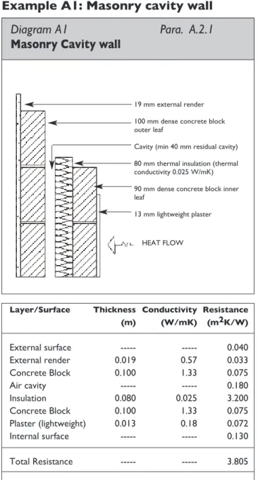
A2.1 To calculate the U-value of a building element (wall or roof) using I.S. EN ISO 6946: 1997, the thermal resistance of each component is calculated, and these thermal resistances, together with surface resistances as appropriate, are then combined to yield the total thermal resistance and U-value. The result is corrected to account for mechanical fixings (e.g. wall ties) or air gaps if required. For an element consisting of homogenous layers with no thermal bridging, the total resistance is simply the sum of individual thermal resistances and surface resistances.
I.S. EN 6946: 1997 provides for corrections to the calculated U-value. In the case of example A1 (see Diagram A1), corrections for air gaps in the insulated layer and for mechanical fasteners may apply. However, if the total correction is less than 3% of the calculated value, the correction may be ignored. In this case no correction for air gaps applies as it is assumed that the insulation boards meet the dimensional standards set out in I.S. EN ISO 6946: 1997 and that they are installed without gaps greater than 5 mm. The construction involves the use of wall ties that penetrate fully through the insulation layer.