Proc. 16 All India Conf. Manufacturing Technology Design and Research (AIMTDR), Banglore, Dec. 1994, pp. 289-295.
FORMAL SPECIFICATION OF PLC PROGRAMS USING TEMPORAL LOGIC
GIRISH KESHAV PALSHIKAR and KESAV V. NORI Tata Research Development And Design Centre (TRDDC),
1, Mangaldas Road, Pune 411050, INDIA
email: {pgirish, kvn}@trddc.ernet.in
ABSTRACT
Programmable Logic Controllers (PLC) form the backbone of automation in discrete manufacturing factories, power plants and other critical systems. Most PLC programming techniques do not facilitate program verification, modular development, code generation, easy maintenance etc. There is also a need to reduce the resources spent in development and maintenance of large PLC programs. To meet the stringent requirements of safety and performance of PLC programs and to facilitate hardware-independent logical modeling of the application system, we advocate the use of advanced software engineering techniques. A proposed project at TRDDC to develop an Automation Design And Management System (ADAMS) aims to fulfill all these goals. We outline the architecture of ADAMS. Then we examine characteristics of PLC programs and propose a paradigm shift to view them as reactive, real-time logic programs. We suggest using logic-based techniques to write formal specifications of PLC programs. We demonstrate how these specifications can be automatically verified in terms of similarly stated requirements. We show how these specifications can be executed for off-line simulation along with powerful input data-definition facilities to understand, analyze and debug the behavior of the system. Code for any particular PLC can be automatically generated from the specifications. We illustrate these concepts by specifying a conveyor-belt system in Prolog and First Order Linear Temporal Logic (FOLTL). We discuss the pros and cons of both approaches and outline future research.
1 INTRODUCTION
Most modern factories contain automated subsystems which are discrete, modular, decentralized and hierarchical
[1],[2]; we call such automation systems as Distributed
Automation Systems (DiAS). Programmable Logic Controllers (PLCs)[3], with attached equipment and
interconnection networks are backbones of such DiAS. We observe that a DiAS goes through a well-defined sequence of phases - Planning, Design, Implementation, Operations and Maintenance, which we call the
Automation Development Life Cycle (ADLC). The tasks
undertaken at each of these phases are of widely different nature. There is a clear need for an integrated software toolset to provide a comprehensive range of facilities to manage the complete life-cycle of a DiAS. We propose the name ADAMS (Automation Design And Management
System) for such an integrated workbench, which is
similar in spirit to a CASE toolset for software development.
In this paper, we view PLC programs as reactive,
real-time logic programs and discuss the use of mathematical
logic to model and specify the application and automatic verification of the properties of the given specifications. The rest of the paper is organized as follows: section 2 surveys the related work, section 3 briefly describes the motivations behind ADAMS, section 4 outlines the architecture of the ADAMS workbench, section 5 describes why and how PLC programs can be viewed as reactive, real-time logic programs, section 6 describes an example of a conveyor belt system commonly found in factories, sections 7 and 8 derive the formal specification of this system in Prolog and in temporal logic resp., section 9 compares the two specification techniques, section 10 draws the conclusions and indicates future work.
2 RELATED WORK
Proc. 16 All India Conf. Manufacturing Technology Design and Research (AIMTDR), Banglore, Dec. 1994, pp. 289-295.
specifications. Formal specifications are unambiguous and amenable to analysis and verification of properties. They can be re-used, executed, used as prototype and used for code generation. ESTEREL [4], Z, Petri Nets and temporal logic are used for specifications of reactive real-time systems. [5] surveys the theoretical aspects of temporal logics which are modal extension of predicate logic to deal with time varying properties and timing constraints. They have been used to specify software systems [6] and in particular, reactive systems [7]. [8] specifies a lift controller using a temporal logic. We are not aware of any effort to apply temporal logic to the specification of PLC programs. [9] uses Petri Nets and a logic-like rule language to specify PLC programs. [10] applies Petri Nets to specify the fault-tolerance requirements for real-time control systems, an important aspect of PLC programs. [11] reports the application of rule-based methodology to solving control problems. Since Logic Programming is also rule-based programming, [11] corroborates our approach. [12] uses logic-based Z notation to specify electronic instruments.
3 MOTIVATION FOR ADAMS
DiAS Life Cycle Management: A DiAS needs efficient
resource utilization and quick adjustments for goal changes. A DiAS is a strategically important, major investment in terms of money, man-power and capital. Comprehensive and integrated management of a DiAS is critical. ADAMS will help managers, with extensive tools for exploratory planning, design and specification, to ensure that proposed DiAS is feasible, cost-effective, and meets overall planning goals. ADAMS will similarly help in managing maintenance and upgrade of a DiAS.
Relevance To India: Large-scale automation, driven by
liberalization, is new to most Indian automation managers. Knowledge-based tools in ADAMS will help to plan, manage and commission large DiAS. ADAMS is specifically important and relevant to India.
Simulate Before You Implement: ADAMS allows
comprehensive experimentation and simulation of proposed DiAS to maximize objectives and gain confidence. ADAMS will reduce the implementation turn-around time. Early detection of shortcomings will save trouble and money.
Uniform, Logical View Of Automation: Although the
means of automation are diverse (being industry and task dependent), ADAMS provides integrated, uniform and logical views of the automation process to help in
planning, analysis, design and evaluation of the proposed DiAS.
Modern Software Engineering Techniques: Common
PLC programming techniques like Ladder Logic Diagram
(LLD), assembly or FORTRAN-like languages lack
formal foundations. Resulting programs are difficult to understand, analyze, prove properties, verify requirements, port, logically model and construct in top-down/modular way etc. Even graphical notation IEC 848 GrafCet based on Petri Nets does not solve these problems. Project management and other CASE tools (e.g. version control, data dictionary, library manager, debuggers, automatic documentation, reverse engineering tools etc.) are also not available. Advanced software engineering tools to address these problems will dramatically improve quality and reduce (unnecessarily high) costs of development and maintenance of PLC programs to control expensive and difficult processes and systems.
4 ADAMS- THE CONCEPT AND ARCHITECTURE
ADAMS is a new concept in integrated management of the life-cycle of a DiAS in a great variety of industries and services. ADAMS is envisaged to be a sophisticated, high performance, well-integrated and modular set of software tools to assist in every phase of the life-cycle of a DiAS. ADAMS provides flexible and powerful facilities to model and manage any existing or planned DiAS. ADAMS is an innovative product-line, which integrates a diverse range of software tools based on a variety of advanced and proven technologies. ADAMS clearly intends to push the state-of-the-art in automation management. Important aspects of ADAMS are:
o Knowledge-based Planner for high-level goals
o Comprehensive database of industry-standard PLCs and their associated information
o Knowledge-based Designer for DiAS design (as hierarchies and interconnections of clusters, segments and networks), layout, configuration and evaluation with respect to Planner goals
o Modular and formal specification of automation software and its verification and analysis
o Automatic generation of PLC code from specifications o Logical simulation language to define system-level
events, alarms, patterns of communication
o Distributed simulation to activate and animate entire, fully-running DiAS
o Sophisticated debugging with logical breakpoints, zoom-in, snapshots, playbacks, error-logs etc.
Proc. 16 All India Conf. Manufacturing Technology Design and Research (AIMTDR), Banglore, Dec. 1994, pp. 289-295.
o Advanced software engineering tools: repository, version control, library manager, graphical simulation output and other performance analysis tools etc.
o Automatic documentation of the organization of a DiAS and logic of each of its sub-systems in terms of reports, charts and diagrams.
o On-line DiAS specific help for training, operation, system-understanding etc.
o Intuitive graphical user interface, printer support, extensive hypertext-like intelligent on-line help
o Project management tools
ADAMS will help to streamline all the activities related to the ADLC of a DiAS. ADAMS will ease DiAS management, facilitate experimentation with cost-effective DiAS designs, improve the quality and reliability of the DiAS software implementation, reduce the turn-around time in delivering a DiAS and help in maintenance and training. ADAMS will help to achieve dramatic savings in automation costs and commissioning time. ADAMS will be useful to Automation Managers (plan, control and manage life-cycle of a DiAS), System Designers (DiAS design to meet planning goals and real-life constraints),
Industrial Engineers (development, implementation,
testing, maintenance of DiAS software), Automation
Consultants (guidance and problem-solving at all stages in
DiAS life-cycle), Field Support Executives (simulate, rectify, prevent field troubles; user training), Plant
Managers (training operators, engineers; efficient daily
operations) etc.
5 PLC PROGRAMS AS REACTIVE REAL-TIME LOGIC PROGRAMS
A PLC program is a physical interconnection of concurrently operating hardware devices which can also be viewed as logical composition logical objects. It is an event-driven system continuously interacting with the environment. It receives input signals and generates output signals. At a logical level the various signals and their processing are in perfect synchrony. Since these are the characteristics of reactive systems [4], PLC programs are reactive systems. PLC programs also contain timing instructions and constraints. PLC programs are implicitly based on real, physical time i.e. PLC programs are also real-time systems. Hence, we feel that PLC programs can be viewed as reactive, real-time systems.
A PLC programs as LLD specifies physical connections between devices. Treating input and output values as logical variables, and devices as objects, we see that LLD specifies a logical composition of devices and also the logical behavior of each device on the basis of its inputs.
The PLC has a fixed top-down, left-to-right control strategy to execute the LLD.
Logic Programming (LP) languages like Prolog [13] use
predicate logic as a programming language. Some features of Prolog are: declarativeness (stressing what than how), procedural interpretation for top-down refinement, firm mathematical foundation, uniform and standard query and rule language, portability, ease of use, efficiency and powerful compilers, debuggers and Expert System tools. Prolog programs deal with predicates which are logical objects and Prolog programs are logical composition of predicates. Prolog has similar top-down, left-to-right fixed execution control strategy. Prolog has been used for describing behavior of digital circuits. Hence, Prolog-based environments seem to be attractive for specification of PLC programs. We feel that PLC programs can be viewed as reactive, real-time logic programs to make available a firm formal foundation to understand, specify and analyze PLC programs. Our view is a new approach to PLC programming and this work is based on that premise.
6 A CONVEYOR BELT SYSTEM
Conveyor belts are an important component of manufacturing systems. Figure 1 shows a simple conveyor system [14] for which we will derive the formal specifications. It is easy to construct a state-transition diagram for this system from its description given below. The conveyor separates good parts from bad parts. Each part, when moving along the conveyor, turns on a series of 5 limit switches. A good part has height 1.0" ± 0.1". LS1 signals the arrival of a part on the conveyor. A good part turns on LS2 but not LS3. When it reaches LS4, it turns on solenoid SOL1 which moves the swingarm actuator and directs the good part into another conveyor. A bad part turns on both LS2 and LS3 (too large) or fails to turn on either switch (too small). After reaching LS5, it turns on SOL2 which moves the swingarm actuator and directs the bad part into the bad parts bin.
Proc. 16 All India Conf. Manufacturing Technology Design and Research (AIMTDR), Banglore, Dec. 1994, pp. 289-295.
of the conveyor's operational status. For simplification, we assume that at one time only one part is present on the conveyor.
7 SPECIFICATIONS IN PROLOG
Prolog specification of the conveyor system (appendix A) uses operational viewpoint (natural for engineers). Library IODEVICE allows the user to specify details of hardware devices in his system (e.g. limit-switches, lamps, timers, counters etc.) as Prolog facts and provides predicates for their manipulations (e.g. chk_on, chk_off, on, off,
set_timer_on, chk_timer_done etc.). Library INSIMUL
allows the user to specify the nature of the input data (e.g. distribution of good, bad and jammed parts) and automatically generates the input data to drive the simulation. Thus, the specifications can be executed (simulation of conveyor operations) to test or prove properties.
Top-level predicate go states that after start_conveyor succeeds (the conveyor is started), the conveyor continuously performs operation do_conveyor till
chk_stop_conveyor succeeds (it needs to stop). Predicate start_conveyor is refined to state that some initial
conditions must be fulfilled (chk_startup succeeds) before the actions to actually start the conveyor (do_startup) are done. Similarly, the predicate do_conveyor is refined to say that if the conditions for running the conveyor (chk_running) are OK and if a new part has arrived (chk_part_arrival) then process the part (process_part) and be ready for the next cycle (set_next_cycle). Refinement of chk_stop_conveyor says that if more data for simulation is available (chk_more_data) then fail else stop simulation. In the next refinement, predicates
chk_startup, do_startup specify the actual startup
conditions as well as actions to start the conveyor. Similarly, all other predicates in the previous level are refined. This clean process of top-down refinement of specifications continues until all aspects of the system's behavior are specified. This Prolog program can now be executed and its properties verified automatically.
8 SPECIFICATIONS IN TEMPORAL LOGIC
Temporal Logic is a formal system based on
mathematical logic for qualitative representation and reasoning about time and temporal behavior of systems.
First-order Linear Temporal Logic (FOLTL) [5] is a
one-sorted, point-oriented first-order logic. FOLTL supports a linear model of time where every moment has a unique successor. It also presumes the time to be discrete. Although it is not oriented towards real-time systems, we
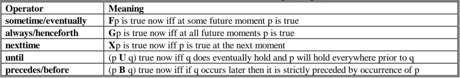
have chosen it for its simplicity. FOLTL adds temporal operators in Table 1 to first-order predicate logic to represent and reason about how truth of an assertion changes with time. We assume that all function, constant and predicate symbols are nontemporal and propositions and variables may be temporal or nontemporal. [5] defines the exact syntax and semantics of FOLTL. Temporal logics have been used to specify and verify nonterminating concurrent and reactive programs like protocols, Operating Systems etc.
Appendix B gives the specification of the conveyor system in FOLTL. These specification are written from the point of view of identifying events and their processing; e.g. the specification for conveyor startup says that if at any time the START button is pushed and STOP button is not pushed then there comes a time when motor is started and there comes another moment when the run lamp is put on. All other specifications can be similarly and easily understood.
9 COMPARING PROLOG AND FOLTL
Prolog allows a clean process of top-down refinement of logical specifications which can be executed and its properties verified automatically. The specifications start at logical level and are refined successively till they reach the hardware level. This logical view of the system is absent in LLD and other approaches for PLC programming. Prolog also offers advantages like popular, portable, efficient development environments, clean and simple semantics etc. Prolog also allows clean and powerful off-line simulation, debugging and analysis facilities. Simple properties of the system which always hold (e.g. good swingarm and bad swingarm never open simultaneously) or which hold at specific time-points (e.g. JAM light comes on and conveyor stops after a jam occurs) can be easily verified. However, it is difficult to use Prolog to verify more complex properties which hold over conditionally defined intervals. FOLTL is clearly powerful and expressive. However, it lacks some features necessary for real-time systems as well as it does not have efficient techniques for execution of specifications and for verification of its properties. Stepwise development of operational specifications is difficult in such logics.
10 CONCLUSIONS AND FUTURE WORK
Proc. 16 All India Conf. Manufacturing Technology Design and Research (AIMTDR), Banglore, Dec. 1994, pp. 289-295.
currently defining such a language, its temporal features and its semantics. Development of ADAMS will shortly
be undertaken.
ACKNOWLEDGMENTS
We are grateful to Dr. E.C. Subbarao for his constant encouragement. We acknowledge the interest and help from A.K. Gupta and members of his Process Control Group - K. Krishna, Milind Joshi, Sanjeev Dange, Nivedita Mitra and others. Hanumantha Rao, Pavan Kumar, Vivek Balaraman, Shailesh Abhyankar, Dr. Balachandran, Vinay Kulkarni and many others at TRDDC have been enthusiastic and freely contributed their time and ideas.
REFERENCES
[1] Komoda N., Kera K., Kubo T., 'An Autonomous, Decentralized Control System For Factory Automation', IEEE Computer, Vol. 50, No. 12, Dec. 1984, pp. 73-83.
[2] Tanimoto H., 'Factory Automation: An Automatic Assembly Line For The Manufacture Of Printers', IEEE Computer, Vol. 50, No. 12, Dec. 1984, pp. 50-68.
[3] Groover M.P., 'Automation, Production Systems And Computer Integrated Manufacturing', Prentice-Hall, 1986.
[4] Berry G., Gonthier G., 'The ESTEREL Synchronous Programming Language: Design, Semantics, Implementation', Science Of Computer Programming, Vol. 19, 1992, pp. 87-152.
[5] Emerson E.A., 'Temporal And Modal Logic', in Handbook Of Theoretical Computer Science, J.van Leeuwen, Ed. Elsevier Science Publishers, 1990.
[6] Banieqbal B., Barringer H., Pneuli A., eds., 'Temopral Logic In Specification', LNCS 398, Springer-Verlag, 1987.
[7] Pneuli A., 'Application Of Temporal Logic To Specification And Verification Of Reactive Systems: Survey Of Current Trends', in J.W.DeBakker ed., Current Trends In Concurrency: Overviews and Tutorials, LNCS 224, Springer-Verlag, 1986.
[8] Hale R., 'Using Temporal Logic For Prototyping', in Temporal Logic For Specifications. B. Banieqbal et al, eds. LNCS 398, pp. 375-408, Springer-Verlag, 1987.
[9] Willson R.G., Krogh B.H., 'Petri Net Tools For The Specification And Analysis Of Discrete Controllers', IEEE Trans. Soft. Engg., Vol. 16, No. 1, Jan. 1990, pp. 39-50.
[10] Belli F., Grosspietsch K.-E., 'Specification Of Fault-Tolerant System Issues By Predicate/Transition Nets And Regular Expressions-Approach And Case Study', IEEE Trans. Soft. Engg., Vol. 17, No. 6, Jun. 1991, pp. 513-526.
[11] Etessami F.S., Hura G.S., 'Rule-Based Design Methodology For Solving Control Problems', IEEE Trans. Soft. Engg., Vol. 17, No. 3, Mar. 1991, pp. 274-282.
[12] Delisle N., Garlan D., 'Formally Specifying Electronic Instruments', Proc. 5th Int. Workshop Soft. Spec. Design, IEEE CS Press, 1989, pp. 242-248.
[13] Clocksin W.F. , Mellish C.S., 'Programming In Prolog', 3/e. Springer-Verlag, 1989. [14] Allen-Bradley Corp., 'PLC-30 Reference Manual', Ch. 17.
Table 1. Some common linear temporal operators.
Operator Meaning
sometime/eventually Fp is true now iff at some future moment p is true always/henceforth Gp is true now iff at all future moments p is true nexttime Xp is true now iff p is true at the next moment
until (p U q) true now iff q does eventually hold and p will hold everywhere prior to q
Proc. 16 All India Conf. Manufacturing Technology Design and Research (AIMTDR), Banglore, Dec. 1994, pp. 289-295.
ls1 ls2 ls3 ls4 ls5
part
sol1 sol2
ctr
sol3 bad part bin swingarm actuator swingarm actuator
good part conveyor
movement of part --->
0.9" <= good part height <= 1.1"
ls2 set at 0.9"
ls3 set at 1.1" START STOP
RUN JAM
Figure 1. Conveyor Belt: separating good parts from bad parts.
APPENDIX A. PROLOG SPECIFICATIONS OF THE CONVEYOR SYSTEM Note: Some low-level predicates are not shown.
go :- start_conveyor,
repeat, do_conveyor, /* process one part */
chk_stop_conveyor. /* process next part if no need to stop */ start_conveyor
:-chk_startup, /* chk that conveyor is ready to be started */ do_startup. /* start the conveyor */
do_conveyor
:-chk_running, /* chk that conditions to run conveyor are OK */ chk_part_arrival, /* ensure that the part arrives on the conveyor */ process_part, /* process the arrived part */
set_next_cycle. /* be ready for the next cycle */ chk_stop_conveyor
:-chk_more_data, /* input data for next cycle is present */
!, fail. /* do not stop as conveyor's next cycle can be run */ chk_stop_conveyor :- write('No more input data! Conveyor simulation over.'), nl. chk_startup :- /* TRUE if conveyor is ready to be started */
chk_on( read, start ), /* START pushbutton must be pushed */ chk_on( read, stop ). /* STOP pushbutton must not be pushed */ do_startup :- /* start the conveyor */
on( motor_starter ), /* start conveyor motor */ on( motor_starter_aux ), /* start motor starter aux */
on( run ). /* switchon the RUN indicator lamp */
chk_running :- chk_start, /* START is pushed or motor_starter_aux is ON */ chk_on( read, stop ), /* STOP push-button must not be pushed */ chk_off( read, jam ). /* chk that JAM indicator is OFF */
chk_running :- write('Conveyor stopped! Re-start data not available!'), nl, abort(0). chk_part_arrival :- chk_on( read, ls1 ), /* limit-switch 1 must be ON */
set_timer_on( t0 ), /* start watchdog timer t0 */ set_timer_on( t2 ). /* start watchdog timer t2 */
process_part :- separate_good_part. /* separate part as per whether it is good or bad */ process_part :- separate_bad_part.
chk_start :- chk_on( read, start ). /* START pushed or motor_starter_aux ON*/ chk_start :- chk_on( get, motor_starter_aux ).
Proc. 16 All India Conf. Manufacturing Technology Design and Research (AIMTDR), Banglore, Dec. 1994, pp. 289-295.
chk_good_part :- above_min_height, below_max_height. process_good_part :- chk_jam_good_part, remove_jam_good_part,
write('Good part JAMmed! Stopping the conveyor!!'), nl. process_good_part :- remove_good_part, write('Good part found! '), nl. chk_bad_part :- not( chk_good_part ).
process_bad_part :- jam_bad_part, remove_jam_bad_part, write('Bad part JAMmed! Stopping the conveyor!!'), nl. process_bad_part :- remove_bad_part, write('Bad part found! '), nl.
above_min_height :- chk_on( read, ls2 ). /* LS2 on iff part above min height*/ below_max_height :- chk_off( read, ls3 ), /* LS3 on iff part below max height*/ chk_jam_good_part :- read_timed_limit_switch( ls4, t0 ), chk_timer_timeout( t0 ). chk_jam_bad_part :- read_timed_limit_switch( ls5, t2 ), chk_timer_timeout( t2 ). remove_jam_good_part :- off( ls4 ), off( motor_starter ), on( jam ).
remove_jam_bad_part :- off( ls5 ), off( motor_starter ), on( jam ). remove_good_part :- actuate_good_swingarm.
remove_bad_part :- actuate_bad_swingarm, inc_bad_counter, dump_bad_bin. actuate_good_swingarm :- chk_on( read, ls4 ), on( sol1 ), off( ls4 ).
actuate_bad_swingarm :- chk_on( read, ls5 ), on( sol2 ), off( ls5 ).
dump_bad_bin :- chk_counter( bad_ctr, done ), open_bad_bin_bottom. dump_bad_bin.
open_bad_bin_bottom :- write('Opening the bottom of the bad part bin!'), nl,on( sol3 ), wait_bad_bin_empty, /* wait till bad bin is empty */
off( sol3 ).
APPENDIX B. FOLTL SPECIFICATIONS OF THE CONVEYOR SYSTEM
conveyor start: (chk_off(start) ∧ X(chk_on(start)∧chk_off(stop)))
Fchk_on(motor_starter) ∧ Fchk_on(motor_starter_aux) ∧ Fchk_on(run)
conveyor stop: (chk_on(stop) ∨ chk_on(jam)) Fchk_off(motor_starter) ∧ Fchk_off(motor_starter_aux) ∧ Fchk_off(run)
part arrival: on(ls1) Fchk_timer_on(t0) ∧ Fchk_timer_on(t2)
good part movement: chk_timer_on(t0) U chk_on(ls4) ∨ chk_timer_timeout(t0))
good part jam: chk_timer_timeout(t0) Fchk_off(motor_starter) ∧ Fchk_off(motor_starter_aux) ∧ Fchk_off(run) ∧
Fchk_on(jam)
good part processing: (chk_on(ls2) ∧ chk_off(ls3) ∧ chk_on(ls4)) Fchk_on(sol1) ∧
Fchk_off(ls2) ∧ Fchk_off(ls4) ∧ Fchk_timer_off(t0)
bad part movement: chk_timer_on(t2) U (chk_on(ls5) ∨ chk_timer_timeout(t2))
bad part jam: chk_timer_timeout(t2) Fchk_off(motor_starter) ∧ Fchk_off(motor_starter_aux)∧Fchk_off(run) ∧
Fchk_on(jam)
bad part processing: (∼(chk_on(ls2) ∧ chk_off(ls3)) ∧ chk_on(ls5)) Fchk_on(sol2) ∧
Fchk_off(ls2)∧Fchk_off(ls3) ∧ Fchk_off(ls5) ∧ Fchk_timer_off(t0) (chk_on(sol2) ∧ chk_off(bad_ctr)) Fchk_counter_on(bad_ctr) ∧ Finc_counter(bad_counter) (chk_on(sol2) ∧ chk_on(bad_ctr)) Finc_counter(bad_counter)