METAL-ORGANIC FRAMEWORKS AS SINGLE-SITE ASYMMETRIC CATALYSTS
Joseph Falkowski
A dissertation submitted to the faculty of the University of North Carolina at Chapel Hill in partial fulfillment of the requirements for the degree of Doctor of Philosophy in the
Department of Chemistry (Inorganic).
Chapel Hill 2013
ii ABSTRACT
JOSEPH FALKOWSKI: Metal-Organic Frameworks as Single-Site Asymmetric Catalysts
(Under the direction of Wenbin Lin)
iii
Acknowledgements
A doctoral program can best be described as a gauntlet, an endurance trial that tests the mettle of those who attempt it. No student can possibly hope to succeed without the support of—in no particular order—their faculty, advisors, colleagues, undergraduates, friends and family. To all these people who have helped and carried me through the last five years in the best and worst of times, I could not have done this without you. This is a victory not unto me but to you as well.
iv
TABLE OF CONTENTS
LIST OF TABLES ... xii
LIST OF FIGURES ... xiii
LIST OF ABBREVIATIONS ... xxiii
Chapter I. METAL-ORGANIC FRAMEWORKS FOR ASYMMETRIC CATALYSIS – AN INTRODUCTION ...1
1.1 Why asymmetric catalysts, and why metal-organic frameworks?...1
1.2 Sources of Chirality ...3
1.3 Benefits of MOFs in asymmetric catalysis ...5
1.4 First Examples of Asymmetric Catalysis ...6
1.5 Outlook and future directions ...12
References ...14
II. ISORETICULAR CHIRAL METAL-ORGANIC FRAMEWORKS AS A TUNABLE PLATFORM FOR ASYMMETRIC CATALYSIS ...16
2.1 Introduction ...16
2.2 Results and Discussion ...18
2.2.1 Synthesis and characterization of isoreticular CMOFs ...18
2.2.2 Enantioselective catalysis ...29
2.3 Conclusions ...36
2.4 Experimental ...37
2.4.1 General Procedures and Instrumentation ...37
iv
Synthesis of (R
)-2,2’-diethoxy-1,1’binaphthyl-4,4’,6,6’-tetracarbonitrile. ...38
Synthesis of (R)-2,2’-diethoxy-1,1’binaphthyl-4,4’,6,6’ -tetracarboxylic acid (L1a-H4). ...39
Synthesis of (R)-(2E,2'E,2''E,2'''E)-tetramethyl 3,3',3'',3'''-(2,2'-diethoxy-1,1'-binaphthyl-4,4',6,6'-tetrayl)tetraacrylate (L2a-Me4) ...39
Synthesis of (R)-(2E,2'E,2''E,2'''E )-3,3',3'',3'''-(2,2'-diethoxy-1,1'-binaphthyl-4,4',6,6'-tetrayl)tetraacrylic acid (L2a-H4) ...40
Synthesis of (R)- Tetramethyl 4,4',4'',4'''-(1E,1'E,1''E,1'''E)- 2,2',2'',2'''-(2,2'-diethoxy-1,1'-binaphthyl-,4',6,6'tetrayl)tetrakis (ethene-2,1-diyl)tetrabenzoate (L4a-Me4) ...41
Synthesis of (R)-4,4',4'',4'''-(1E,1'E,1''E,1'''E)-2,2',2'',2'''-(2,2'- diethoxy-1,1'-binaphthyl-4,4',6,6'-tetrayl)tetrakis(ethene-2,1-diyl)tetrabenzoic acid (L4a-H4) ...43
Synthesis of (R) - Tetramethyl 2,2'-diethoxy-1,1'-binaphthyl-4,4' ,6,6'-tetracarboxylate (L1a-Me4) ...44
Synthesis of (R) - 2,2'-dihydroxy-1,1'-binaphthyl-4,4',6,6'-tetracarboxylic acid (L1b-H4)...44
Synthesis of (R)-(2E,2'E,2''E,2'''E )-3,3',3'',3'''-(2,2'-dihydroxy-1,1'-binaphthyl-4,4',6,6'-tetrayl)tetraacrylic acid (L2b-H4) ...45
Synthesis of (R)-2,2’-dihydroxy-1,1’-dinaphthyl-4,4’,6,6’-tetrakis (4-benzoic acid)(L3b-H4) ...46
Synthesis of (R)- 4,4',4'',4'''-(1E,1'E,1''E,1'''E )-2,2',2'',2'''-(2,2'- dihydroxy-1,1'-binaphthyl-4,4',6,6'-tetrayl)tetrakis(ethene-2,1-diyl)tetrabenzoic acid (L4b-H4) ...47
2.4.3 Synthesis of isoreticular CMOFs ...48
Synthesis of [R – L1aCu2(DEF)2]•3.5DEF•4H2O (CMOF-1a) ...48
Synthesis of [R – L2aCu2(H2O)2]• 9 DMF • 14 H2O (CMOF-2a) ...49
Synthesis of [R – L4aCu2(H2O)2] • 10 DEF • 14 DMA • 5 H2O (CMOF-4a) ...51
v
Synthesis of [R – L2bCu2(H2O)2] • 11 DEF 3H2O (CMOF-2b) ...54
Synthesis of [R - L3bCu2(H2O)2 ] 13 DMF 11 iPrOH 4.5 • H2O (CMOF-3b) ...55
Synthesis of [R – L4bCu2(H2O)2] •6.5 DEF • 19 DMF • 8.5 iPrOH (CMOF-4b) ...57
2.4.4 X-ray Structure Determination ...59
2.4.5 Quantitative determination of the content of solvent molecules ...63
2.4.6 X-ray Powder Diffraction ...64
2.4.7 Structure Figures ...69
2.4.8 Dye uptake measurements ...71
2.4.9 Grand Canonical Monte Carlo (GCMC) simulation of nitrogen adsorption isotherms ...73
2.4.10 Procedures and results for MOF-catalyzed alkylzinc addition to aromatic aldehydes...75
General procedure for diethylzinc addition to aromatic aldehydes ...75
General procedure for ethylphenylethynyl zinc additions to aromatic aldehydes...76
Diethylzinc addition reactions using the supernatant of the CMOF catalysts ...77
Catalysis control experiment using CMOF-3a ...77
Alkynylzinc addition reactions using the supernatant of the CMOF catalysts ...77
Catalysis control using L3b-Me4 ...78
MOF catalyst recycle and reuse ...78
References ...79
III. ACTUATION OF ASYMMETRIC CYCLOPROPANATION CATALYSTSVIA REVERSIBLE SINGLE-CRYSTAL TO SINGLE- CRYSTAL REDUCTION OF METAL-ORGANIC FRAMEWORKS...83
vi
3.2 Results and discussion ...84
3.2.1 Synthesis of Ru(salen) ligands and MOFs ...84
3.2.2Single-crystal to single-crystal reduction of ruthenium- SALEN frameworks...88
3.2.3MOF-catalyzed cyclopropanation of alkenes ...90
3.3 Concluding remarks ...93
3.4 Experimental ...94
3.4.1 General Procedures and Instrumentation ...94
3.4.2 Procedures for ligand synthesis ...95
(R,R)-(-)-N,N'-Bis(methyl-3-carboxyl-5-tert-butylsalicylidene)- 1,2-cyclohexanediamine dipyridyl ruthenium(II) [Ru(L5-Me2)(py)2]...95
(R,R)-(-)-N,N'-Bis(3-carboxyl-5-tert -butylsalicylidene)-1,2-cyclohexanediamine dipyridyl ruthenium (III) Chloride [Ru(L 5-H2)(py)2Cl] ...96
(R,R)-N,N’-bis(3-methylacrylate-5-tert -butylsalicylidene)-1,2-cyclohexanediamine (L6-Me2) ...96
(R,R)-N,N’-bis(3-methylacrylate-5-tert -butylsalicylidene)-1,2-cyclohexanediamine dipyridyl Ruthenium(II) [Ru(L6-Me2)(py)2] ... 97
(R,R)-N,N’-bis(3-methylacrylate-5-tert -butylsalicylidene)-1,2-cyclohexanediamine dipyridyl Ruthenium(III) chloride {[Ru(L 6-H2)(py)2]Cl} ... 98
3.4.3 Procedures for MOF synthesis ...99
Synthesis of Zn4O(L5)3∙(DEF)7∙(DBF)7 (CMOF-5)...99
Synthesis of Zn4O(L5)3∙(DEF)19∙(DMF)5∙(H2O)17 (CMOF-6) ...100
Synthesis of Zn4O{Ru(L6)(py)2]Cl}3∙5(DBF)∙ 3.5(DMF) (CMOF-7) ...102
vii
3.4.4 X-Ray structure Determination ...105
3.4.5 Dye Inclusion studies ...118
Representative procedure for dye uptake measurements ...118
3.4.6 Single-Crystal to Single-Crystal reduction ...120
Procedure for Single-Crystal to Single-Crystal reduction ...120
Spectroscopic characterization of reduced species ...121
3.4.7 Asymmetric Cyclopropanation Reactions ...124
Asymmetric Cyclopropanation Reactions with CMOFs ...124
Homogenous test of methylated ligand without reducing agent ...124
Homogenous test of methylated ligand with reducing agent ...125
Reaction of EDA with styrene using CMOF-6 ...125
Test for reactivity of supernatant ...125
Test for reactivity of Zn-BPDC ...126
Recycling tests of MOF catalyst ...127
Catalyst leaching measurments by UV-Vis and ICP-MS ...127
References ...129
IV. ANION-CONTROLLED CATENATION OF A METALLOSALEN METAL-ORGANIC FRAMEWORK ...131
4.1 Introduction ...131
4.2 Results and discussion ...133
4.2.1 Synthesis of elongated Ru(salen) ligand ...133
4.2.2 Anion controlled synthesis of a pair of catenation-related frameworks ...134
4.3 Concluding remarks ...137
4.4 Experimental Details ...138
4.4.1 General experimental ...138
viii
(R,R)-N,N’-bis(3-[methyl-4-benzoate]-5-tert-butylsalicylidene)-
1,2-cyclohexanediamine (L7-Me2) ...139
(R,R)-N,N’-bis(3-methyl acrylate-5-tert -butylsalicylidene)-1,2-cyclohexanediamine dipyridyl Ruthenium(II) [Ru(L7-Me2)(py)2] ... 139
(R,R)-N,N’-bis(3-methyl acrylate-5-tert -butylsalicylidene)-1,2-cyclohexanediamine dipyridyl Ruthenium(III) chloride {[Ru(L7)(py)2]Cl} ... 141
4.4.3 Procedures for MOF synthesis ...141
Synthesis of Zn4O{Ru(L7)(Py)2]Cl}3∙ (CMOF –9) ...141
Synthesis of Zn4O{Ru(L7)(Py)2]Cl}2.7{Ru(L)(py)2(BPh4)}1.3 (CMOF – 10)...142
4.4.4 X-ray Diffraction studies ...143
4.4.5 Procedure for Dye Uptake Measurements ...146
4.4.6 Asymmetric cyclopropanation reactions...146
4.4.7 Determination of boron content in CMOF – 10...149
References ...150
V. PRIVILEGED PHOSPHINE-BASED METAL-ORGANIC FRAMEWORKS FOR BROAD SCOPE ASYMMETRIC CATALYSIS ...151
5.1 Introduction ...151
5.2 Results and discussion ...153
5.2.1 Synthesis of substituted BINAP ligands and a BINAP-based metal-organic framework ...153
5.2.2 Catalytic hydorgenations and conjugate additions using MOFs as a chiral precatalyst ...156
5.3 Concluding remarks ...161
5.4 Experimental Details ...163
5.4.1 General experimental ...163
5.4.2 Procedure for ligand synthesis ...164
4,4’-diiodoBINAPoxide ...164
ix
4,4’-bis(methyl-4-carboxyphenylacetyl)BINAP (L8-Me2) ...165
4,4’-bis(4-carboxyphenylacetyl)BINAP(L8-H2) ...166
5.4.3 Procedure for MOF synthesis ...167
Synthesis of Zr6(OH)4O4(L8)6∙5(DBF)∙3.5(DMF) (CMOF-11) ...167
5.4.4 X-ray structure determination ...167
5.4.5 Post-synthetic metallation of CMOF – 11 ...168
5.4.6 Heterogeneous catalysis studies with post-synthetically metallated CMOF – 11 ...170
Catalytic hydrogenation with CMOF – 11·Ru...170
Test of supernatant of CMOF – 11·Ru for catalytic activity ...179
Catalytic hydrogenation with CMOF – 11·Rh...181
Catalytic 1,4-conjugate additions of aryboronic acids to α-β unsaturated ketones with CMOF – 11·Rh ...183
xii
LIST OF TABLES
1-1. The various methods of introducing chirality into a metal-organic framework ...3
2-1. Summary of key parameters and characterization data for CMOFs ...23
2-2. Diethylzinc additions to aromatic aldehydes catalyzed by the CMOF/Ti(OiPr)4
combinations. ...24
2-3. Alkynylzinc additions to aromatic aldehydes catalyzed by the CMOF/Ti(OiPr)4
combinations ...35
2-4. Crystal data and structure refinement for isoreticular CMOFs ...60
3-1. Asymmetric cyclopropanation of substituted olefins using CMOF catalysts. ...92
3-2. Crystal data and structure refinements for CMOFs 5, 6, 5R, 6R and RuIII(salen) complex ...106
3-3. Unit cell parameters of crystals of CMOFs 5’and 6’. ...107 3-5. Crystal data and structure refinements for CMOF-7 and 8 ...112 4-1. Comparison of the 9- and 10-catalyzed cyclopropanation reaction of styrene with
previously reported Ru(salen)-MOF catalysts ...137
5-1. Hydrogenation of substituted alkenes and β-keto esters by CMOF-11·Ru and Ru(L8
-Me2)Cl2(DMF)2 ...157
xiii
LIST OF FIGURES Figure
1-1. Inter- vs. intramolecular coordination of titanium as revealed by X-ray diffraction. The crystallinity of MOFs offers unique opportunities to elucidate
structure/function relationships ...6 1-2. The synthesis of a face-on hexagonal two-dimensional framework and the
kinetic resolution of 1-phenyl-2-propanol as reported by Kim and coworkers ...7 1-3. A 2-dimensional, lamellar, chiral framework and its activity in the asymmetric
ring opening of meso-epoxides ...8 1-4. The synthesis of a 3-dimensional chiral framework from a 4,4’-pyridyl
substituted BINOL ligand .The framework consists of a 2-dimentional network consisting of zig-zag chains of Cd(µ-Cl)2 SBUs (red chains) connected
by hydrogen-bonded ligand pairs (blue rods). The 2-dimensional layer s are connected by a third ligand (yellow rods) to form the 3-dimensional
framework ...9 1-5. Epoxidation of 2,2,-dimethyl-2H-chromene using a pillared MOF framework
reported by Hupp and coworkers ...10 1-6. Synthesis of a series of chiral MOFs with varying channel sizes controlled by
framework catenation and ligand length ...12 2-1. Schematic representation of a homochiral MOF and its postsynthetic
modification (PSM) to a catalytically active MOF. (a) Cartoon showing the assembly of CMOFs and their postsynthetic modification to afford heterogenized asymmetric catalysts. (b) The chemical structures of the ligands used for this study. The L1a-L4a and L1b-L4b notations are used to described both the protonated (as in free ligands) and deprotonated forms (as in CMOFs) of (R)-tetracarboxylic acids. R = Et for CMOF-1a to -4a and R = H for CMOF-1b to -4b. The primary carboxylic acid groups highlighted in red are used to form CMOFs whereas the secondary dihydroxy groups highlighted in blue will react with Ti(OiPr)4 upon postsynthetic modification
to form asymmetric catalysts ...17 2-2. Crystal structure of CMOF-1a. (a) A view of [Cu2(O2CR)4] paddle-wheels
and their connectivity with the L1a ligands in CMOF-1a. (b) Representation of the L1a ligand as a blue distorted tetrahedron and the [Cu2(O2CR)4] paddle-wheel as a red square. (c) A simplified connectivity scheme of L1a ligands (blue distorted tetrahedra) and [Cu2(O2CR)4] paddle-wheels (red squares). (d) Stick model of CMOF-1a as viewed down the a axis. (e) A simplified connectivity of CMOF-1a as viewed down the a axis
xiv
2-3. Space-filling models showing packing diagrams of CMOF-1b to -4b. The figures on the left (a, c, e, and g) show the packing diagrams of CMOF-1b to -4b as viewed down the a/b axis. The figures on the right (b, d, f, and h) show the packing diagrams of CMOF-1b to -4b as viewed down the c axis. The figures for CMOF-1b were generated by replacing the ethyl groups of
CMOF-1a with hydrogen atoms ...21
2-4. Characterization of the CMOF series. a) Experimental and GCMC simulations of nitrogen adsorption isotherms of CMOF-1a, 2a, and 3b. The filled symbols represent the GCMC simulation results and the open symbols show the experimental results. The very large discrepancy between the calculated and experimental surface areas is likely caused by the framework distortion upon solvent removal (i.e., “breathing effect”).
b) Uptake of BBR-250 dye by the CMOF series illustrating the size-selectivity. The blue bars represent the CMOF-1a to -4a series whereas the red bars
represent the CMOF-1b to -4b series. The space-filling model of the energy-minimized structure of BBR-250 is also shown. The dye uptake experiment demonstrates the accessibility of the potential active catalyst sites to the organic substrates via the open channels, and the remarkable difference in dye uptake among the CMOF series also provides indirect evidence for
the retention of the framework structure in solution ...28 2-5. CMOF-derived asymmetric catalysts and their framework stability.
a) Schematic representation of asymmetric alkyl- and alkynylzinc additions catalyzed by the CMOF/Ti-BINOLate catalyst inside large open channels. ICP-MS analyses indicate binding of Ti(IV) to the CMOF framework. b) PXRD patterns of CMOF-3b, Ti(OiPr)4-treated CMOF-3b, and recovered CMOF-3b/Ti(OiPr)4 catalysts after diethylzinc and alkynylzinc addition reactions. The identical PXRD patterns between these samples indicate that the framework structure of CMOF-3b is maintained after Ti(IV) loading and
after catalytic diethylzinc and alkynylzinc addition reactions ...30 2-6. Scheme showing asymmetric diethylzinc and alkynylzinc additions catalyzed
by the CMOF/Ti(OiPr)4 catalyst. Eq. 1 shows diethylzinc additions and Eq. 2 shows alkynylzinc additions. The chemical structures of the aldehyde
substrates and secondary alcohol products are also shown ...34 2-7. 1HNMR (methanol-d4) spectroscopic determination of solvent content in
CMOF-1a (13.21 mg), mesitylene (Mes) was added as an internal standard ...49 2-8. Thermogravimetric analysis (TGA) curve for CMOF-1a. The sample was
heated to 600 ºC at a heating rate of 5 ºC/min ...49 2-9. 1HNMR (acetone-d6) spectroscopic determination of solvent content in
xv
2-10. Thermogravimetric analysis (TGA) curve for CMOF-2a. The sample was
heated to 600 ºC at a heating rate of 5 ºC/min ...51 2-11. 1HNMR (acetone-d6) spectroscopic determination of solvent content in
CMOF-4a (8.37 mg), mesitylene (Mes) was added as an internal standard...52 2-12. Thermogravimetric analysis (TGA) curve for CMOF-4a. The sample was
heated to 600 ºC at a heating rate of 5 ºC/min ...52 2-13. 1HNMR (methanol-d4) spectroscopic determination of solvent content in
CMOF-1b (19.58 mg), mesitylene (Mes) was added as an internal standard. ...53 2-14. Thermogravimetric analysis (TGA) curve for CMOF-1b. The sample was
heated to 600 ºC at a heating rate of 5 ºC/min ...54 2-15. 1HNMR (methanol-d4) spectroscopic determination of solvent content in
CMOF-2b (38.9 mg), mesitylene (Mes) was added as an internal standard ...55 2-16. Thermogravimetric analysis (TGA) curve for CMOF-2b. The sample was
heated to 600 ºC at a heating rate of 5 ºC/min ...55 2-17. 1HNMR (methanol-d4) spectroscopic determination of solvent content in
CMOF-3b (11.6 mg), mesitylene (Mes) was added as an internal standard ...56 2-18. Thermogravimetric analysis (TGA) curve for CMOF-3b. The sample was
heated to 600 ºC at a heating rate of 5 ºC/min ...57 2-19. 1HNMR (methanol-d4) spectroscopic determination of solvent content in
CMOF-4b (9.2 mg), mesitylene (Mes) was added as an internal standard ...58 2-20. Thermogravimetric analysis (TGA) curve for CMOF-4b. The sample was
heated to 600 ºC at a heating rate of 5 ºC/min ...58 2-21. Powder X-ray diffraction patterns of CMOF-1a. Simulated patterns from single
crystal structure of CMOF-1a (blue), as synthesized sample (red), and evacuated sample (black) ...64 2-22. Powder X-ray diffraction patterns of pristine CMOF-1b (blue) and
CMOF-1a (green). Cell parameters indexed from WinPLOT [ver. Mar 2009], a = b = 15.42(3), c = 47.03(8), α = β = γ = 90o
, V = 11178.34 ...65 2-23. Powder X-ray diffraction patterns of CMOF-2a. Simulated patterns from single
crystal structure of CMOF-2a (blue), as synthesized sample (red), and evacuated sample (black) ...65 2-24. Powder X-ray diffraction patterns of CMOF-2b. Simulated patterns from single
xvi
2-25. Powder X-ray diffraction patterns of CMOF-3b. Simulated patterns from single crystal structure of CMOF-3b (blue), as synthesized sample (red) ...66 2-26. Powder X-ray diffraction patterns of CMOF-4a. Simulated patterns from single
crystal structure of CMOF-4a (blue), as synthesized sample (red), and evacuated sample (black) ...67 2-27. Powder X-ray diffraction patterns of CMOF-4b. Simulated patterns from single
crystal structure of CMOF-4b (blue), as synthesized sample (red) ...67 2-28. Powder X-ray diffraction patterns of CMOF-3b. Simulated patterns from single
crystal structure of CMOF-3b (blue), after loading Ti(OiPr)4 (red), and after
diethylzinc addition reaction (black) ...68 2-29. Powder X-ray diffraction patterns of CMOF-3b. Simulated patterns from single
crystal structure of CMOF-3b (blue), evacuated CMOF-3b (black), restored with DMF/H2O at r.t. (green), and restored with DMF/H2O at 60 oC (red) ...68 2-30. Space-filling models showing packing diagrams of CMOF-1a, 2a, 3a, and 4a.
The figures on the left, from top to bottom, show the packing diagrams of CMOF-1a, 2a, 3a, and 4a as viewed down the a/b axis. The figures on the right, from top to bottom, show the packing diagrams of CMOF-1a, 2a, 3a and 4a as
viewed down the c axis ...69 2-31. Space-filling models showing packing diagrams of CMOF-1b, 2b, 3b, and 4b
after forming the Ti-BINOLate complex with Ti(OiPr)4. The figures on the left, from top to bottom, show the packing diagrams of CMOF-1b, 2b, 3b, and 4b with Ti-BINOLate as viewed down the a/b axis. The figures on the right, from top to bottom, show the packing diagrams of CMOF-1b, 2b, 3b, and 4b with Ti-BINOLate as viewed down the c axis ...70 2-32. Comparison of twist angles and bond lengths between reported molecular
structure47 and proposed CMOF-BINOLate-Ti structure ...71 2-33. UV-Vis measurements of released BBR-250 from CMOF-1a, 2a, 3a and 4a
(normalized) ...72 2-34. UV-Vis measurements of released BBR-250 from CMOF-1b, 2b, 3b and 4b
(normalized) ...73 2-35. Nitrogen adsorption isotherms for CMOF-1a, 2a, 3a, and 4a from GCMC
simulations ...74 2-36. Nitrogen adsorption isotherms for CMOF-1b, 2b, 3b, and 4b from GCMC
simulations ...74 3-1 a) Synthesis of 5-8 b) Wire frame structures of CMOF 5-8. c) Space-filling
xvii
2-37. 3-2. a) Powder X-ray diffraction patterns of CMOF 5 and 6. b) Powder X-ray diffraction patterns of CMOF 7 and 8. c) TGA of CMOF 5 and 6. d) TGA of CMOF 7 and 8. e) Dye inclusion measurements of CMOF 5 and 6.
f) Dye inclusion measurements of CMOF 7 and 8 ...88
2-38. 3-3. a) Experimental and simulated PXRD patterns of 5 and 6. The peak at 2θ ~ 4.3°, corresponding to the Miller indices 1 0 -2, is missing in the PXRD of 5 due to the pseudo 43 screw axis. b) Diffuse reflectance and c) solution absorption spectra of 5, 5R, and 5΄, demonstrating reversible reduction of 5 to 5R with LiBEt3H and re-oxidation of 5R to 5΄ in air. The solution spectra were taken by dissolving CMOFs in pyridine. d) PXRD patterns of 5, 5R, and 5΄. Their similarity supports the reversible single-crystal to sing-crystal reduction of 5 to 5R and re-oxidation of 5R to 5΄ ...90
2-39. 3-4. 1H NMR (Dichloromethane-d2) spectroscopic determination of solvent content in CMOF-5 (5.4 mg), mesitylene (Mes) was added as an internal standard ...99
2-40. 3-5. Thermogravimetric analysis (TGA) curve for CMOF-5. The sample was heated to 600° at a heating rate of 3°/min ...100
2-41. 3-6. 1H NMR (Dichloromethane-d2) spectroscopic determination of solvent content in CMOF-6 (7.37 mg), mesitylene (Mes) was added as an internal standard ...101
2-42. 3-7. TGA curve of CMOF-6. The sample was heated to 600° at a heating rate of 5°/min ...101
2-43. 3-8. 1H NMR solvent characterization for CMOF-7 ...102
2-44. 3-9. TGA curve of CMOF-7. The sample was heated to 600 oC at a heating rate of 5 o/min ...103
2-45. 3-10. 1H NMR solvent analysis for CMOF-8 ...104
2-46. 3-11. TGA curve of CMOF-8. The sample was heated to 600 oC at a heating rate of 5 o/min ...104
2-47. 3-12. Stick/polyhedra model of the cube in CMOF-6R ...108
2-48. 3-13. Stick/polyhedra model of the interpenetrating cubes in CMOF-5R ...108
2-49. 3-14. Space filling model of CMOF-5 viewed along <0 0 1> directions ...109
2-50. 3-15. Space filling model of CMOF-5 viewed along <1 0 0> directions ...109
xviii
2-52. 3-17. Space filling model of CMOF-5 viewed along <0 0 1> directions ...110
2-53. 3-18. Space filling model of CMOF-6 viewed along <1 0 0> directions ...110
2-54. 3-19. Space filling model of CMOF-6 viewed along <1 1 0> directions ...110
2-55. 3-20. ORTEP diagram of Ru(L5-H2)(py)2Cl drawn at the 50% probability level ..111
2-56. 3-21. Space filling model of CMOF-7, viewed from [001] direction ...113
2-57. 3-22. Space filling model of CMOF-7, viewed from [010] direction ...114
2-58. 3-23. Space filling model of CMOF-7, viewed from [10-2] direction ...114
2-59. 3-24. Incomplete structure of CMOF-8, showing Zn atoms (cyan ball), oxygen atoms (red ball), Ru atoms (green ball) and Q1-Q10 residue peaks (grey ball). (a) one unit cell; (b) from [1 0 -2] direction, showing non-interpenetrated structure ...115
2-60. 3-25. Space-filling model of CMOF-8, viewed from [001] direction ...115
2-61. 3-26. Space filling model of CMOF-8, viewed from [001] direction ...116
2-62. 3-27. Space filling model of CMOF-8, viewed from [010] direction ...116
2-63. 3-28. Space filling model of CMOF-8, viewed from [10-2] direction ...117
2-64. 3-29. Comparison of powder X-ray diffraction patterns of CMOF 7 and 8 with those of the isostructural Mn(salen) CMOFs already reported previously as well as with the simulated diffraction patterns generated from CIF files ...117
2-65. 3-30. UV-Vis measurement of released BBR-250 from CMOF-5 (corrected for ligand absorption) ...118
2-66. 3-31. UV-Vis measurement of released BBR-250 from CMOF-6 (corrected for ligand absorption) ...119
2-67. 3-32. UV-Vis measurement of released BBR-250 from CMOF-7 ...119
2-68. 3-33. UV-Vis measurement of released BB R-250 from CMOF-8 ...120
2-69. 3-34. Powder X-ray diffraction patterns of 6, 6R, and 6' ...121
2-70. 3-35. UV-VIS-NIR measurements of 6, 6R, and 6' dissolved in pyridine ...121
2-71. 3-36. Diffuse Reflectance UV-Vis-NIR measurements of 6, 6R, and 6' ...122
xix
2-73. 3-38. Diffuse reflectance Vis-NIR spectra of CMOF-7 before and after
reduction ...123
2-74. 3-39. Diffuse reflectance Vis-NIR spectra of CMOF-8 before and after reduction ...123
2-75. 3-40. PXRD pattern of CMOF-8R ...124
2-76. 3-41. PXRD pattern comparing fresh CMOF-5 sample and CMOF-5R after 24 hours in catalysis reaction ...126
2-77. 3-42. PXRD pattern comparing the fresh CMOF-6R sample and the sample after 24 hours in catalysis reaction ...126
2-78. 3-43. An overlay of the UV-Visible spectra of the supernatant after 24 hours of reaction and the free methylated ligand dissolved in pyridine ...128
4-1. Synthesis of CMOF-9 and 10 from the enantiopure RuIII complex Ru(L7-Me2)(py)2Cl (Green rods and balls). The channel blocking effect of the borate anion (red sphere) is illustrated ... 1334-2. TGA curves of 9 and 10. B. Dye inclusion studies of 9 and 10. C. TGA of previously reported frameworks (CMOF - 7 and 8). D. Dye inclusion studies of previously reported Ru-salen frameworks...135
2-80. 4-3. NMR solvent analysis of 9 ...142
2-81. 4-4. NMR solvent analysis of 10 ...143
2-82. 4-5. Space filling model of CMOF-9, viewed from the [0 1 1] direction ...144
2-83. 4-6. Space filling model of CMOF-9, viewed from the [1 0 -2] direction ...145
2-84. 4-7. Experimental and simulated powder X-ray diffraction patterns of CMOF – 9 ...145
2-85. 4-8. Powder X-ray diffraction pattern of 10 ...146
2-86. 4-9. GC trace of 9 catalyzed addition of EDA to styrene. Yield: 28.6%; trans e.e.: 91.2%; Cis e.e.: 84.2%; d/r: 7.6 ...147
2-87. 4-10. GC trace of 10 catalyzed addition of EDA to styrene. Yield: 30%; trans e.e.: 91.3%; Cis e.e.: 85%; d/r: 6.9 ...148
2-88. 4-11. GC trace of Ru(L7-Me2)(py)2 catalyzed addition of EDA to styrene. Yield: 66%; trans e.e.: 93.4%; Cis e.e.: 82.2%; d/r: 8.8 ...148
xx
5-2. Synthesis of L8 starting from 4,4’-diiodoBINAP. i) H2O2, acetone; ii) Pd(PPh3)4, THF/TEA methyl-4-ethyneylbenzoate; iii) SiHCl3, TEA,
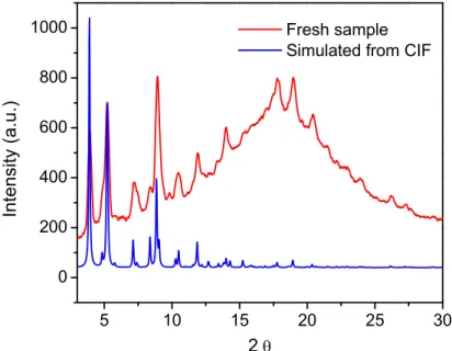
xylenes; iv) NaOH, THF, EtOH ...154 2-90. 5-3. A) Synthesis and characterization of CMOF - 11 and the formation
of the UiO-66 like structure containing octahedral and tetrahedral cages. B) TGA curve of CMOF – 11. Heating rate 3 °C/min to 600 °C.
C) PXRD pattern of fresh CMOF – 11 and simulated from the CIF file. D) TGA Curve of CMOF – 11 and CMOF – 11 after soaking in a 20 mg/mL methanol solution of Brilliant Blue R-250. Comparing from 300 – 600 °C after initial loss of solvent. E) NMR solvent analysis of CMOF – 11 using
mesitylene internal standard ...155
2-91. 5-4. PXRD pattern of CMOF-11 before and after metallation with
Ru(COD)(Me-allyl)2 ...158 2-92. 5-5. NMR Spectra of the hydrogenation of methyl-3-oxobutanoate
catalyzed by CMOF – 11 Ru ...170 2-93. 5-6. GC trace of the hydrogenation of methyl-3-oxobutanoate catalyzed
by CMOF – 11· Ru. γ-dex 225 Inj: 220 °C. Det: 250 °C. Column temp: 70 °C isothermal for 30 minutes followed by a ramp of 15 °C/min to 150
degree and held for 5 minutes. Column flow: 1.0 mL/min ...171 2-94. 5-7. NMR Spectra of hydrogenation of ethyl-3-oxopentanoate catalyzed by
CMOF – 11·Ru ...171 2-95. 5-8. GC trace of hydrogenation of ethyl-3-oxopentanoate catalyzed by
CMOF – 11·Ru. β – dex 225. Inj: 220 °C. Det: 250 °C. Column Temp: 60 °C
isothermal 30 min followed by ramp at 0.5 °C/min to 100 °C. Column Flow. 1
mL/min ...172 2-96. 5-9. NMR spectra of the hydrogenation of tert-butyl-3-oxobutanoate
catalyzed by CMOF – 11·Ru ...172 2-97. 5-10. GC trace of the hydrogenation of tert-butyl-3-oxobutanoate catalyzed by
CMOF – 11·Ru. γ – dex 225. Inj: 220 °C. Det: 250 °C. Column temp: 50 °C
isothermal for 160 minutes. Column Flow 1.24 mL/min ...173 2-98. 5-11. NMR Spectra of the hydrogenation of methyl-3-oxobutanoate catalyzed
by Ru(L8-Me2)Cl2(DMF) ...173 2-99. 5-12. GC trace of the hydrogenation of methyl-3-oxobutanoate catalyzed by
xxi
2-100. 5-13. NMR Spectra of hydrogenation of ethyl-3-oxopentanoate catalyzed by
Ru(L8-Me2)Cl2(DMF)2 ...174 2-101. 5-14. GC trace of the hydrogenation of ethyl-3-oxopentanoate catalyzed by
Ru(L8-Me2)Cl2(DMF)2. β – dex 225. Inj: 220 °C. Det: 250 °C. Column Temp:
60 °C isothermal 30 min followed by ramp at 0.5 °C/min to 100 °C. Column
Flow. 1 mL/min ...175 2-102. 5-15. NMR spectra of the hydrogenation of tert-butyl-3-oxobutanoate catalyzed
by Ru(L8-Me2)Cl2(DMF)2 ...175 2-103. 5-16. . GC trace of the hydrogenation of tert-butyl-3-oxobutanoate catalyzed
by Ru(L8-Me2)Cl2(DMF)2. γ – dex 225. Inj: 220 °C. Det: 250 °C. Column temp: 50 °C isothermal for 160 minutes. Column Flow 1.24 mL/min ...176 2-104. 5-17. GC trace of the hydrogenation of dimethyl itaconate catalyzed by
CMOF – 11·Ru ...176 2-105. 5-18. GC trace of the hydrogenation of methyl α-acetamidoacryalte catalyzed
by CMOF -11·Ru ...177 2-106. 5-19. HPLC trace of the hydrogenation of methyl α-acetamidocinnamate
catalyzed by CMOF – 11·Ru ...177 2-107. 5-20. GC trace of the hydrogenation of dimethyl itaconate catalyzed by
Ru(L8-Me2) Cl2(DMF)2 ...178 2-108. 5-21. GC trace of the hydrogenation of methyl α-acetamidoacrylate catalyzed
by Ru(L8-Me2)Cl2(DMF)2 ...178 2-109. 5-22. HPLC trace of the hydrogenation of α-acetamidocinnamate catalyzed by
Ru(L8-Me2)Cl2(DMF)2 ...179 2-110. 5-23. GC trace of the hydrogenation of dimethyl itaconate using
CMOF-11• Ru (1 h reaction time) ...180 2-111. 5-24. GC trace of the hydrogenation of dimethyl itaconate using the
supernatant of CMOF-11•Ru ...180 2-112. 5-25. GC trace of the hydrogenation of methyl α-acetamidoacryalte
catalyzed by CMOF-11•Rh ...181 2-113. 5-26. HPLC trace of the hydrogenation of methyl α-acetamidocinnamacryalte
catalyzed by CMOF -11•Rh ...182 2-114. 5-27. GC trace of the hydrogenation of methyl α-acetamidoacryalte
xxii
2-115. 5-28 HPLC trace of the hydrogenation of methyl α-acetamidocinnamacryalte catalyzed by Rh(L8-Me2)(COD)ClO4 ...183 2-116. 5-29. HPLC trace of the addition of phenylboronic acid to 2-cyclohexeneone
catalyzed by CMOF-11•Rh. Chiralcel AD. 99:1 Hexanes:isopropanol. 0.6
mL/min ...184 2-117. 5-30. 1H NMR spectrum of the addition of phenylboronic acid to
2-cyclohexeneone catalyzed by CMOF-11•Rh ...184 2-118. 5-31. HPLC trace of the addition of methyl-3-carboxyphenylboronic acid
to 2-cyclohexeneone catalyzed by CMOF-11•Rh. Chiralcel AD. 99:1
Hexanes:isopopanol. 0.6 mL/min ...185 2-119. 5-32. 1H NMR spectrum of the addition of methyl-3-carboxyphenylboronic
acid to 2-cyclohexeneone catalyzed by CMOF-11•Rh ...185 2-120. 5-33. HPLC trace of the addition 3-formylphenylboronic acid to
2-cyclohexeneone catalyzed by CMOF-11•Rh. Chiralcel AD. 92:8
Hexanes:isopropanol. 0.6 mL/min ...186 5-34. 1H NMR spectrum of the addition of 3-formylphenylboronic acid to
xxiii
LIST OF ABBREVIATIONS
MOF Metal-organic framework
SBU Secondary building unit
CMOF Chiral meal-organic
framework
DMF Dimethylformamide
DEF Diethylformamide
DBF Dibutylformamide
DMA Dimethylacetamide
TFA Trifluoroacetic acid
THF Tetrahydrofuran
Mes Mesitylene
DCM Dichloromethane
EDTA
ethylenediamine-tetraacetic acid
COD 1,4-Cyclooctadiene NBD Norobornadiene
EDA Ethyl diazoacetate
PXRD Powder X-ray diffraction
TGA
Thermogravi-metricanalysis
ICP-MS Inductively coupled
plasma mass spectrometry
ESI Electrospray ionization
NMR Nuclear magnetic
xxiv
UV-Vis Ultraviolet-visible
spectroscopy
NIR Near Infrared
GC Gas Chromatography
HPLC High performance liquid
chromatography
e.e Enantiometric excess
d/r diastereometric ratio
CIF Crystallographic
information file
MLCT Metal-to-ligand charge
transfer
LMCT Ligand-to-metal charge
CHAPTER 1
METAL-ORGANIC FRAMEWORKS FOR ASYMMETRIC CATALYSIS – AN INTRODUCTION
1.1 Why asymmetric catalysts, and why metal-organic frameworks?
The importance of chiral molecules in biological systems cannot be overstated. The various amino acids and sugars that form the building blocks of life are nearly exclusively L
-amino acids and D-sugars, respectively.1 This reality has important implications in medical
2
zeolites, however, would destroy any features of chirality and preclude them from being a viable option for a solid-state asymmetric catalyst.
Metal-organic frameworks (MOFs), also known as coordination polymers, are porous crystalline materials built from joining metal ions or ion clusters with organic bridging ligands.3 Like zeolites, metal-organic frameworks (MOFs) have been demonstrated in the last decade to be competent catalysts for asymmetric transformations. This ability, which is not available to zeolite materials, is due to the relatively mild conditions under which MOFs are synthesized. Solvothermal and diffusion crystallizations used for MOF synthesis are much milder methods than the calcination process to remove templates from zeolites, allowing for the incorporation of delicate chiral moieties into a MOF without racemization or decomposition of the chiral sites.
3
platform bridging heterogeneous and homogeneous asymmetric catalysis and combine the benefits of both: the system exhibits the facile recyclability of heterogeneous systems while still maintaining the reproducibility and single-site nature of homogeneous systems.
1.2 Sources of chirality
Asymmetric catalysis cannot be accomplished without a source of chirality. Before discussing how asymmetric catalysis is conducted with MOFs, it is best to understand the methods by which chiral MOFs can be synthesized. Of all the methods, three general schemes predominate: seeding, templating, and the use of enantiopure linking ligands (Table 1-1).4
Table 1-1. The various methods of introducing chirality into a metal-organic framework.
One route for synthesizing chiral MOFs is to grow them from achiral starting materials, which can be achieved if the framework material crystallizes in a chiral space group. A well-studied example of this chiral self-resolution phenomenon was discovered by Ezuhara et. al.5 In this example, [5-(9-anthracenyl)]pyrimidine was treated with cadmium nitrate tetrahydrate to grow enantiopure crystals. It was discovered that if crystals of a particular handedness of the material were used to seed the crystal growth, a bulk material with the corresponding handedness would result. However, relying on framework materials to crystallize into chiral space groups as a source of chirality has some drawbacks. Not all systems will undergo this chiral self-resolution, and even if single crystals of a given
Sources of Chirality
Growth from achiral starting
4
framework do grow into chiral space groups, the bulk material in the absence of any outside influence will be racemic, consisting of an equal distribution of both enantiomers.
While the possibility of achieving a homochiral MOF without the use of chiral ligands is enticing, it relies on the chance crystallization of the MOF into a chiral space group. A more reliable method involves the use of a chiral co-ligand to direct the handedness of the crystal growth. Rosseinsky demonstrated the use of 1,2-propanediol to direct the handedness of helices formed from nickel nitrate and benzenetricarboxylic acid.6 In this example, the chiral co-ligand, while present in the growth solutions, did not constitute any part of the desolvated structure. Other examples using this method of introducing chirality into a MOF include the zinc(L-lac) material reported by Dybtsev et al.; this material was
grown with L-lactic acid as the co-ligand, which in this case remained part of the structure
after crystal growth.7 As we will see later in this chapter, the use of chiral templates has also been used in the synthesis of catalytically active framework materials.
5
based on these ligand systems are well studied, and the scope of their reactivity is broad due to the wide range of metals that can be used with these ligands. These aspects make them ideal candidates for their immobilization in MOFs.
1.3 Benefits of MOFs in asymmetric catalysis
MOFs, like other heterogenized catalysts, can be easily removed by simple filtration methods and then recycled. The ease of catalyst removal from a reaction medium also helps reduce heavy metal contamination in the product. This advantage of heterogeneous catalysts over their homogeneous counterparts is of particular importance in the pharmaceutical industry, where trace heavy metal contamination is often not acceptable. The ease of recycling also allows for MOFs to utilize more expensive or synthetically challenging chiral ligands in their synthesis; because the catalyst is recoverable after the reaction, it becomes economically viable to utilize more efficient yet costly chiral ligands on large scales.
MOFs can also offer enhanced activity over other heterogenized or homogeneous systems. Because of the high degree of order that the active catalyst sites exhibit, it is possible to limit decomposition pathways within framework materials. This increased activity is exemplified in the manganese-salen framework reported by Lin et al.10 In this example, the bimolecular decomposition pathway that leads to catalyst deactivation is suppressed by restraining the motion of the catalytic moieties to the walls of the framework channels. Beyond enhancing the activity of the catalyst, the selectivity of MOF-based systems can be enhanced via confinement effects and restrained motion of the chiral ligand.9, 11 Several reports by the groups of Kim and Duan demonstrated increases in the selectivity of
6
Beyond the benefits in selectivity and stability afforded by MOF catalysts, the crystalline nature of these materials also allows for precise structure-function relationships to be elucidated. By utilizing single-crystal X-ray diffraction, the structure of the active catalytic sites in a MOF and the effect of the environment around the catalytic center can be determined. Lin et al. were able to use the structure of an isolated titanium BINOLate-functionalized framework to rationalize the decreased selectivities that were observed in the catalytic alkylation of aldehydes.12 In this case, an intermolecular cross-linking was responsible for the change in the active site, which, in turn, reduced the chiral induction imparted on the catalytic active site.
Figure 1-1. Inter- vs. intramolecular coordination of titanium as revealed by X-ray diffraction. The crystallinity of MOFs offers unique opportunities to elucidate structure-function relationships.
1.4 Early examples of symmetric catalysis with metal-organic frameworks
7
synthesized from a tartaric acid derivative and zinc nitrate hexahydrate (Figure 1-2).13 The resulting 2-dimensional structure contained trinuclear zinc cluster SBUs, which were connected by six ligands bound to the SBUs through their carboxylate moieties. Three of these ligands were coordinated to adjacent SBUs through their pyridine functionalities, resulting in a face-on hexagonal 2-dimensional framework.
Figure 1-2. The synthesis of a face-on hexagonal two-dimensional framework and the kinetic resolution of 1-phenyl-2-propanol as reported by Kim and coworkers.
The remaining three ligands do not participate in the network structure; instead, they have their pyridine groups dangling in the open channels. Kim et al. believed that these accessible basic sites could be utilized for catalysis and screened the material for activity in the asymmetric transesterification reaction of ethyl-2,4-dintrobenzoate with racemic 1-phenylproanol. They observed that the resulting transesterified product contained a slight enantiomeric excess (e.e.) of 8%.
8
Figure 1-3. A 2-dimensional, lamellar, chiral framework and its activity in the asymmetric ring opening of meso-epoxides.
This material was screened for activity in the cyanosilylation of aldehydes; nearly racemic products were obtained with all of the substrates that were screened. When the material was screened in the ring opening of meso cyclic anhydrides, small enantioselectivies were observed (5% e.e.). The disappointing selectivities exhibited by these two examples reveal the inefficiencies of utilizing remote induction of chirality onto a Lewis acidic SBU to produce an enantioselective catalyst.
9
enantioselectivities of up to 95% with quantitative conversion. This material represented the first time that a rationally designed coordination polymer catalyst was utilized for asymmetric reactions.
Extending this concept to a crystalline system, Lin and coworkers demonstrated the first highly enantioselective asymmetric reaction catalyzed by a crystalline metal-organic framework. In this work, the group developed a crystalline material from a 4,4’-dipyridine-substituted BINOL linker and cadmium nitrate.16 The 3-dimensional material consisted of Cd(µ-Cl)2 chains bridged by pairs of interlocking, hydrogen-bonded ligands, forming a 2-dimensional network. A third ligand then bridged these 2-2-dimensional networks into a 3-dimensional structure. While the hydroxyl groups of the tightly bound ligand pairs were inaccessible as catalytic sites due to steric crowding, the third bridging ligand possessed chelating sites that were accessible to the open channels (Figure 1-4).
Figure 1-4. The synthesis of a 3-dimensional chiral framework from a 4,4’-pyridyl substituted BINOL ligand .The framework consists of a 2-dimentional network consisting of zig-zag chains of Cd(µ-Cl)2 SBUs (red chains) connected by hydrogen-bonded ligand pairs (blue rods). The 2-dimensional layers are connected by a third ligand (yellow rods) to form the 3-dimensional framework.
10
determined. Using various substituted aromatic aldehydes, the reactions exhibited high yields and enantioselectivities, comparable to those of the homogeneous catalyst. It was also observed that the activity of the catalyst was inversely related to the size of the substrate.
Like carbonyl groups, alkenes offer a wide scope of reactivity from which new functionalities can be constructed. Using the alkene functionality as a synthetic handle, the oxidation of the double bond is an attractive method of developing chiral synthons. Using this inspiration, Hupp, Nguyen, and coworkers reported the first MOF-based catalyst for the asymmetric epoxidation of alkenes.17 In this system, a pyridine-derived salen catalyst was metalated with manganese and then subsequently oxidized to form the manganese(III)-salen chloride complex. Treating this ligand with zinc nitrate in the presence of 4,4’-bipyridine led to a layered structure composed of sheets of salen ligands connected by dinuclear zinc paddlewheel SBUs. These 2-dimensional layers were connected by the 4,4’-bipyridine co-ligands to form a 3-dimensional structure (Figure 1-5).
Figure 1-5. Epoxidation of 2,2,-dimethyl-2H-chromene using a pillared MOF framework reported by Hupp and coworkers.
-11
butylsulfonyl)iodosylbenzene. Recycling the MOF showed only a mild loss of activity without a decrease in selectivity. Leaching experiments showed that between 4 and 7% of the initial manganese leached out of the sample during the reaction either as the free molecular species or as particles too small to be trapped by filtration. Heterogeneity tests, however, showed that this small amount of leaching did not contribute to the overall production of epoxide product. While the MOF catalyst was unable to match the selectivity of the homogeneous catalyst, turnover numbers of >3000 were obtained for the MOF versus ~1000 for the free catalyst under identical conditions. The increase in the turnover number exemplifies the advantage of a highly ordered MOF catalyst; by restricting the motion of catalytic units via incorporation into the framework, intermolecular decomposition pathways are eliminated, thus increasing the lifetime of the catalyst.
12
Figure 1-6. Synthesis of a series of chiral MOFs with varying channel sizes controlled by framework catenation and ligand length.
1.5 Outlook and future directions
The work done to date has convincingly demonstrated the ability of MOFs to act as highly active and selective catalysts for a range of asymmetric chemical reactions. Furthermore, MOF catalysts can be more active than their homogeneous counterparts. A more complete account of the scope of metal-organic frameworks in asymmetric reactions has been reviewed elsewhere.18 The field of MOF catalysis is however still at its infancy. Most of the reactions studied to date take advantage of simple acid and base catalysis and thus are limited to fairly simple chemical transformations and are quite limited in scope. Many of the MOF catalysis studies merely represent another means of catalyst heterogenization.
13
development of size selective, sequential, and tandem catalytic systems. The low densities, high degrees of porosity, and extremely high volumetric surface areas suggest that MOFs may have potential applications in new flow reactor systems. The future of these materials lies in applications in which the high degree of order as well as unprecedented tunability can be exploited for practical purposes.
In order to achieve these goals, several avenues of research should be pursed. The structure-function relationships between metal-organic frameworks and the reactions that they catalyze must be better understood in order to engineer tailored materials for specific applications. Additionally, the mechanical and chemical stability of these materials must be improved in order to open up the application of MOF catalysts to a larger range of reaction conditions. Current MOF materials tend to be unstable at extreme pH’s or in the presence of strong chelating compounds. Coupled with these fundamental developments, synthesis of frameworks that contain more elegant transition metal-inspired catalytic moieties must be pursued.
14
REFERENCES
1. a) Noyori, R., Angew. Chem. Int. Ed. 2002,41, 2008; b) Knowles, W. S., Adv. Synth. Catal. 2003,345, 3; c) Farina, V.; Reeves, J. T.; Senanayake, C. H.; Song, J. J., Chem. Rev. 2006,106, 2734.
2. a) Zhou, Y. G.; Tang, W.; Wang, W. B.; Li, W.; Zhang, X., J. Am. Chem. Soc. 2002,124, 4952; b) Ireland, T. T., K.; Grossheimann, G.; Knochel, P., Chem. Eur. J. 2008, 14, 3509; c) Ireland, T.; Tappe, K.; Grossheimann, G.; Knochel, P., Chem. Eur. J. 2002,8, 843; d) Boaz, N. W.; Debenham, S. D.; Mackenzie, E. B.; Large, S. E., Org. Lett. 2002, 4, 2421; e) Thomas, J. M.; Maschmeyer, T.; Johnson, B. F. G.; Shephard, D. S., J. Mol. Catal. A: Chem. 1999, 141, 139-144; f) Sinou, D., Adv. Synth. Catal. 2002, 344, 221; g) Song, C. E.; Lee, S. G., Chem. Rev. 2002, 102, 3495; h) McMorn, P.; Hutchings, G. J., Chem. Soc. Rev. 2004,33, 108.
3. a) Robson, R.; Abrahams Brendan, F.; Batten Stuart, R.; Gable Robert, W.; Hoskins Bernard, F.; Liu, J., Crystal Engineering of Novel Materials Composed of Infinite Two- and Three-Dimensional Frameworks. In Supramolecular Architecture, American Chemical Society: 1992; Vol. 499, pp 256-273; b) Yaghi, O. M.; Li, H., Journal of the American Chemical Society 1995, 117 (41), 10401-10402; c) Robson, R., Journal of the Chemical Society, Dalton Transactions 2000,0 (21), 3735-3744; d) Yaghi, O. M.; O’Keeffe, M.; Ockwig, N. W.; Chae, H. K.; Eddaoudi, M.; Kim, J., Nature 2003,423, 705.
4. Lin, W., MRS Bull. 2007,32, 544.
5. Ezuhara, T., Endo, K., Aoyama, Y., J. Am. Chem. Soc. 1999,121, 3279-3283. 6. Kepert, C. J. P., T. J.; Rosseinsky, M. J., J. Am. Chem. Soc. 2000,122, 5158-5168.
7. Dybtsev, D. N.; Nuzhdin, A. L.; Chun, H.; Bryliakov, K. P.; Talsi, E. P.; Fedin, V.; Kim, K., angew. Chem. Int. Ed. 2006,45, 916.
8. a) Ranford, J. D.; Vittal, J. J.; Wu, D.; Yang, X., Angew. Chem. Int. Ed. 1999, 38, 3498; b) Abrahams, B. F.; Moylan, M.; Orchard, S. D.; Robson, R., angew. Chem. Int. Ed. 2003, 42, 1848; c) Sheldrick, W. S., Acta Crystallogr. 1981, B37, 1820; d) Aoki, K.; Saenger, W., J. Inorg. Biochem. 1983,19, 269.
9. Banerjee, M.; Das, S.; Yoon, M.; Choi, H. J.; Hyun, H. H.; Park, S. M.; Seo, G.; Kim, K., J. Am. Chem. Soc. 2009,131, 7524-7525.
10. Song, F.; Wang, C.; Falkowski, J. M.; Ma, L.; Lin, W., J. Am. Chem. Soc. 2010,132, 15390-15398.
15
12. Ma, L.; Wu, C.-D.; Wanderley, M. M.; Lin, W., Angew. Chem. Int. Ed. 2010, 49, 8244-8248.
13. Seo, J. S.; Whang, D.; Lee, H.; JUn, S. I.; Oh, J.; Jeon, Y. L.; Kim, K., Nature 2000,404, 982-986.
14. Evans, O. R.; Ngo, H. L.; Lin, W., J. Am. Chem. Soc. 2001, 123, 10395-10396.
15. a) Hu, A.; Ngo, H. L.; Lin, W., Angew. Chem. Int. Ed. 2003,42, 6000; b) Hu, A.; Ngo, H. L.; Lin, W., J. Am. Chem. Soc. 2003,125, 11490.
16. Wu, C.-D.; Hu, A.; Zhang, L.; Lin, W., J. Am. Chem. Soc. 2005, 127, 8940-8941.
17. Cho, S.-H.; Ma, B.; Nguyen, S. T.; Hupp, J. T.; Albrecht-Schmitt, T. E.,
Chem. Commun. 2006, 2563-2565.
CHAPTER 2
ISORETICULAR CHIRAL METAL-ORGANIC FRAMEWORKS AS A
TUNABLE PLATFORM FOR LEWIS ACID ASYMMETRIC CATALYSIS
2.1 Introduction
17
Figure 2-1. Schematic representation of a homochiral MOF and its postsynthetic modification (PSM) to a catalytically active MOF. (a) Cartoon showing the assembly of CMOFs and their postsynthetic modification to afford heterogenized asymmetric catalysts. (b) The chemical structures of the ligands used for this study. The L1a-L4a and L1b-L4b
notations are used to described both the protonated (as in free ligands) and deprotonated forms (as in CMOFs) of (R)-tetracarboxylic acids in this paper. R = Et for CMOF-1a to -4a and R = H for CMOF-1b to -4b. The primary carboxylic acid groups highlighted in red are used to form CMOFs whereas the secondary dihydroxy groups highlighted in blue will react with Ti(OiPr)4 upon postsynthetic modification to form asymmetric catalysts.
A series of tetracarboxylic acid ligands containing orthogonal chiral diethoxy (L1a to
L4a) or dihydroxy (L1b to L4b) functional groups in the (R)-enantiomeric form were
synthesized for this work (Figure 2-1). It was envisaged that metal connecting units could link these chiral bridging ligands together to form CMOFs via the carboxylate primary functional groups. The orthogonal chiral dihydroxy secondary functionalities in ligands L1b
18
to generate asymmetric catalytic sites that are accessible to the organic substrates via the open channels or cavities. In these proof-of-concept experiments, we chose carboxylate-bridged copper paddle-wheels as the targeted secondary building units (SBUs) to link the axially chiral bridging ligands to form CMOFs. This combination of building blocks has recently been used for constructing stable 4,4-connected MOFs of the PtS and related topology.26-30
2.2 Results and Discussion
2.2.1 Synthesis and characterization of isoreticular CMOFs
The enantiopure tetracarboxylic acid L1a was synthesized by cyanation of
4,4’,6,6’-tetrabromo-2,2’-diethoxy-1,1’-binaphthyl with CuCN in DMF at 130 C followed by base-catalyzed hydrolysis, whereas the enantiopure longer ligands L2a to L4a were synthesized by
Pd-catalyzed carbon-carbon coupling reactions between 4,4’,6,6’-tetrabromo-2,2’-diethoxy-1,1’-binaphthyl and methyl acrylate, 4-carboxyphenylboronic acid, and 4-carboxystryene, respectively, followed by base-catalyzed hydrolysis. Simultaneous deprotection of the methyl and chiral diethoxy groups of the methyl esters of L1a to L4a with excess boron tribromide
gave the ligands L1b to L4b in quantitative yields. All of these new ligands were characterized
by NMR spectroscopy and mass spectrometry.
19
characterization of the CMOF series). Repeated crystallization attempts with various Cu(II) salts and L1b failed to produce crystals suitable for single crystal X-ray diffraction, but
powder X-ray diffraction (PXRD) studies indicated that the polycrystalline product CMOF-1b obtained from the reaction carried out in the DEF/H2O solvent mixture is isostructural to CMOF-1a. The phase purity for each of the eight CMOFs was confirmed by an excellent match between the experimental and simulated PXRD patterns.
All of the eight CMOFs are isostructural and adopt a 3D non-interpenetrated framework structure of the same chiral space group, I4122.29 We will only describe the structure of CMOF-1a in detail here. The asymmetric unit of CMOF-1a contains one Cu atom, one half ligand L1a and one coordinated DEF for the framework. The Cu atom is
coordinated by four carboxylate oxygen atoms of four different L1a ligands in the equatorial
positions and one DEF molecule in the axial position to afford a square pyramidal geometry. The resulting copper paddle-wheel [Cu2(O2CR)4] SBUs are interconnected by the L1aligand
20
Figure 2-2. Crystal structure of CMOF-1a. (a) A view of [Cu2(O2CR)4] paddle-wheels and their connectivity with the L1a ligands in CMOF-1a. (b) Representation of the L1a
ligand as a blue distorted tetrahedron and the [Cu2(O2CR)4] paddle-wheel as a red square. (c) A simplified connectivity scheme of L1a ligands (blue distorted tetrahedra) and [Cu2(O2CR)4]
21
Figure 2-3. Space-filling models showing packing diagrams of CMOF-1b to -4b. The figures on the left (a, c, e, and g) show the packing diagrams of CMOF-1b to -4b as viewed down the a/b axis. The figures on the right (b, d, f, and h) show the packing diagrams of CMOF-1b to -4b as viewed down the c axis. The figures for CMOF-1b were generated by replacing the ethyl groups of CMOF-1a with hydrogen atoms.
22
diethoxy (CMOF-1a to -4a) and dihydroxy (CMOF-1b to -4b) functional groups (Table 2-1). Because of different lengths of the tetracarboxylate ligands, the CMOF series is highly porous with a tunable void space ranging from 73.3% to 91.9% as calculated by PLATON for the CMOF-1b to -4b series (Table 2-1).31 The ethoxy-protected CMOF-1a to -4a series has a void space ranging from 68.5% to 90.0%. As shown in Figure 2-3, the CMOF-1b to -4b series has tunable channel openings of 1.3 × 1.1 nm to 3.2 × 2.4 nm along the a/b axis and from 0.8 × 0.8 nm to 1.9 × 1.9 nm along the c axis. As expected, the CMOF-1a to -4a series has slightly smaller open channels due to the steric bulk of the ethyl groups. The calculated framework density for the CMOFs ranges from 0.730 to 0.177 g/cm3. With the chiral dihydroxy groups pointing toward the open channels, the CMOF-1b to -4b series provides an ideal platform for generating heterogeneous catalysts by grafting a secondary metal center via postsynthetic modifications.22, 32-34 As a result of their highly disordered nature, it is difficult to precisely determine and locate the included solvent molecules in the CMOFs by X-ray crystallography. We have used a combination of 1H NMR spectroscopy and thermogravimetric analysis (TGA) to establish the solvent contents in the CMOFs (see Table 2-1 for the details on the solvent contents). TGA analyses showed that the CMOF-1b to -4b series exhibits an impressive solvent weight loss of 58.4 wt% to 73.3 wt% in the 25 to 200
C temperature range (Table 2-2), confirming their highly open framework structures.
23
Table 2-1. Summary of key parameters and characterization data for CMOFs 1a-4a
CMOF- 1a 2a 3a 4a
Framework formula (L1a)Cu2(DEF)2 (L2a)Cu2(H2O)2 (L3a)Cu2(H2O)2 (L4a)Cu2(H2O)2
Framework density
(g/cm3) 0.730 0.375 0.290 0.187
Void space (%) 68.5 83.3 86.3 91.0
Channel sizes (nm2) 1.3 × 1.1 0.4 × 0.4
2.2 × 1.5
1.1 × 1.1
3.0 × 2.0
1.4 × 1.4
3.2 × 2.4
1.9 × 1.9
Solvent contenta 3.5DEF•4H
2O 15DMF•11H2O 12DEF•16H2O 10DEF•14DMA•5H2O
Solvent weight loss (%) by TGAb 40.3 62.8 62.0 69.1
Calc surface areac (m2/g) 2418 4101 4419 4514
Exp. surface areac (m2/g) 216 ~0 240 ~0
24
Table 2-2. Summary of key parameters and characterization data for CMOFs 1b-4b
CMOF- 1b 2b 3b 4b
Framework formula (L1b)Cu2(DEF)2 (L2b)Cu2(H2O)2 (L3b)Cu2(H2O)2 (L4b)Cu2(H2O)2
Framework density
(g/cm3) 0.696 0.356 0.284 0.177
Void space (%) 73.3 84.8 87.1 91.9
Channel sizes (nm2) 1.3×1.1 0.8×0.8 2.2×1.5 1.3×1.3 3.0×2.0 1.6×1.6 3.2×2.4 2.1×2.1
Solvent contenta 6.5DEF•9H
2O 11DEF•3H2O 13DMF•11iPrOH•4.5H2O
6.5 DEF•-
19 DMF•-
8.5 iPrOH•-
2 H2O
Solvent weight loss (%) by TGAb 58.4 63.5 66.0 73.3
Calc surface areac (m2/g) 2699 4186 4355 4219
Exp. surface areac (m2/g) 343 ~0 ~0 ~0
Dye uptake (wt%) 1.9 64.5 117 124
25
paddle-wheels and tetracarboxylate bridging ligands.26-30 Given the highly elongated structures of the tetracarboxylate ligands, it is surprising to observe the formation of non-interpenetrating structures in all of the CMOFs. We believe that the steric bulk of both the copper paddle-wheel SBUs and the 4,4’,6,6’-substituted BINOL-derived ligands prevents the CMOFs from adopting interpenetrated structures.39, 40 This work highlights the ability to engineer isoreticular CMOFs with tunable open channel sizes and functional groups by using chiral tetracarboxylate ligands of different lengths.
26
X-ray diffraction studies indicated that the elongated tetracarboxylate bridging ligands used in this work led to desired mesoporosity in CMOFs, a property that is required for asymmetric catalysis due to the need to transport very large reagent and product molecules. The large channels and pores cause severe framework distortion of these MOFs upon solvent removal, thus presenting a significant challenge in determining and quantifying their porosity. The gas adsorption experiments typically used to determine porosity gave meaninglessly small surface areas and pore sizes for the CMOFs; the gas adsorption measurements of the CMOF series gave less than 5% of the BET surface areas that were predicted based on GCMC simulations of the desolvated CMOFs.
27
28
29 2.2.2 Enantioselective catalysis
The results from GCMC calculations and dye uptake experiments strongly indicate that significant void space exists in the CMOF series and should be accessible to large organic molecules. The chiral dihydroxy groups in CMOF-1b to -4b are particularly attractive for further functionalization with a secondary metal center to afford active catalysts. Ti(IV) complexes of 1,1’-bi-2-naphthol (BINOL), for example, have been shown to catalyze a number of highly enantioselective reactions, such as addition of diethylzinc or alkynylzinc to aromatic aldehydes to afford a wide range of chiral secondary alcohols (upon hydrolytic workup).45 We believe that Ti(OiPr)4 can react with the chiral dihydroxy groups in
30
Figure 2-5 CMOF-derived asymmetric catalysts and their framework stability. a) Schematic representation of asymmetric alkyl- and alkynylzinc additions catalyzed by the CMOF/Ti-BINOLate catalyst inside large open channels. ICP-MS analyses indicate binding of Ti(IV) to the CMOF framework. b) PXRD patterns of CMOF-3b, Ti(OiPr)4-treated CMOF-3b, and recovered CMOF-3b/Ti(OiPr)4 catalysts after diethylzinc and alkynylzinc addition reactions. The identical PXRD patterns between these samples indicate that the framework structure of CMOF-3b is maintained after Ti(IV) loading and after catalytic diethylzinc and alkynylzinc addition reactions
31
32
Table 2-3. Diethylzinc additions to aromatic aldehydes catalyzed by the CMOF/Ti(OiPr)4 combinations
Entry CMOF- Ar Selectivity % Conv. % ee%
1 3b 1-Naph 92 >99 91
2 3b 4-Cl-Ph 84 >99 80
3 3b 4-Br-Ph 70 96 80
4 3b 4-Me-Ph 74 >99 78
5 3b Ph 68 >99 82
6 L3b-Me4 1-Naph 70 94 94
7 L3b-Me4 4-Cl-Ph >99 >99 88
8 L3b-Me4 4-Br-Ph 99 >99 87
9 L3b-Me4 4-Me-Ph >99 81 87
10 L3b-Me4 Ph >99 >99 86
11 4b Ph 82 >99 84
12 2b Ph 64 98 70
13 1b Ph 91 98 <3
14 3a Ph 10 >99 0
15 4b 1-Naph 70 60 91
16 2b 1-Naph 87 >99 86
17 1b 1-Naph 95 81 9
18 3b Ph 51 >99 66
19 3b Ph 93 >99 72
20 3b Ph 97 97 67
21 3b Ph 98 93 68
22 3b Ph 98 87 57
23 3b Ph 99 99 64
aAll the reactions were carried out with vigorous stirring with a magnetic stir bar except entries 18-23 in which the mixtures were only gently agitated to avoid pulverizing the solid catalysts in order to facilitate the recovery of CMOFs. This experimental deviation gave rise to different level of e.e.’s since diffusion of the substrates in entries 18-23 is slower so the contribution from the non-enantioselective background reaction is higher.
33
34
The dependence of e.e. values on the channel sizes was also observed to some extent when 1-naphthaldehyde was used as the substrate (entry 1, 15-17). The e.e. values increased in the order of 9%, 86%, 91%, and 91% for the CMOF-1b to -4b series. PXRD experiments suggested that the framework of CMOF-4b is the least stable and tends to distort easily. We believe that such a distortion of the CMOF-4b framework can reduce effective sizes of the open channels, and as a result, CMOF-4b gave only slightly higher e.e. than CMOF-3b in diethylzinc addition to benzaldehyde and the same e.e. as CMOF-3b in diethylzinc addition to 1-naphthaldehyde.
O
Ar + Et2Zn
*
OH
Ar
H Ti(OiPr)4
homochiral MOFs
+ Zn(Et)(CCPh)
Ti(OiPr)4
homochiral MOFs
*
OH Ar Ph O Ar H (Eq. 1) (Eq. 2)Ph 4-Me-Ph 4-Cl-Ph 4-Br-Ph 1-Naph
CH3 Cl Br
Ar =
Figure 2-6. Scheme showing asymmetric diethylzinc and alkynylzinc additions catalyzed by the CMOF/Ti(OiPr)4 catalyst. Eq. 1 shows diethylzinc additions and Eq. 2 shows alkynylzinc additions. The chemical structures of the aldehyde substrates and secondary alcohol products are also shown.
35
alcohols with complete conversions and up to 76% e.e. The solid catalyst recovered from the alkynylzinc addition reaction exhibited the same PXRD as the pristine solid of CMOF-3b (Figure 2-5), demonstrating that the CMOF framework is stable under the catalytic alkynylzinc addition reaction conditions. Control experiments with CMOF-3a also indicated a significant background reaction catalyzed by the non-chiral active sites to give the racemic alcohols. The lower e.e. values observed for the CMOF-3b/Ti(OiPr)4 catalyst as compared to the homogeneous catalyst is probably due to the competing non-enantioselective background reaction.46 It is interesting to note that the reaction with 1-naphthaldehyde gave a much lower e.e. than the other aromatic aldehydes, presumably due to the hindered diffusion of the large aldehyde and alkynylzinc reagents.
Table 2-4. Alkynylzinc additions to aromatic aldehydes catalyzed by the CMOF/Ti(OiPr)4 combinations
entry CMOF- Ar Conv.% e.e.%
1 3b 4-Me-Ph >99 71
2 3b 4-Cl-Ph >99 59
3 3b 4-Br-Ph >99 69
4 3b 1-Naph >99 31
5 3b Ph >99 76
6 1b Ph >99 0
7 2b Ph >99 0
8 4b Ph >99 77
9 4b 1-Naph >99 49
10 3a Ph >99 0
36
channels due to the larger sizes of the reagents. Consistent with this, the CMOF-4b/Ti(OiPr)4 catalyst gave slightly enhanced enantioselectivity (77% e.e. for benzaldehyde and 49% e.e. for 1-naphthaldehyde) than the CMOF-3b/Ti(OiPr)4 catalyst (76% e.e. for benzaldehyde and 31% e.e. for 1-naphthaldehyde). These results demonstrated that the catalytic performances of the CMOF-derived catalysts are dependent on the sizes of the open channels due to the need to transport large reagent and product molecules.
2.3 Conclusions
37 2.4 Experimental
2.4.1 General Procedures and Instrumentation
All of the solvents were purchased from Fisher and used without further purification. All of the reactions and manipulations were carried out under Argon with the use of standard inert atmosphere and Schlenk techniques or inside a nitrogen-filled glovebox. 1NMR spectra were recorded on a Bruker NMR 400 DRX spectrometer at 400 MHz and referenced to the proton resonance resulting from incomplete deuteration of the deuterated chloroform (δ